A Structured Validation and Verification Method for Automotive ...
Recommend Documents
Sep 8, 2009 ... a specific intended use are fulfilled (ISO/IEC. 17025:2005 cl. 5.4.5.1) ...
requirements (ISO/IEC Guide 99:2007) ... (ISO/IEC 17025:2005 cl 5.4.3).
Nov 20, 2009 ... Validation of methods (cl. ... In particular, method validation and sample ... AOAC.
• smallest amount of analyte in a test sample that can be.
Whether it is an ISO-9001 [1], ISO-17025 [2], ISO-15189. [3] or similar quality management system, each comes with its own flavor of requirements regarding ...
Apr 26, 2013 - Association for Educational Communications and Technology 2013 ... solving often requires teams of experts and specialists interacting over.
Apr 26, 2013 - issues present obstacles to assessing complex and ill-structured ..... of water supplies and purification, settlement planning and building of ...
The resampling methods - bootstrap, jackknife and cross validation - are compared to the popular neural network validation methods of train-and-test and.
Development and Validation of a Method for Simultaneous Quantification of Seven Water-Soluble Vitamins in Pediatrics Syrup by UPLC-MS/MS. Harmita a.
Sep 2, 2012 - northeastern states of Pernambuco and Alagoas [14], and subsequently ...... Mota RA, Brito MF, Castro FJ, Massa M: Mormo em eqüídeos nos estados de Pernambuco e ... Brasília: Diário. Oficial; 2004:7–10. Seção 1. 18.
Apr 3, 2014 - NASA Ames Research Center, Moffett Field, CA, 94035 and. Matthew Daigle3 .... due to the force exerted by the return spring. From looking at .... the capabilities of. JPL-developed risk management software, DDP14 to record.
lation and update process and the quality control (validation) activities ..... clusions were that a limited number of facilities showed high uncertainties, e.g. ... more independent verification of the emission level and emission trends, e.g..
control software at the Dryden Flight Research Center. .... Certification Challenges for Adaptive and Autonomous Control Software ..... higher than expected wear environments, VHM algorithms identify failure trends and call for component.
challenges that must be addressed during the development of adaptive system software for use in safety-critical aerospace applications. The paper first ...
computer model with sufficient accuracy (Davis, 1992); in other words, building the ..... simulation software vendors offer a help desk service with which specific ...
model of the PC-LAN we carried out a walk-through of the simplified model ... It is important to remember that validation does not imply verification, nor verifica-.
(model verification) and whether the assumptions which have been made are reasonable ... The walk-through allowed us to detect that we needed to distinguish states .... the model should ideally be led by someone other than the modeller, ...
... State University. Department of Nuclear Engineering. Reactor Dynamics and Fuel Modeling Group. CTF Validation and Verification. November 26, 2016 ...
There are two steps to judging how good a model is with respect to the system. We must ... modelling, and modelling-specific techniques are discussed below.
the popular neural network validation methods of train-and-test and resubstitution. While the techniques covered in this chapter are especially aimed.
and propagate uncertainty because it is a mature mathematical theory applicable to the ..... Reciprocity check between excitation/measurement points 1 and 12.
BMW Manufacturing Co.,. Greer, South Carolina .... Andreas Obieglo is a PhD at BMW, Automotive Engineering. ..... Table 2, is used to assist in this process.
Benjamin W. Caldwell, Essam Z. Namouz, ... Reference to this paper should be made as follows: Caldwell, B.W., .... Services staff of Senator John D. Ashcroft.
Oct 5, 2017 - E-mail: [email protected] ..... symbol â of arity 2 and the constant 0 are used to model the exclusive or operator. .... that neq(u, v) â yes if, and only if, u and v can be reduced to messages that are not equal modulo E. .
A Structured Validation and Verification Method for Automotive ...
2011 [1], the automotive sector benefited from a consistent functional safety process for developing ... as well as details of software and hardware development.
A Structured Validation and Verification Method for Automotive Systems considering the OEM/Supplier Interface Kristian Beckers2 , Isabelle Cˆot´e2 , Thomas Frese3 , Denis Hatebur1,2 , and Maritta Heisel1 1
paluno - The Ruhr Institute for Software Technology – University Duisburg-Essen, email: {denis.hatebur,maritta.heisel}@uni-due.de 2 Institut f¨ur technische Systeme GmbH, Germany, email: {k.beckers,i.cote,d.hatebur}@itesys.de 3 Ford Werke GmbH, email: [email protected]
Abstract. The released ISO 26262 standard for automotive systems requires several validation and verification activities. These validation and verification activities have to be planned and performed jointly by the OEMs and the suppliers. In this paper, we present a systematic, structured and model-based method to plan the required validation and verification activities and collect the results. Planning and the documentation of performed activities are represented by a UML notation extended with stereotypes. The UML model supports the creation of the artifacts required by ISO 26262, enables document generation and a rigorous check of several constraints expressed in OCL. We illustrate our method using the example of an electronic steering column lock system. Keywords: Safety Management, Verification, Validation, ISO 26262, Automotive, UML, OCL, UML4PF, V&V
1
Introduction
Developing and constructing road vehicles has become a complex task due to the increase of features, such as adaptive cruise control or lane keeping assist functions. The safety aspects of these features have to be taken into account during the product development. Another fact is that most of these complex systems are distributed. Distributing the system amongst the different parties involved means that the overall system is broken down into several components and/or subsystems provided by different suppliers. This raises the complexity for the manufacturer (OEM), who has to organize the necessary V&V activities. With the release of ISO 26262 - Road vehicles – Functional safety in November 2011 [1], the automotive sector benefited from a consistent functional safety process for developing and constructing electric/electronic (E/E) systems. ISO 26262 addresses all levels of development, including definition of functions/features, systems engineering as well as details of software and hardware development. The standard should be applicable to different scenarios for establishing this process, including e.g., the OEM and any number of suppliers for the distributed systems.
Usually, the OEM division responsible for the development of the system creates the logical architecture and then distributes requirements to different divisions within the OEM responsible for the components. These divisions receive all requirements from systems in which their component is involved in, integrate the requirements and cascade the requirements to the component suppliers. They do the implementation and supply pieces of hardware and software that then have to be integrated into the vehicle. This distribution includes several challenges: For the requirement engineering, it has to be determined who has to provide which content at which level of detail. Some of the requirements engineering (RE) has to be done by the OEM and the supplementary RE has to be added by the suppliers. For the verification and validation (V&V), the OEM division responsible for the overall system has to ensure that the V&V tasks are defined and cascaded to the other divisions and the suppliers. Some aspects can only be validated on vehicle level by the OEM division responsible for the system (e.g. the overall behavior of the system), some aspects can be validated on component level by the divisions responsible for the components (e.g. the behavior of the component) and other aspects can only be validated using internal interfaces of the component by the suppliers. When the V&V is performed, the results of the V&V activities at suppliers side and within the different OEM divisions needs to be fed back and collected in an appropriate way to support the creation of the safety case. In addition, heterogeneous and concurrent engineering processes, methods and tools exists within the affected parties which need to be harmonized. Communication between OEM and divisions/suppliers has to be organized via requirements as well as verification and validation documents. Note that verification and validation are not always clearly distinguished in ISO 26262. Examples are part 3 section 8.4.5 “Verification of the functional safety concept” where a note mentions, that the same methods can be applied for verification and validation or part 4, section 6 “Specification of the technical safety requirements”, where verification and validation are addressed in the same sub-section. Another example, found in part 3 section 7.4.5, defines the verification of the hazard analysis, which is – according to the definition of the terms in part 1 – more a validation activity. Therefore, we do not distinguish between verification and validation actions and always talk about V&V and use the more general term “verification” throughout our paper. In this paper, we propose a structured method based on UML models supported by a tool for the V&V activities. This work is part of a larger model-based safety requirements engineering approach in support of ISO 2626 as described in Sect. 3. The papers referenced there also include V&V in the early development steps, i.e., the V&V of functional safety requirements regarding the safety goals and technical safety requirements regarding the functional safety requirements. This paper addresses the V&V activities in later development steps after handing-over requirements to the divisions and supplier(s). The advantage of a UML model-based approach is that the different artifacts are explicitly connected instead of having loosely coupled documents. On this overall model, consistency checks can be performed. These consistency checks can be specified with the Object Constraint Language (OCL) from the Object Management Group (OMG) [2]. Our paper is organized as follows: Background to our work is presented in Sect. 2, which is the ISO 26262 standard. We give an overview on our functional safety framework in Sect. 3. Section 4 outlines the tool support. Our case study is introduced in Sect. 5. Our method including the application on the case study is presented in Sect. 6. 2
This section also describes our UML profile, which can be used to express all relevant ISO 26262 artifacts. Section 7 presents related work, while Sect. 8 concludes the paper and gives directions for future work.
2
ISO 26262
ISO 26262 is a risk-based functional safety standard intended to be applied to safetyrelated systems that include one or more E/E systems and that are installed in series productions of passenger cars with a max gross weight of up to 3500 kg. It addresses possible hazards caused by malfunctions of E/E safety-related systems, including the interaction of these systems. ISO 26262 was derived from the generic functional safety standard IEC 61508 [3] and is aligned with the automotive safety life-cycle including specification, design, implementation, integration, verification, validation, configuration, production, operation, service, decommissioning, and management. ISO 26262 provides an automotive-specific risk-based approach for determining risk classes that describe the necessary risk reduction for achieving an acceptable residual risk, called automotive safety integrity level (ASIL). The possible ASILs are QM, ASIL A, ASIL B, ASIL C, and ASIL D. The ASIL requiring the highest risk reduction is called ASIL D. For functions with ASIL A, ASIL B, or ASIL C, fewer V&V requirements are given in ISO 26262. In case of a QM rating, the normal quality measures applied in the automotive industry are sufficient. Regarding the OEM-supplier interface, ISO 26262 Part 8 requires an appropriate definition (e.g. by using a development interface agreement), but as the application of the standard should be possible in different project scenarios, the standard does not predefine a dedicated split of technical responsibilities.
3
Functional Safety Framework
The Ford Integrated process for Functional Safety (FIFS) consists of templates, examples and guidelines in Microsoft Word and Microsoft Excel. These templates, examples and guidelines were developed and improved (using project feedback) since 2009. They were applied in more than 20 projects and cover all parts of ISO 26262 being relevant for an OEM who does not develop software and hardware. If the templates are applied according to the guidelines, ISO 26262 compliant (work) products are developed. The method is based on practical experience in the automotive domain. Within the V-model applied in ISO 26262, the first step of requirements engineering is to perform a hazard analysis and risk assessment for the system under consideration. Output of this step is given by the safety goals, describing the highest level of safety requirements. In the functional safety concept (FSC), the safety goals from the hazard analysis are broken down into functional safety requirements. These functional safety requirements are mapped to subsystems or components. The task of the subsequent step is to split the functional safety requirements up into technical safety requirements. Within our approach, the technical safety requirement categories SafetyRelatedFunction, UserInformation, MaintainSafeState Recovery, ExternalFaultHandling, LatentFaultHandling, Decomposition, and Metric are used. With these functional safety requirements and technical safety requirements, the requirement activities of the OEM are finalized within the setup chosen for our method. 3
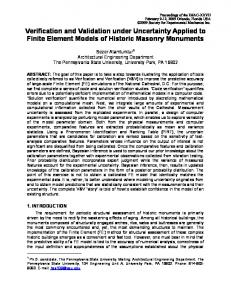
Fig. 1. Profile Part concerning Requirements and Components
The technical safety requirements are cascaded to the other OEM divisions and finally to the suppliers as described in Sect. 1. and the V&V phase is started. The method presented in this paper supports the planning and performing of V&V activities as well as the documentation of their results (see Sect. 6). It is embedded in the overall functional safety process according to ISO 26262. The created documentation is an essential part for the subsequent steps that result in the safety case. The safety case is the argument that the safety requirements for an item are complete and satisfied by evidence compiled from documents of all ISO 26262 safety activities during the whole lifecycle. It represents the key argument for the Functional Safety Assessment and product release and concludes the ISO 26262 development process. Aiming at tool support, we started to develop a UML profile and a set of OCL constraints to support the development activities. The whole approach was presented on the automotive industry conferences VDA Automotive SYS Conference 4 , Baden-Baden Spezial 2012 5 and Safetronic 2014 6 . The Electronic Steering Column Lock case study is used in all papers and presentations. In these papers, we introduced (among others) the following stereotypes (see Fig. 1): – To represent the system to be built the stereotype Item is introduced, – Relevant entities in the environment of the item are called domains ( domain ), – Requirements ( Requirement ) extending UML classes with the an attribute for the requirement text, – safety requirements ( SafetyRequirement ) being special requirements with attributes for the ASIL and the safe state, – safety goals ( SafetyGoal ) as a top-level requirement being a special safety requirement, – functional safety requirements ( FunctionalSafetyRequirement ), also being special safety requirements, systematically derived from the safety goals, – technical safety requirements ( TechnicalSafetyRequirement ), also being special safety requirements, systematically derived from the functional safety requirements and being the input for the supplier, – components or subsystems ( CompSubsystem ) extending UML classes, and – to show the relation between technical safety requirements and components or subsystems, the refersTo -dependency was created. 4
Table 1. Derived Technical Safety Requirements ID ESCL-T-SReq01000
ESCL-T-SReq01010
ESCL-T-SReq01040
4
Requirement SSM (Speed Sensor Module) shall measure vehicle speed and shall send vehicle speed signal with quality factor every 20 ms protected with checksum SSM shall detect faults (including sensor faults) leading to an erroneous vehicle speed information < PERMITTTED LOCKING SPEED with a tolerance of 2 km/h SSM shall fulfill the specified target value for PMHF
Purpose Category Vehicle speed signal is used to determine that the Safety Revehicle is at standstill, which is one of the condi- lated Function tions that allow steering column locking. For Safety Goal 01, valid vehicle speed is one infor- Internal Fault mation to detect if ESCL locking is allowed. There- Handling fore faults of vehicle speed shall be detected. Metric Requirement for Safety Related Function
Metric
Tool Support
We use a tool called UML4PF, developed at the University of Duisburg-Essen, and integrated support for the method to create a safety requirements specification as described in Sect. 6 into it. UML4PF is based on the Eclipse platform [4] together with its plug-ins EMF [5] and OCL [2]. Our UML-profile is conceived as an Eclipse plug-in, extending the EMF meta-model. The OCL constraints are integrated directly into the profile. Thus, it is possible to automatically check the constraints using the validation mechanisms provided by Eclipse. After the developer has drawn some diagram(s) using an EMF-based editor, for example Papyrus UML [6] and applied our stereotypes, UML4PF provides him or her with the following functionality: it checks if the developed model is valid and consistent by using our OCL constraints described in Table 5. It returns the location of invalid parts of the model, and generates documentation that can be used for the manual validation and review activities.
5
Case Study
Our case study is an electronic steering column lock (ESCL) system, which was introduced as case study in several presentations and papers (see Section 3). The item definition, the hazard analysis and risk assessment, the safety goals, the functional safety requirements, and the technical safety requirements exist as input. In this paper, we choose the safety goal SG01 “Locking the steering column when vehicle is moving shall be prevented” as an example from which the following functional safety requirement is derived: ESCL-F-S-Req 01: “The steering column shall only be locked if the physical vehicle speed information is valid (correct and in time) and the absolute value is lower than permitted locking speed. Invalid vehicle speed information shall be detected.” From this functional safety requirement, the technical safety requirements of different categories given in Table 1 were derived representing the implementation of the respective functional safety requirement in the speed sensing module (SSM).
6
V&V Method and Case Study
We propose a method for planning and documenting performed V&V activities. The V&V methods need to address the following ISO 26262 topics: For all technical and functional safety requirements, a link to an analysis (e.g. FMEA or fault tree analysis (FTA)) is required. For each functional and technical safety requirement, the correctness 5
external input method
Technical Safety Requirements
Functional Safety Requirements Safety Analyses
UML4PF ISO26262 Profile*
1. Link Requirements and Safety Analyses +
2. Plan Verificiation and Validation Activities
+
input/output
=
- Refined V&V Activities
* Needed in all subsequent Steps
=
=
- Detailled Plan for V&V Activities - Validated V&V Activities
OEM
5. Review Feedback for Technical Safety Requirements Verification +
4. Provide Task Feedback for Technical Safety Requirements +
3. Plan Responsibilities and Due Dates
=
- Links from Requirements to Safety Analyses
Supplier Engineering Documentation
Predefined V&V Activities
- Low Level Requirements - Refined Analysis and Verification Activities
+
=
- Review Feedback
6. Provide Task Feedback for Functional Safety Requirements and Safety Goal +
=
- Feedback for functional safety requirements and safety goals
7. Review Feedback for Functional Safety Requirements Verification
- Verification Review Results
8. Perform Confirmation Review
- Confirmation Review Results
Supplier
Fig. 2. V&V Method considering the OEM/Supplier Interface
and the completeness of the detailed V&V method (e.g. a test case in a test specification) needs to be assessed and it needs to be checked that the results of the V&V fulfill the acceptance criteria. From OEM perspective, it has to be ensured that the suppliers have derived and implemented appropriate hardware (HW) and software (SW) requirements for each technical safety requirement. This includes the application of the processes and methods as required by ISO 26262. Checking these processes and methods is an additional V&V step for the OEM. Additionally, the calculation of the HW metrics on safety goal level is required by ISO 26262, based on the input values provided by the suppliers. Details on metric calculation and corresponding V&V are provided in [7]. Within our method, we structure the V&V activities as follows: An engineering activity (e.g. derivation of HW and SW requirements by the supplier(s), or engineering V&V activities like analyses or testing). An engineering activity feedback (e.g. a reference to the derivation of HW and SW requirements, analyses or test cases). A safety V&V activity to check if the task feedback is appropriate (e.g. review if the derivation of the HW and SW is sufficiently justified, review if the applied analyses are according to ISO 26262, review if all safety aspects of a requirement are covered by test cases). A safety V&V activity feedback to document the results of the V&V activity. Our method includes matching the ISO 26262 topics to the different V&V activities. Figure 2 depicts an overview of our method consisting of eight steps in which we highlight for each activity the contribution of the OEM and its supplier(s). Each step is described in the subsequent paragraphs. We illustrate the application of these steps with functional safety requirements and some of the the exemplary technical safety requirements introduced in Section 5. Step 1. Link Requirements and Safety Analyses As input for this step, we need the functional and technical safety requirements, and the safety analyses, as well as our UML-profile. As the OEM is responsible for the overall system, he provides the majority of information for this step and requests specific information from involved suppliers. The suppliers are reacting upon demand of the OEM. ISO 26262 [1, Part 4: 7.4.3.1] requires that the safety analyses are consistent to functional as well as technical safety requirements. To ensure this, a mapping is created in this step: Each functional and technical safety requirement is linked to some part of the safety analyses, i.e., a line item of a Failure Mode and Effect Analysis (FMEA) [8] or a gate or event of a Fault Tree Analysis (FTA) [9]. The output is generated from the input by systematically comparing the elements contained in the analyses with the functional and technical safety requirements. 6
Fig. 3. Safety Analysis Linked to Requirements
Whenever an element in the analyses is found that is also addressed by a requirement, we establish a link between the element and the requirement. The UML4PF ISO 26262 profile provides appropriate stereotypes to support this step. We introduce the stereotype addressedBy , which extends the UML dependency. This dependency points from the analysis element to the corresponding requirement. Additionally, the FTA or FMEA elements need to be imported to the model. They can be represented by UML classes with the stereotype FTAGate , FTAEvent , or FMEALineItem . UML4PF offers us the opportunity to run some automated checks, e.g. it is possible to check that all technical and functional safety requirements address an element of an analysis (see condition 1C01RA in Table 5 7 ), and vice-versa (see condition 1C02AR in Table 5), and the stereotype addressedBy points from an analysis element (class with the stereotype FTAGate , FTAEvent , or FMEALineItem ) to a functional or technical safety requirement (see condition 1M03AR in Table 5). In the case study, the analysis used for the SSM is the fault tree analysis created during the system design phase. The analysis is systematically reviewed to identify the elements representing the functional and technical requirements: For example, the technical safety requirement ESCL-T-SReq01000 is represented by a gate block in the FTA (SSM L VSPD FA), describing that the SSC transmits a vehicle speed less than the permitted speed threshold even the real speed is higher or equal to the threshold. This is represented by using the UML class for FTAGates and the stereotype addressedBy in the class diagram. With the tool support, it is checked that all functional safety requirements and technical safety requirements are connected to an analysis element with the stereotype addressedBy . The result of this step is depicted in Fig. 3. Step 2. Plan V&V Activities As input for this step, we use the safety goals, the functional safety requirements, and the technical safety requirements with their categories and the components that realize these requirements. For each safety requirement certain V&V activities are necessary to fulfill different ISO 26262 requirements. An essential part of our method is a set of pre-defined V&V-activities (see Table 2). Taking project experience into account, we have defined these activities in a way that the ISO 26262 requirements ([1, Part 4, 6.4.2.2] for InternalFaultHandlingVaV , [1, Part 4, 6.4.2.2] for LatentFaultHandlingVaV , [1, Part 4, 7.4.3.4/5] for PMHFVaV , [1, Part 6, 9.4] for HW SWDerivationVaV , [1, Part 6, 10.4] for HW SWVerificationVaV , [1, Part 4, 8.4.3/4] for SRSVerificationSpecVaV , and [1, Part 4, 8.4.3/4] for SRSVerificationResultVaV ) can be fulfilled. For example for technical safety requirements of category “SafetyRelatedFunction”, we propose the following V&V activities: – HW SWDerivationVaV : The engineering activity is the derivation of detailed HW and SW requirements for each technical safety requirement. The engineering 7
The first number refers to the step in the procedure, C is for consistency checks, M is for checks considering correct modeling, G is for generation expressions; the next number is the number of the check within the step, and the last characters are an abbreviation of the description.
7
Table 2. V&V activities depending on the verified safety requirement type/category Requirement Category and ASIL SafetyGoal with ASIL C-D FunctionalSafetyRequirement (or derived) with QM FunctionalSafetyRequirement (or derived) with ASIL A-D TechnicalSafetyRequirement (or derived) with QM SafetyRelatedFunction or Decomposition or EmergencyOperationRequirement or UserInformation or MaintainSafeStateRecovery with ASIL A-D InternalFaultHandling with ASIL A-D
ExternalFaultHandling with ASIL A-D LatentFaultHandling with ASIL A-D
Metric with ASIL C-D SafetyRelatedFunction with ASIL A-D
V&V activities SG HW Metric has to be handled according to normal automotive processes FSCVerificationSpecVaV , FSCVerifiactionResultVaV has to be handled according to normal automotive processes HW SWDerivationVaV , HW SWVerificationVaV , VerificationSpecificationVaV , SRSVerificationResultVaV InternalFaultHandlingVaV , HW SWDerivationVaV , VerificationSpecificationVaV , HW SWVerificationVaV , SRSVerificationResultVaV HW SWDerivationVaV , HW SWVerificationVaV , VerificationSpecVaV , SRSVerificationResultVaV LatentFaultHandlingVaV , HW SWDerivationVaV , SRSVerificationSpecVaV , HW SWVerificationVaV , SRSVerificationResultVaV PMHFVaV , SRSVerificationSpecVaV HW SWDerivationVaV , HW SWVerificationVaV , SRSVerificationSpecVaV , SRSVerificationResultVaV
activity feedback is a reference to HW and SW requirements and the corresponding safety analysis, the safety V&V activity is the review of this feedback. – HW SWVerificationVaV : The engineering activity is the verification of the implemented HW and SW requirements. The engineering activity feedback is the reference to the component level verification measures, consisting of e.g. component test specifications and analyses and as safety V&V activity the review of this feedback. – VerificationSpecificationVaV : The engineering activity is the creation of a test case for the technical safety requirement. The engineering activity feedback is a reference to the test case, e.g. as part of a test specification, and the safety V&V activity is the review of this feedback. – SRSVerificationResultVaV : The engineering activity is the execution and documentation of the verification. The engineering activity feedback is the reference to the test report containing the results of the test case as feedback and the safety V&V activity is the review of this feedback. This step is usually performed by the OEM. The purpose of this step is to ensure that all safety related aspects of each safety requirement are covered by V&V activities. The input is used to plan which V&V activities have to be performed. The V&V activities are specific depending on the verified requirement. In Table 2, we show which activities are necessary for the different requirement categories. Tables 3 and 4 show all predefined details for the activities to be performed, as well as review criteria. In this step, we create classes with the stereotypes from the second column given in Table 2. Additionally, we create dependencies with the stereotype verifies from the classes with a stereotype derived from VaV to the corresponding requirement. The tool can generate the aforementioned classes and dependencies (see 2G01DR in Table 5). It can be checked that the stereotype VaVActivity is not used directly. Instead only its specialized stereotypes (see condition 2M02NV in Table 5) have been applied. For example, the technical safety requirement of category SafetyRelatedFunction gets the V&V activities as described in Section 6. Figure 5 shows the results for one example requirement of the case study. Step 3. Plan Responsibilities and Due Dates As input for this step, we use the output of Step 2. We can distinguish between different V&V activities. V&V activities 8
Fig. 4. Profile Part concerning V&V activities
Fig. 5. Planned V&V Activities for T-S-Req01000 of the ESCL Example
referring to functional safety requirements can usually be performed by the OEM. For V&V activities referring to technical safety requirements, OEM and supplier(s) have to plan which activity is performed by the supplier and which activity is performed by the OEM. If the OEM does not develop hardware and software, the related activities are usually performed by the supplier(s). Project experience shows that the verification of the suppliers’ activities is often done by the OEM. To reach the overall project milestones, it is necessary to assign responsible persons and define due dates for the activities. For the relevant activities, the responsible person to provide the feedback and the responsible person to verify this feedback shall be assigned. Additionally, a time to complete the task shall be defined. The V&V activities are specific depending on the verified requirement. In this step, we set the properties taskResponsible, taskDueDate, verificationResponsible, and verificationDueDate for the different V&V activities being a sub-type of VaVActivity (see center of Fig. 4). This enables us to check whether the attributes taskResponsible, taskDueDate, verificationResponsible, and verificationDueDate are set and not empty (see condition 3M01AS in Table 5). The specification of the test case for the technical safety requirement ESCL-T-S-Req01000 is done by the engineers responsible for the SSM component development at the suppliers side. The review of the test case is done by the OEM, the responsible person is the safety consultant of the ESCL development project. For VerificationSpecVaV , the properties taskResponsible and verificationResponsible are set and the necessary information (name, company, contact data) is provided accordingly. In addition, the properties taskDueDate and verificationDueDate are set and the due dates for the creation of the test case and the review of the test case are defined (see Fig. 7). The same procedure is applied to all V&V tasks. Step 4. Provide Engineering Activity Feedback for Technical Safety Requirements Input for this step is the documentation of engineering activities from OEM and supplier(s), including the derivation of lower level requirements, their analyses, and their verification activities and the output of all previous steps. For this step, the supplier(s) 9
Fig. 6. V&V Confirmation Review of ESCL Example
Fig. 7. V&V Activities for SRS of ESCL Example, Steps 3 and 4
provide necessary information to complete the requirements and V&V activities on HW and SW level. The OEM divisions or supplier(s) provide test specification, test results and safety analyses. Purpose of this step is to collect information according to the engineering activities as specified in Table 3. The output of this step is the feedback on the engineering activities (see Table 3) for all technical safety requirements. In this step, we set the attribute engineeringFeedback in the classes with the stereotypes InternalFaultHandlingVaV , LatentFaultHandlingVaV , HW SWDerivation VaV , PMHFVaV , HW SW VerificationVaV , SRSVerificationSpecVaV , SRSVerificationResultVaV , FSCVerificationSpecVaV , and FSCVerification ResultVaV (see Fig. 4). Depending on the stereotype assigned to the technical safety requirement, the information or a reference to this information should be provided by the OEM or the supplier(s) as described in Table 3, column ’Feedback’. It can be checked that the attribute engineeringFeedback is set and not empty (see condition 4M01AS in Table 5). After the tasks are performed, the task feedback is inserted by the persons assigned to the task. For the selected example, the supplier engineer creates a test case for the component SSM, covering ESCL-T-S- Req01000. This test case is part of the test specification “Testplan SSM v12.02.pdf”, therefore the engineer provides this information, including a reference to the document section containing the test case. For VerificationSpecVaV , the attribute engineeringFeedback is set and the received information is inserted (see Fig. 7). Step 5. Safety V&V for Technical Safety Requirements Input for this step is the engineering activity feedback of the OEM or supplier from Step 4 and the output of all previous steps. A different engineer from the OEM and in some cases from the supplier reviews the included or referenced information. For all technical safety requirements, the ISO 26262 [1, Part 4, 6.4.6] requires a verification review. Output of this step is the safety V&V activity result. It is checked if all requirements given in column “Safety V&V Activity“ for the stereotype of the V&V activity assigned to the technical safety requirement in Table 3 are fulfilled. In this step, we set the attribute safetyVaVResult of the classes with the stereotypes InternalFaultHandlingVaV , LatentFaultHandlingVaV , HW SWDerivationVaV , PMHFVaV , HW SWVerificationVaV , SRSVerificationSpecVaV , and SRSVerificationResultVaV (see Fig. 4). It can be checked that the attribute verificationReviewResult is set and not empty (see condition 5M01AS in Table 5). For the selected example, the OEM Safety Consultant reviews the referenced test case and checks it against ESCL-T-S- Req01000. The review result is, that the test case is correctly defined and addresses all safety relevant aspects of the technical safety requirement. For VerificationSpecVaV , the at10
Engineering Activity / Feedback see [7] for more details see [7] for more details see [7] for more details To ensure a sound component design, the component provider shall derive HW and SW requirements for the technical safety requirement. A reference to this information should be inserted.
Safety V&V Activity see [7] for more details see [7] for more details see [7] for more details The HW and SW requirements for the Technical Safety Requirement and the implementation process shall be assessed. It shall be checked that: – the HW and SW safety requirements, the HW and SW interface requirements and the Component Design are correctly derived from the Technical Safety Requirement, – a Safety Analysis (e.g. FTA) to determine faults leading to the violation of the Technical Safety Requirement is complete (e.g. inputs) and correct (e.g. logic), and – the HW/SW Design (including internal and external interfaces) is appropriate and corresponds to Safety Analysis . To achieve this, the component provider provides input and the OEM reviews a sample to assess the component provider processes and safety analyses. HW SWVerificationVaV The component provider shall The V&V of the component shall be assessed. It shall be checked verify the implementation of the that HW and SW requirements in – . . . see [7] for more details the component. A reference to the verification documentation (e.g. review reports, analyses, test cases) should be inserted. SRSVerificationSpecVaV A verification specification for the The V&V of the component shall be assessed. It shall be checked technical safety requirement shall that be generated (including activity – the test specification to verify the effectiveness and the failure coverage of the safety mechanisms are correct and complete, and acceptance criteria considering parameters that can be identi- – the stated failure rates (e.g. in FMEDA) are justified by robustness testing specified in a qualification plan for the HW fied) in order to verify the correct components and the test results are documented (optional for implementation of the Technical phase 1), and Safety Requirement (e.g. Fault insertion, Safety Function testing, – the HW metrics calculation (e.g. by FMEDA or FTA) as defined in ISO 26262 Part 5 (provide evidence that the target review of the implementation). A values, specified in the Safety Requirement Specification, are reference to the verification specfulfilled by the design) is correct and complete. ification should be provided . To achieve this, the component provider provides input and the OEM reviews a sample to assess the component verification and metric calculation (e.g. FTA, FMEDA). SRSVerificationResultVaV The verification shall be executed The verification results from the V&V activities (e.g. test cases) as specified and the results shall shall be assessed and validated. This can be done by a technical be documented. A reference to review of the V&V specification. verification results shall be given.
tribute safetyVaVResult is set to “Test case is appropriate” and the information is inserted. Finally, the property status is set to “VerificationCompleted” (see Fig. 7). Step 6. Provide Engineering Activity Feedback for Functional Safety Requirements and Safety Goals Input for this step is the documentation of engineering activity of the supplier or OEM and the output of all previous steps. For this step, usually the OEM documents or references the required information. Purpose of this step is to collect information according to the engineering activities as specified in Table 4. We specified these activities in a way that the ISO 26262 requirements ([1, Part 4, 7.4.3] for SG HW Metric , [1, Part 4, 8.4.3/4] for FSCVerificationSpecVaV , and [1, Part 4, 8.4.3/4] for FSCVerificationResultVaV ) can be fulfilled. The output of this step is the feedback on the engineering activities given in Table 4 for all functional safety requirements and safety goals. In this step, we set the attribute engineeringFeedback of the classes with the stereotypes SG HW Metric , FSCVerificationSpecVaV , and FSCVerifiactionResultVaV (see Fig. 4). Depending on the stereotype assigned to the functional safety requirement or safety goal, the information or a reference to this information should be provided as described in Table 4. It can be checked that the attribute engineeringFeedback is set and not empty (see condition 6M01AS in Table 5). 11
Table 4. V&V activities for FSC Stereotype SG HW Metric
FSCVerificationSpecVaV
FSCVerificationResultVaV
Engineering Activity / Feedback Safety V&V Activity HW metrics shall be calculated on safety goal Result and conclusions of the HW metrics calculalevel by the OEM. tion on safety goal level shall be assessed and validated. It is checked if the quantitative metrics (calculated on Safety Goal level) fulfill the ASIL related requirements and is correctly calculated by a technical review of the safety analyses. A verification specification shall be created, e.g. The correctness and the completeness of the verificaa test specification. This verification specifica- tion specification shall be assessed and validated by a tion shall include a unique identification of the technical review and the result shall be documented. verified work product, a reference to the verification plan, specification of verification including all relevant parameters, the configuration of the verification environment and verification tools together with calibration data The OEM shall provide a reference to the verification specification for the referenced functional safety requirement. The verification shall be performed and the re- It shall be checked that the results of the performed sults shall be documented. This documentation verification activity fulfill the specified acceptance shall include an unambiguous statement whether criteria. This can be done by checking the correthe verification passed or failed, including the ra- sponding and referenced verification report. tionale for failure and possible suggestions for changes in the verified work product. The OEM shall provide a reference to the verification result for the referenced functional safety requirement.
Step 6 is performed for the functional safety requirements in the same manner as Step 4 for the technical safety requirement example. Step 7. Safety V&V for Functional Safety Requirements Input for this step is the engineering activity feedback referenced in Step 6 and the output of all previous steps. A different engineer from the OEM and in some cases from the supplier reviews the included or referenced information. For all functional safety requirement, the ISO 26262 [1, Part 3, 8.4.5] requires a verification review. Output of this step is the safety V&V activity result. It is checked if all requirements given in column “Safety V&V Activity“ for the stereotype of the V&V activity assigned to the functional safety requirement or safety goal in Table 4 are fulfilled. In this step, we set the attribute safetyVaVResult of the classes with the stereotypes InternalFaultHandlingVaV , LatentFaultHandlingVaV , HW SWDerivationVaV , PMHFVaV , HW SWVerificationVaV , SRSVerificationSpecVaV , and SRSVerificationResultVaV (see Fig. 4). It can be checked that the attribute safetyVaVResult is set and not empty (see condition 7M01AS in Table 5). Step 7 is performed for the functional safety requirements in the same manner as Step 5 for the technical safety requirement example. Step 8. Perform Confirmation Review ISO 26262 requires to perform a confirmation review of the V&V activities. Input for this step is the output of all previous steps. This step is usually performed by the OEM. ISO 26262 [1, Part 2, 6.4.7] requires a confirmation review by a person independent from the division responsible for the development of the system. We provide a detailed checklist (addressing all ISO 26262 requirements) to support this review. The output is the confirmation that the V&V activities are preformed according to ISO 26262. To perform this step, an independent person checks the V&V activities regarding the ISO 26262 requirements. In this step, we set the attributes in a class with the stereotype VaVConfirmation . The person performing the review and his/her independence level according to ISO 26262 (1=’different person’, 2=’different team’, 3=’different company or organization’) is set to the corresponding attributes reviewer and independenceLevel. The person doing the confirmation review checks the following: 12
– HW metrics values have been calculated, documented and assessed for each safety goal. – Verification methods have been specified and verified for all functional safety requirements. – The verifications have been performed and results have been checked for all functional safety requirements. – The component providers have provided the information to complete the technical safety requirements and these information have been validated. – The HW and SW requirements (derived by the component providers) have been documented and checked. – The verification of the HW and SW requirements (performed by the component providers) have been documented and checked. – Verification methods for the technical safety requirements have been generated, validated and assessed (including activity and acceptance criteria). – The verifications have been performed and results have been checked for all technical safety requirements. The reviewer sets the corresponding attributes to true or false. If a statement cannot be confirmed, a comment is given. Additionally, the date of the review is set. It can be checked that if one of the attributes is false, the attribute comment is set (see condition 7C01CO in Table 5), that all attributes are set (see condition 7C02AT), and that for each item a V&V confirmation is performed (see condition 7M03VV). Additionally, overviews of the performed V&V activities can be generated to support the confirmation review (see condition 7G0GVV). The confirmation review by an independent person is performed after all previous steps are completed. For the selected example, an external safety consultant reviews the V&V report and sets all attributes in the class with the stereotype VaVConfirmation as shown in Fig. 6. As the Safety Consultant is from an independent company, the attribute independenceLevel is set to 3. For this element of our case study, all boolean attributes are set to true except HW SWVerificationVaVOK and SRSVerificationResultVaVOK since the SSM supplier has not provided test results from the detailed HW and SW testing and from the testing of the technical safety requirement. The attribute comment is set accordingly. Finally, the attribute date is set to the date of the confirmation review. If the corresponding attributes are set to “false”, the problem needs to be addressed and the confirmation review will be repeated. When all V&V activities are completed, the corresponding attributes are set to “true” and the confirmation review is passed, the creation of the V&V report is closed and the functional safety process proceeds with its next step, the creation of the safety case. Herein the V&V report is used as an input document. This step concludes our method. All the created documentation is an essential part for the subsequent steps that result in the safety case.
7
Related Work
We are not aware of any publication about a model-based structured validation and verification of automotive systems with a focus on the OEM-supplier interface for automotive systems equipped with integrity checks. Maropoulos et al. [10] presented a survey 13
Condition All technical and functional safety requirement address an element of an analysis. All elements of the analyses are addressed by technical and functional safety requirement. The stereotype addressedBy points from a an analysis element (class with the stereotype FTAGate , FTAEvent , or FMEALineItem ) to a functional or technical safety requirement. Generate these classes and dependencies as described in Table 2. The stereotype VaVActivity is not directly used. The attributes taskResponsible, taskDueDate, verificationResponsible, and verificationDueDate are set and not empty. ...
of industrial verification and validation efforts. The report presents evidence that verification and validation of products and processes is vital for complex products and in particular modelling and planning of such methods are an ongoing research challenge. Sinz et al. [11] used formal methods to validate automotive product configuration data. In contrast to our work, their method specifically focuses on detecting inconsistencies in product configurations of vehicles to support business decisions. Instead we focus on technical verification and validation efforts. Bringman et al. [12] described the impact model-driven design has in the automotive industry and showed how models can be used to derive test cases during different steps of the automotive product lifecycle. In contrast to our work Bringman et al. focus exclusively on model-based testing of automotive systems. Dubois et al. [13] presented a method for model-based validation and verification efforts to check if the final product matches initial requirements. In contrast to our work Dubois et al. focus on using UML-based models to create test cases for more detailed implementation models in e.g. SIMULINK. Montevechi et al. [14] focuses on the simulation of processes in the automotive industry. Their methodology builds simulation models to analyse which combinations of variables can lead to problems. Within the automotive industry, different activities are started to extend the safety processes with model-based system engineering aspects, mainly focusing on architecture description8 and semiautomatic safety analyses [15].
8
Conclusions and Future Work
Our method has been applied to several Ford of Europe projects. However, the formal validation conditions and tool support was not used in these projects and was developed as contribution for this paper. We are confident that this contribution will ensure the same consistency and correctness of future verification & validation with less effort than the manual approach currently used. The main contributions of our approach are: Structured Method helping to – ensure consistency between the safety requirements, safety analyses and safety V&V, – define a complete set of V&V activities, including reviews, analyses, simulations and tests by using pre-defined V&V activities based on the category of the requirement, – allocate the V&V activities between OEM and the involved suppliers, – define due dates, – collect and assess the V&V results for all requirements, and 8 Electronics Architecture and Software Technology - Architecture Description Language, http://www.east-adl.info/
14
– provide input to the safety case UML Profile for expressing all elements relevant for an ISO 26262-compliant safety verification and validation, including traceability to the functional and technical safety requirements and the safety analyses. OCL Checks concerning consistency and completeness of the V&V activities. Thus, we provide a computer-aided technique to discover errors in the V&V activities caused by inconsistencies or errors in one or more (UML) diagrams. The V&V report including the supplier interface in practice is currently documentbased using spreadsheet-processing tools from Microsoft Office. We propose to conduct the analysis on UML models and to create tables from the models for the V&V report. Thus, we use a model-based approach, but the suppliers will receive the same type of documentation they are used to. In the future, we will extend the approach to Safety Analysis and Safety Management. Currently, Ford is implementing tool support in NoMagic’s MagicDraw. Ford is also creating import and export functionalily for their current templates and is developing an interface to requirements management tools. Acknowledgments. The authors thank Nelufar Ulfat-Bunyadi and the anonymous reviers for their valuable feedback on the paper.
References 1. International Organization for Standardization (ISO): Road Vehicles – Functional Safety. ISO 26262 (2011) 2. UML Revision Task Force: OMG Object Constraint Language: Reference (February 2010) 3. International Electrotechnical Commission (IEC): Functional safety of electrical/electronic/programmable electronic safety-relevant systems. IEC 61508 (2000) 4. Eclipse Foundation: Eclipse - Development Platform. (2011) http://www.eclipse.org/. 5. Eclipse Foundation: Eclipse Modeling Framework Project (EMF) (2012) http://www.eclipse.org/modeling/emf/. 6. Atos Origin: Papyrus UML Modelling Tool. (2011) http://www.papyrusuml.org/. 7. Beckers, K., Cˆot´e, I., Frese, T., Hatebur, D., Heisel, M.: A structured validation and verification method for automotive systems considering the oem/supplier interface technical report. Technical report (2015) https://www.unidue.de/imperia/md/content/swe/papers/vav2015tr.pdf. 8. Safety Management System and Safety Culture Working Group (SMS WG): Guidance on hazard identification. Technical report (2009) 9. Leveson, N.: Safeware: System Safety and Computers. Addison-Wesley (1995) 10. Maropoulos, P.G., Ceglarek, D.: Design verification and validation in product lifecycle. CIRP Annals - Manufacturing Technology 59(2) (2010) 740–759 11. Sinz, C., Kaiser, A., K¨uchlin, W.: Formal methods for the validation of automotive product configuration data. Artif. Intell. Eng. Des. Anal. Manuf. 17(1) (2003) 75–97 12. Bringmann, E., Kramer, A.: Model-based testing of automotive systems. In: Software Testing, Verification, and Validation, 2008 1st International Conference on. (April 2008) 485–493 13. Dubois, H., Peraldi-Frati, M., Lakhal, F.: A model for requirements traceability in a heterogeneous model-based design process: Application to automotive embedded systems. In: Proceedings of ICECCS. (2010) 233–242 14. Montevechi, J.A.B., de Pinho, A.F., Leal, F., Marins, F.A.S.: Application of design of experiments on the simulation of a process in an automotive industry. In: Proceedings of WSC. WSC ’07, IEEE Press (2007) 1601–1609 15. Adler, R., Domis, D., H¨ofig, K., Kemmann, S., Kuhn, T., Schwinn, J.P., Trapp, M.: Integration of component fault trees into the uml. (2011) 312–327