the development and testing of multi-camera real-time applications for ... design goals for the system were to provide a framework that ... 3D reconstruction, which is just good enough to make creative .... interfaced to Python using SWIG [2].
A system for distributed multi-camera capture and processing ¨ Jim Easterbrook, Oliver Grau, Peter Schubel BBC Research & Development, UK. Keywords: Real-time image processing, image capture, 3D reconstruction, free-viewpoint rendering, special effects, production system.
time. A number of paradigms and systems have been developed to achieve this (see for example [8]). Existing approaches use for example loosely coupled PC clusters or tighter coupled multi-processor systems as a general solution to this problem.
Abstract
Some of these approaches can be successfully applied to offline processing for media applications, but usually do not address the real-time requirements in broadcast. Virtual reality (VR) systems [19] on the other hand do address real-time aspects, but usually on a different level: they are usually designed towards a low system latency, as the system reaction is important to give the user a feeling of immersion. The achieved frame rate of produced imagery is not so critical, as long as it does not fall below a certain threshold. Broadcast systems on the contrary require the ability to deliver imagery at a given frame rate (50/60 fps).
This contribution describes a distributed multi-camera capture and processing system for real-time media production applications. Its main design purpose is to allow prototyping of distributed processing algorithms for free-viewpoint applications, but the concept can be adapted to other (multicamera) applications. The system integrates broadcast components into a distributed IT-based processing system. The problems that are addressed in this contribution are the synchronisation of these sub-systems and the data and control flow. For the synchronisation of the broadcast and IT components we developed a time stamp mechanism based on tightly synchronised PC clocks. This time is used as the master clock of the system. The video frames from the gen-locked multi-camera streams are implicitly synchronised by adjusting their relative timing against this system clock. For the purpose of synchronising the PC clocks two protocols (NTP and PTP) were evaluated. The second main contribution is the processing of multi-camera data in the distributed system. For this purpose a software framework was developed based on a distributed concurrency system implemented in Python. 1
Further, VR systems are designed to distribute 3D data. Our application scenario requires processing and transmission of real camera data. This is also an issue in distributed camera systems for surveillance applications [23]. Architectures found in this field have similar requirements to our system, but their main goal is usually to extract high level semantic information about the scene. In contrast to that broadcast applications require, at least on the production side, a high standard of video quality to be passed through the entire system chain. The image quality is usually guaranteed by processing uncompressed or near-loss-less compressed video on the production side (see for example [22]).
Introduction
An approach to combine features of VR and broadcast production systems was the subject of our previous work [12]. This system provides basically two main functionalities for the production of special effects: firstly, video from a number of (standard definition) cameras can be captured and stored to disk in uncompressed quality. Secondly, the images can be processed in real-time to generate a 3D reconstruction of the action. The real-time generated 3D model of the action was then used in a renderer together with (optional) virtual components to generate a live preview of the composited scene and in a view-dependent actor feedback system. This was demonstrated with a frame rate of approximately 10 fps for the 3D reconstruction, which is just good enough to make creative decisions on set. The final quality output was then generated from the stored video using an offline process (see also [11]).
This contribution describes a system for distributed multicamera capture and processing. The motivation for this development was to design a framework that allows the development and testing of multi-camera real-time applications for broadcast. In particular this includes capture of stereoscopic 3D and wide-baseline images for freeviewpoint applications in special effects (e.g. [17, 13]). The design goals for the system were to provide a framework that allows the implementation and test of new algorithms for these applications in a broadcast environment. The emphasis was to create a system for prototyping, that means the ability to quickly test new image processing and 3D algorithms. The concepts and most components could also be used for production systems and could be combined e.g. with tools for tape-less production [22]. Distributed systems are mostly designed to decompose a computational task and delegate the computational load onto a number of sub-systems in order to reduce the computation
In our recent work we are aiming to generate visual effects in real-time. This paper describes the challenges and the system framework we developed to implement this functionality. The 1
two main contributions of this paper are the newly developed synchronisation of broadcast equipment (the cameras) with commodity IT based components, and the software framework that allows distributed processing. Both aspects will be described in section 3. The following section gives a brief overview of the system. Section 4 describes the implementation of a free-viewpoint capture and rendering system based on our framework. In section 5 we present some results and the paper finishes with some concluding remarks. 2
System Overview
Robotic head Cam−N
Services
Cam−2 Cam−3 Real−Time 3D Shape / Cap−1
Cap−2
Further, processing modules are implemented as distributed services on the IT system. Details are also explained in the next section. 3
Cam−1
Synch. generator
sources such as cameras, and a time-code signal to allow recordings to be time aligned. The use of time-code often requires extra connections or devices to embed the time signal in the video stream. We avoid the use of time-code by tightly synchronising the IT components’ clocks, then using them as a distributed time reference. These concepts are described in more detail in the next section.
Cap−3
Cap−N
Head Tracking
Local area network
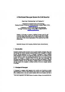
Figure 1: System overview. Each camera (Cam-1..Cam-N) is connected to a capturing server (Cap-1..Cap-N). This section gives a brief overview of the hardware and software components of the system. Figure 1 is a schematic diagram of the component parts. The blocks represent functional modules and not necessarily physical devices. For example each camera (Cam-1..Cam-N) is assigned to a (logical) capture server. Physically the capture servers are implemented using IT components, i.e. a rack-mounted PC. This PC can host a number of logical capture servers. In our recent configuration we built up a studio system with a number of HD cameras (Sony HDC-X300 and Canon XL H1) connected via HD-SDI link to the PCs. Currently two HD-streams are captured on one PC, that means two logical capture servers are running on the same hardware system. The communication and data exchange between these components is based upon a local area network. This concept provides a cost-effective way of implementing a system which can be easily configured to suit particular requirements. For example the number of cameras can be varied depending on the available space in the studio and the specific production needs. Usually the cameras are fixed and their parameters are determined with a calibration procedure. In addition, cameras equipped with a real-time tracking system or robotic controlled cameras can be used, as shown for Cam-N in figure 1. One challenge in the integration of broadcast equipment into a predominantly IT based system is the time synchronisation of both sub-systems. Broadcast equipment traditionally uses a reference video signal to synchronise (or ‘genlock’) video
A distributed multi-camera processing framework
As in our earlier system [12], the output of each camera is captured by a commodity PC equipped with a video capture card and a disk array. Unlike the earlier system, we are now capturing uncompressed high definition (HD) video1 . Each PC has a dual channel capture card, so can capture the outputs of two cameras. The PCs typically have 6 disk drives: one is used for the operating system and software, and the remaining five are configured as a RAID0 array. Using 500GByte drives we can store in excess of six hours (or three hours for two channel capture) which is enough time for even longer (experimental) shooting sessions. 3.1
Synchronisation
In our earlier system we used RS232 serial connections to send trigger signals to each capture PC. This requires each PC to have an RS232 interface. This increases the number of interconnections between machines (distribution amplifiers may also be needed) and has not proved to be reliable enough for use in a production environment. In the current system we make use of tightly synchronised PC system clocks, for example instructing all servers to start capturing at the same time instant. The PCs are synchronised using either the well known Network Time Protocol (NTP) or the IEEE 1588 Precision Time Protocol (PTP). The EBU/SMPTE task force on timing and synchronization [16] has proposed using PTP to synchronise future audio/video hardware to within 1µs. A disadvantage of PTP is that all the machines must be connected to the same ethernet switch or hub, but this is not a problem in a typical studio setup. As usual in TV production, all the cameras are ‘genlocked’ to a common source of video synchronisation signals. This ensures that the video outputs of the cameras are synchronised, so the PCs’ clocks only need to be synchronised to an accuracy of a few milliseconds. If the cameras have different internal processing delays, then although they are genlocked they will capture frames at different times. This can be compensated for by adding or subtracting a suitable offset to the PC’s clock time to generate a true capture time. Any difference between video capture cards can also be compensated for. This flexibility would be harder to achieve with the simple synchronisation line approach. 1 1920
x 1080 pixels, 8 bit in 4:2:2 YUV at 25 frames per second
The time offset between different camera channels is found experimentally by capturing a short clip of a clapperboard, then manually examining the recordings of each camera to find the frame number where the clapper closed. This sets the timing to frame accuracy – finer adjustments can be made to some cameras by setting their genlock offset. Making this adjustment would require a more sophisticated ‘clapperboard’, such as a row of LEDs that light up in sequence at millisecond intervals.
of the component’s ‘outboxes’. The Kamaelia system picks up the message and delivers it to the next component.
Every video frame is given a timestamp that represents the actual clock time when the camera captured that image, in milliseconds since the UNIX epoch – 1st January 1970. This timestamp, and other ‘metadata’, accompanies the frame (and anything derived from it, such as moving camera parameters or a 3D model) through the entire system, and allows components receiving feeds from several camera channels to be confident that they are synchronised. This is similar to, but simpler than, the time related labeling (TRL) proposed by the EBU/SMPTE task force. 3.2
Circular buffer
With the ever decreasing cost of computer memory it has become quite reasonable to store several seconds of video in a PC’s main memory. Such a buffer is useful when recording uncompressed video to disk – the data stream can be divided into suitably sized blocks, and any timing variations (e.g. disk seeking) can be accommodated. Using a large circular buffer gives us another advantage – we can start a recording a couple of seconds before the system operator hits the “record” button. This is a useful feature, for example to record incidents in sports games. Each capture process continually stores the most recent 300 frames, and their time stamps, in memory. When the operator presses “record”, a time stamp two seconds into the past is sent to the capture servers. They then record to disk every frame in the buffer that has a later time stamp. 3.3
Software framework
The system software is implemented using Python and C/C++. Python’s scripting and high-level language concept enables rapid development and easy experimentation, both desirable in an experimental system. The actual “number crunching” required to process video is programmed in C or C++, which is interfaced to Python using SWIG [2]. Python interfaces to the capture card’s SDK are also generated by SWIG. A natural paradigm for video and graphics processing is a pipeline of components, each performing a simple task but combining to form a complex system. Well known examples of this are UNIX pipes and Microsoft’s DirectShow framework. We use the Kamaelia framework [7] to create and connect such components. This framework is designed to simplify the implementation of concurrent systems. A Kamaelia component is conceptually quite simple. After initialisation it enters a loop, waiting for messages to appear in any of its ‘inboxes’. These messages typically represent a unit of work, such as a video frame to be processed. After completion of the work, any output is placed in one or more
Figure 2: Distribution of video from frame grabber to multiple destinations. Components can be connected together to form quite complex systems. They can also be dynamically created and destroyed. Figure 2 shows the core of our capture server process. At the top is a Kamaelia ‘Backplane’ component called “FRAMES”. This provides easy distribution of video to any number of ‘SubscribeTo’ components, which can be created as required. Frames are sent to the backplane by a ‘PublishTo’ component that receives them from a video grabber component. There are two server task pipelines active in figure 2: one that writes video to disk and one that sends reduced size video to a remote client via a TCP socket. This latter task is used by a controller GUI that has multiple video windows, each showing live video from a different camera, as shown in figure 3. The server creates pipelines like these in response to requests from client applications. We are using Pyro (Python Remote Objects) [9] for this client-server communication. Pyro is a lightweight system that is well suited to this application. Unlike our earlier system [12], where video frames (or processed frames such as key signals) were “pulled” from the capture servers by other parts of the system in a client-server model, we are using a “push” model: the capture servers send frames continuously to any process that has requested them. This minimises latency and reduces the likelihood of deadlocks in the system. 3.4
Strategies to cope with frame-drops
In any system as complex as this, with up to a dozen channels of HD video being captured to disk, processed and passed over networks between PCs, some thought needs to be given to what happens when network congestion or processor overload leads to some frames being dropped.
4. texture computation / preparation 5. rendering The following gives a brief description of the implementation of these modules and how they are integrated into the distributed system. 4.1
Figure 3: channels.
A simple GUI client controlling 12 camera
For example, the computation of a visual hull should use silhouettes derived from all camera channels. If any of those channels drops a frame, the visual hull computation would be incomplete for that time instance. Two strategies would be possible here: either a degraded visual hull could be computed from the available silhouettes, or the computation could be dropped entirely, skipping that time instant. This latter strategy could fail if several camera channels were dropping frames: if each channel drops different time instants there may never be a complete set from which to compute the visual hull. The solution is to ensure that each channel chooses to drop the same time instants. This is achieved by using the same frame dropping strategy in every component, where the choice of which frame to drop is based on the frames’ time stamps. In any case the server records the full video rate to (local) disk, so only live ’preview’ quality processing is affected by network congestion. Final non real time processing has the full video signal available. 4
Implementation of a free-viewpoint capture and rendering system
This section describes the implementation of a distributed 3D reconstruction and free-viewpoint rendering system using Image-based Rendering (IBR) techniques. The emphasis is on describing the system aspects and not so much the algorithmic side of the implemented methods2 . Although the system was designed for this application scenario it can be viewed as an example since other classes of applications could also be implemented with the system architecture. The image and 3D processing consists of the following steps or modules: 1. camera calibration 2. image segmentation 3. 3D reconstruction 2 more
detail on aspects of the algorithms can be found in [12]
Camera setup and calibration
As described, the system is very scalable with respect to the number of cameras used. The cameras can be arranged in an inhomogeneous, unstructured setup, allowing for example varying object distances, baselines, focal lengths or sensor sizes and resolutions. Calibration is achieved using a large planar calibration target (chart calibration) that is recorded in various poses to cover the whole volume used for reconstruction. Static cameras are calibrated once before a capture session. For non-static cameras a live calibration is used with techniques described in [20, 21]. 4.2
Image processing and 3D Reconstruction
The 3D reconstruction uses an octree-based visual hull algorithm as presented in [12]. The visual hull algorithm relies on calibrated cameras and object silhouettes, provided as segmentation images. The silhouettes are acquired through chroma keying or difference keying. This is computed in real-time on each capture server. The resulting segmentation is compressed using run-length encoding and transmitted from the server to any client via ‘push’ mode. The 3D reconstruction is implemented on a single PC, that gathers the camera calibration data and then receives and decodes the segmentation data. An alternative approach for distributing the load is described in [3]. In this paper a partial octree is computed on each capture server and then passed on to the next. This approach results in a long latency. 4.3
Rendering
The rendering of the final virtual scene requires the reconstructed 3D mesh and one or more images for texturing. Both the mesh and the image data change for every frame. A dedicated rendering PC collates the timestamped inputs for every frame and renders them using a high-end NVIDIA QuadroFX 4800 graphics card. The resulting meshes typically have only a low complexity (compared to the capabilities of modern graphics hardware) of up to 40K vertices. However, the texture images are at 1080p HD resolution and require efficient processing. To render the virtual view, texture images from original camera views are used. In the simplest and fastest case the single best matching original view is calculated based on its relative position and orientation to the virtual camera. The whole scene is then textured using only this view’s texture. This approach can cause temporal artefacts, e.g. strong discontinuities between consecutive frames when the best matching view changes. It also does not take care of object areas that were occluded or not in view in the chosen original view (spatial
artefacts). In our current setup we use a simple global selection of the best camera view, based on camera angle deviation and spatial resolution (using only object distance and sensor resolution). We aim to incorporate per-polygon blending approaches as in [6] and [10] in the future. 4.3.1
Improved rendering
To produce more realistic results, more than one view should be used. One option is to make a global blending of a small number of the best matching views using multi-texturing. This approach can take care of occluded or invisible regions, as long as they are visible in at least one of the chosen views. More sophisticated approaches were presented in [10] and [14] by determining the three best views for each individual polygon and combining them with per-vertex blending weights. The best views were chosen based only on the angle deviation between virtual and original cameras. This method however requires several pre-computations for the mesh, which may hinder its usage in a real-time environment where the mesh changes with every frame. Another approach unifies View-dependent Texture Mapping and Light Field Rendering techniques in a comprehensive analysis of the challenges and goals of Image-based Rendering [6]. This new method, called Unstructured Lumigraph Rendering, further includes terms for spatial resolution3 and the field-of-view into the computation of the blending weights. 4.4
Texture Compression
The view-dependent rendering will require more than one HDresolution video frame (typically 2 or 3) for every output frame. With a television frame rate of 25 fps this can put a lot of traffic on an IP-based network. Image data in uncompressed YUV format (4:2:2, 8 bit) with 1080p HD resolution amounts to nearly 100 MByte/s per camera. The rendering should therefore be restricted to a small number of image inputs, to avoid unnecessary data transfer costs both over the IP network and between system memory and graphics card. An additional option is to apply data compression to the transferred HD images.
ratio, whereas DXT3 and DXT5 have a 4:1 ratio. Due to its lower complexity, DXT1 is best-suited as a basis for real-time applications. Initial tests with an open-source implementation [5] of the DXT1 algorithm showed that on the server side an encoding frame rate of 10 fps is achievable on an Intel i7 machine. This is however not enough to allow use in a real-time system. A DXT-compatible texture compression algorithm for real-time applications was first presented in [24]. Further improvements with focus on high resolution material promise HD frame rates of up to 100 fps on modern Intel Xeon machines [18]. Experiments on latency in an IP-based HD transmission system (also using Centaurus II capture cards) showed that this improved DXT1 algorithm adds only about 10ms to the overall system latency [25]. Finally, DXTC algorithms using GPU-acceleration promise even higher compression speeds [1]. But adding a dedicated GPU to every capture server was deemed to be impractical, especially because of the additional latency when transferring data back from the GPU. 5 5.1
Results Studio setup
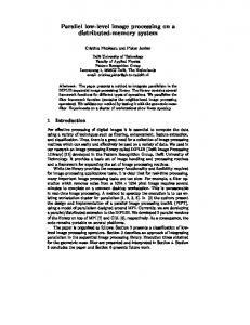
The camera setup used in the following tests is comprised of 11 HD cameras and 1 SD camera. The HD cameras are arranged in a circle inside the TV studio at various heights between 1 m and 5 m, with the additional SD camera looking straight down on the scene from a height of 5.5 m. The angle between the HD cameras varies between 17 and 65 degrees and their object distances vary from 2 m to 5 m. Figure 4 shows four views of a captured studio scene. Image segmentation is achieved with chroma keying on blue. The studio floor and walls are covered in retro-reflective cloth, which is illuminated by rings of blue LEDs that are arranged around each camera lens [12].
Traditional image compression methods add latency on both the server side and on the renderer side, for compressing and decompressing the data, respectively. An alternative approach would be to use texture compression algorithms such as S3TC (adopted by Microsoft as DXTC)[4]. DXTC is implemented in hardware on all modern graphics cards, and therefore adds only minimal decompression latency on the renderer. DXTC is a family of lossy compression algorithms. The actual output quality, speed and compression ratio depend on the used algorithm. For RGBA content DXT1 offers a 6:1 compression 3 The
spatial resolution depends on intrinsic camera parameters, such as sensor resolution and focal length, and on extrinsic camera parameters, such as object distance and obliqueness relative to the imaged surface [6].
Figure 4: Images captured with the same timestamp.
5.2
Synchronisation
We compared the synchronisation capabilities of PTP and NTP on our cluster of 8 video capture servers – 3 Dell PowerEdge 2950, 1 HP ProLiant DL180 G5 and 4 IBM x3650 7979. In both cases we used the synchronisation software’s own status reporting tools to observe the clock time offset on every machine at regular intervals. This is not the best way to obtain objective measurements, so the results are merely indicative. In the NTP setup, all machines shared the same configuration: the departmental NTP master was used as a reference server, and all the machines in the cluster were declared as peers. NTP is quite slow to converge. After 24 hours running the peak-peak time disparity between the servers was held within 1ms. In the PTP setup, NTP was used to synchronise one machine to the departmental master, and the remaining machines used the open source programme PTPd [15] to synchronise to this local master. PTP converges much more quickly. It took less than 30 minutes for the peak-peak time disparity to fall to less than 25µs. Thereafter the disparity is typically around 10µs, occasionally rising to 25µs. 5.3
Processing
The system was used to compute a 3D reconstruction from 11 cameras, in a setup as described above. The image processing (YUV to RGB conversion, chroma-keying) is running at full frame-rate (25 fps) on the capture server and passes on this data to another workstation that computes the 3D reconstruction (visual hull). At the current state an octree with a resolution of 64 x 64 x 64 (with 1-times super-sampling) is computed in real-time. This quality is good enough for preview purposes, as shown in figure 5. Recent work is looking into optimising the code to improve speed.
multiple cameras in a broadcast production environment was described. The developed time synchronisation between broadcast equipment, i.e. cameras, and the IT sub-systems is well tested and works quite reliably. Tests to compare NTP versus PTP revealed that both services can synchronise the PC clocks to an accuracy that is within an acceptable tolerance for this application. The restriction with NTP is that it needs a long time to settle and so would not be suitable for systems that are shut down and booted up on purpose, for example in a mobile application outside a studio. PTP on the other hand is quick to synchronise a group of computers sharing one network switch or hub, and achieves closer synchronisation. However, it does not work over a wider area network, so NTP is still the protocol of choice here. PTP is not yet as established as NTP, which is installed by default with many operating systems. The implemented, distributed real-time processing system is very flexible and allows integration of new hardware and software components. This integration is relatively easy due to the use of the high-level programming language Python and the Kamaelia framework. The discussed application of real-time free-viewpoint capture and rendering is ongoing work and mainly used here to demonstrate the concepts of the distributed system. Further research will examine the effect of texture compression on the overall end-to-end latency (from capture to rendering) of this IT based system. Our immediate interest is in achieving real-time rendering of reconstructed views using a temporally and spatially consistent view-dependent texturing algorithm. 7
Acknowledgements
This work has been funded by the UK TSB as part of the i3DLive project. References [1] Real-time DXT compression; NVIDIA texture tools. http://code.google.com/p/nvidia-texturetools/wiki/RealTimeDXTCompression. [2] David M. Beazley and William Fulton. http://www.swig.org/.
Figure 5: Reconstructed mesh with simple texturing and wireframe of the mesh.
6
Conclusions
In this paper a software and hardware framework for the implementation of distributed processing applications using
SWIG.
[3] E. Borovikov and L. Davis. A distributed system for realtime volume reconstruction. In CAMP ’00: Proceedings of the Fifth IEEE International Workshop on Computer Architectures for Machine Perception (CAMP’00), page 183, Washington, DC, USA, 2000. IEEE Computer Society. [4] Pat Brown. EXT texture compression s3tc Version 1.5. http://opengl.org/registry/specs/EXT/ texture compression s3tc.txt. [5] Simon Brown. http://code.google.com/libsquish/.
[6] Chris Buehler, Michael Bosse, Leonard McMillan, Steven J. Gortler, and Michael F. Cohen. Unstructured lumigraph rendering. In Eugene Fiume, editor, SIGGRAPH 2001, Computer Graphics Proceedings, pages 425–432. ACM Press / ACM SIGGRAPH, 2001. [7] Kamaelia Contributors. Kamaelia - concurrency made useful, fun. http://www.kamaelia.org/. [8] George Coulouris, Jean Dollimore, and Tim Kindberg. Distributed Systems: Concepts and Design. AddisonWesley, 2001. [9] Irmen de Jong. pyro - Python Remote Objects. http://www.xs4all.nl/ irmen/pyro3/. [10] Paul E. Debevec, George Borshukov, and Yizhou Yu. Efficient view-dependent image-based rendering with projective texture-mapping. In Proc. of 9th Eurographics Rendering Workshop, Vienna, Austria, June 1998. [11] Oliver Grau. A 3D production pipeline for special effects in tv and film. In Mirage 2005, Computer Vision/Computer Graphics Collaboration Techniques and Applications, Rocquencourt, France, March, 2005. INRIA. [12] Oliver Grau, Tim Pullen, and Graham A. Thomas. A combined studio production system for 3-d capturing of live action and immersive actor feedback. IEEE Transactions on Circuits and Systems for Video Technology, 14(3):370–380, March 2004. [13] Oliver Grau, Graham A. Thomas, A. Hilton, J.Kilner, and J.Starck. A robust free-viewpoint video system for sport scenes. In Proc. of 3DTV-Conference, Kos island, Greece, May 2007. [14] Celso Kurashima, Ruigang Yang, and Anselmo Lastra. Combining approximate geometry with view-dependent texture mapping - a hybrid approach to 3D video teleconferencing. In Proceedings of XV Brazilian Symposium on Computer Graphics and Image Processing (SIBGRAPI 2002), pages 112–119, Fortaleza-CE, Brazil, October 2002. [15] George Neville-Neil and Steven Kreuzer. http://ptpd.sourceforge.net/.
PTPd.
[16] EBU/SMPTE Task Force on Timing and Synchronization. Request for standardization. Technical report, EBU/SMPTE, August 2009. [17] P. Rander, P.J. Narayanan, and T. Kanade. Virtualized reality: Constructing time-varying virtual worlds from real events. In Proceedings of IEEE Visualization ’97, pages 277–283, October 1997. [18] Luc Renambot, Byungil Jeong, and Jason Leigh. Realtime compression for high-resolution content. In Proceedings of the Access Grid Retreat 2007, Chicago, IL, 2007. University of Illinois at Chicago.
[19] William R. Sherman and Alan B. Craig. Understanding Virtual Reality: Interface, Application, and Design. Morgan Kaufmann, 2002. [20] Graham A. Thomas. Real-time camera pose estimation for augmenting sports scenes. In Proc. of 3rd European Conf. on Visual Media Production (CVMP2006), pages 10–19, London, UK, November 2006. [21] Graham A. Thomas, J. Jin, T. Niblett, and Urquhart. A versatile camera position measurement system for virtual reality tv production. In Conference Proc. of International Broadcasting Convention, pages 284–289, Sept. 1997. [22] P.N. Tudor and S.H. Cunningham. Improving workflow in practice for low-cost programme-making using mxf & aaf file formats. In Proc. of NAB, 2006. [23] M. Valera and S. A. Velastin. Intelligent distributed surveillance systems: A review. IEE Proceedings Vision, Image and Signal Processing, 152(2):192–204, April 2005. [24] J.M.P. van Waveren. Real-time DXT compression. May 2006. [25] Ian Wesley-Smith, Miloˇs Liˇska, and Petr Holub. Implementation of DXT compression for UltraGrid. Technical Report 4, CESNET, June 2008.


![[PDF] Sound Capture and Processing - Google Sites](https://m.moam.info/img/260x300/pdf-sound-capture-and-processing-google-sites_647704b4097c474b228b77f4.jpg)