Problem Frames: a Case for Coordination L. Barroca1, J.L. Fiadeiro2, M. Jackson1, R. Laney1 and B.Nuseibeh1 1
Department of Computing, The Open University Milton Keynes MK7 6AA, UK {l.barroca,r.c.laney,m.jackson}@open.ac.uk 2
Department of Computer Science, University of Leicester University Road, Leicester LE1 7RH, UK
[email protected]
Abstract. We show how principles of separation of Coordination from Computation can be used to endow the Problem Frames approach to problem analysis with representation schemes. These representation schemes facilitate the way evolution of requirements or of the application domain can be reflected in the decomposition structure, making it easier to change.
1
Introduction
Decomposition as an aid to tackle complexity has been used in software development for a long time; after all, software engineering is a human activity and problem solving through "divide-and-conquer" must be as old as humanity. Many approaches to decomposition can be found in the literature, some of which have got into day-to-day practice, from domain modelling down to design. However, problem domains can change over time: changes in the application domain may require software solutions to be changed to maintain customers’ expectations. Even when the application domain remains stable, customers come up with new requirements that often necessitate new solutions to be developed! This means that problem analysis and decomposition are essentially part of a continuous process. Indeed, even if a problem decomposition structure succeeds in breaking down the complexity of a problem and allows a suitable solution to be developed, such a structure may not be easy to evolve as the original problem and its requirements change. Finding a problem decomposition that can evolve easily is often difficult - unfortunately, we do not need to go back very far in history to observe situations of "conquest" through "division" that have left in place structures that have evolved in undesirable ways … A good knowledge of the problem domain, of the type of changes that are likely to occur, and of their frequency, is, again, fundamental for knowing the costs of evolution. Therefore, it is important that mechanisms be provided for changes to be reflected incrementally in the decomposition structure. This allows these changes to be tracked down to sub-problems, where they can be localised with-
out affecting the rest of the structure, or through the addition of sub-problems that reflect the new properties that need to be brought about and the way they relate to the existing ones. In this paper, we report on the work through which we are addressing this problem by extending and combining the Problem Frames approach to problem analysis and description [13] with the coordination-based approach to run-time software evolution [3]. This extension endows Problem Frames with representation structures that allow for forms of problem decomposition that separate aspects related to the coordination of the interactions between solution (called the Machine) and problem domain, from the computational aspects that the machine implements. This principle of separation of concerns has been proposed for software design in the form of Coordination Languages and Models [10]. Our contribution in this paper is the application of this principle to problem analysis and requirements specification in order to control the complexity of managing evolution resulting from changes in customers’ requirements or the application domain. We achieve this separation by the explicit externalisation of the coordination aspects, the coordination interfaces, and the explicit representation of the interactions with coordination rules. The paper is structured as follows. Section 2 provides an overview of Problem Frames and presents the example that we use throughout the paper to illustrate our approach. In Section 3, we delimit the scope of our work and introduce the proposed application of coordination primitives and modelling techniques. Section 4 shows how assumptions about the domain can be captured through coordination interfaces. Section 5 takes these coordination interfaces and discusses the description of the behaviour of the Machine through coordination rules. In Section 6, we summarise the impact of our approach in the context of related work. Section 7 concludes the paper and discusses future work.
2
Problem Frames
The Problem Frames approach to problem analysis and description recognises that domain problems can usually be categorised as a set of commonly occurring patterns for which the same type of models can be used. The approach emphasises the relationships of systems to the real world domains where they live. Problem Frames encapsulate both real world and system objects, and describe the interactions between them. A simple problem frame is represented typically by a context diagram (Figure 1) showing one machine, one domain, and the shared phenomena between them.
Figure 1: A simple problem frame
–2–
The Machine Domain represents the piece of software that the customer requires and the platform on which it executes in order to bring about some desired effects. The Problem Domain is that part of the world in which those effects are perceived by the customer. The Requirements are the properties that the customer wants to observe, through the shared phenomena b, in the Problem Domain as a result of the effects brought about by the software as it executes and interacts with the domain via the shared phenomena a. We illustrate this using a simple example of a sluice gate control introduced by Jackson [13]: A rising and falling gate is used in an irrigation system. A computer system is needed to control the gate. The gate is opened and closed by rotating vertical screws controlled by clockwise and anticlockwise pulses. There are sensors at the top and bottom of the gate travel indicating when the gate is fully opened and fully shut. The sluice gate control we look at is a timed one: A timed sluice gate is required to be in the fully opened position for ten minutes in every three hours and otherwise kept closed. Problem analysis is essentially concerned with the description of the relationships among the phenomena that are shared between these different domains: a for the phenomena shared between the Machine and the Problem Domain; b for the phenomena of the Problem Domain that the Customer can observe. In the example, the Problem Domain is clearly concerned with the gate, its motor, and the way it can be observed and operated. The Machine, i.e. the computer system that is needed to control the gate, shares with the Problem Domain the two events that it controls – the commands for opening and closing the gate as made available through the motor – and the observations of the state of the gate as made available through the sensors – being fully up or down (altogether denoted a2 in Figure 2). These two observations are also shared with the customer (denoted b2 in Figure 2). Because the sluice gate that we will be analysing is a timed one, a timer should also be made part of the problem domain. The machine observes and resets the timer (a1 in Figure 2) and the timer can also be observed by the customer (b1 in Figure 2). The machine observes and controls the sluice gate (a2 in Figure 2) and the sluice gate can be observed by the customer (b2 in Figure 2). a1
Timer
b1 Sluice Regime
Machine a2
G&M
b2
Figure 2: Problem frame for a timed sluice gate
–3–
The separation that Problem Frames provide between the different domains is particularly important during evolution. The relationship between the Machine Domain and the Problem Domain is one that the software engineering activity targets and controls. As software does not degrade in a physical sense, the need for evolving the machine will result from changes occurring in the Customer's Requirements or the Problem Domain. Changes in customer requirements are a fact of life, even an intrinsic characteristic of software systems according to Lehman [19]. It is often hard for the customer to foresee all the consequences that a Machine will have in the Problem Domain and, therefore, a newly installed machine may lead to new properties of the Problem Domain that, in turn, may lead to a revised set of customer requirements. On the other hand, the Problem Domain can change in ways that are not under the control of the Machine, which means that the behaviour of the Machine in the new domain no longer satisfies the customer requirements. Naturally, these two scenarios are not mutually exclusive; they just distil two simple situations that lead to the need to change the Machine. This paper is concerned with the problem of finding representations of the interaction between the machine and the part of the domain that it observes and controls, in ways that allow for evolution to be managed or even programmed. These representations provide a means of ensuring that the machine can self-adapt to certain classes of change known to occur in the application domain. The principle of separating coordination from computation plays a fundamental role here.
3
The Scope for Coordination
Coordination is intrinsic to the way Problem Frames are used to decompose and analyse problems. The Machine is a computational device that is superposed on the domain so that, through the interaction between Machine and Domain, new behaviour can emerge to satisfy user requirements. The computations of the Machine are of interest only to the extent that, when interacting with the domain, they enable the required properties to emerge. Hence, the central concern for evolution must be the explicit representation of the mechanisms that are responsible for the coordination of the interaction between the Machine and the Domain. In order to motivate the approach that we propose in this paper, let us refine the diagram in Figure 1. The purpose of the diagram was to note the need to distinguish between three domains and the relationships that concern them. Software engineering works on descriptions of the entities, phenomena, and properties that are involved in these domains and relationships [14]. So, the machine and the relationship a have to be developed and established based on a model of the relevant part of the domain. On the other hand, and perhaps not as obvious, the relationship a does not need to be established on the basis of the concrete software system code (computation) that is executing, but of a description of its behaviour (specification) as it is executed on the chosen platform. The specification is essential because it encapsulates changes that do not have any bearing on the customer's requirements as formulated. These are modifications that software engineers may wish or be required to perform on the
–4–
machine in order to take advantage of new technologies or to respond to IT infrastructure changes Figure 3 depicts the wider software development context, in which the dashed line separates the domains and their descriptions:
A
M fM
D fD
Figure 3: Enriched problem frame diagram By M we mean the description of the behaviour of the execution of the software system on a particular platform. This description is based on the shared phenomena identified in a and other parameters that relate to nature of the formalism that is being used for describing the behaviour. These additional parameters are not features of the code that lies in the Machine, but mere "prosthesis". By D we mean the model that abstracts the properties of the Problem Domain that concern the way the Machine can interact with it, and by A we denote the way descriptions M and D are related. This is where we separate coordination from computation: in A/D we wish to place all and only the aspects that concern the way the machine interacts with the domain. These include the phenomena through which this interaction takes place, and the assumptions on which it is based, i.e. the properties that are assumed of the domain in the way the computations taking place in the Machine are programmed. This explicit externalisation of the coordination aspects, which we call the coordination interface of the Machine, is the contribution that we claim and discuss in section 4 of the paper. The vertical relationships between the description and the domain worlds also play a central rôle in our approach. By fM we mean the fit that needs to exist between the description and the behaviour being described. This fit can be the object of formal verification once the description M is translated to an acceptable semantics for the language/platform in which the Machine is coded. It is the responsibility of the software provider to ensure fM throughout the life of the system. In contrast, customer satisfaction is established exclusively on the basis of the triple M/A/D and therefore fM is not within the scope of the kind of evolution that we are addressing. Therefore, we will not discuss fM any further in this paper. By fD we mean the fit between the model and the Problem Domain. Depending on the nature of the domain that the software system is controlling, this fit may or not be
–5–
of a formal nature. For instance, the Machine may be controlling another software system (e.g., monitoring some of its properties), in which case fD can be cast in a semantic domain common to the two language/platform couples. Because, again, the satisfaction of the customer's requirements is established on basis of the triple M/A/D alone, the customer can only observe the required properties in the Problem Domain if the fit is correct. Maintaining the correctness of fD is a hard problem as discussed in [15]. It is not part of the responsibility of the software engineer; otherwise it would be part of the Problem Domain. Rather, it is the responsibility of the problem analyst. Indeed, one of the reasons a given system may need to evolve is, precisely, because its boundary with the Problem Domain may be required to change in order for some parts of the environment to become under its control. For instance, new sensors may be introduced that allow the software system to monitor part of the fit and react when deviations occur [14]. What is important is that the control of the correctness of fD is an activity that may require a change of the original problem and, hence, of the frames that apply, bringing fD, or part of it, into the realm of the problem domain. In any given state of the decomposition, the fD in place is not under the control of the Machine and, hence, will remain outside the scope of the paper. In summary, we are concerned with the representation of the triple M/A/D. It is at this level that the satisfaction of the customer's requirements can be established. These requirements should be expressed in a logical formalism (L, | ) as a sentence R. On the other hand, a mapping R (M/A/D,fD) into L should be provided that is correct with respect to the semantics of (L, | ) and the language in which M is described, characterising customer satisfaction as:
–
–
R(M/A/D,fD), G |– R
†
where G represents properties † of the domain that can provide an adequate bridge between the phenomena at a and the phenomena at b. The truth of G will be independent of the problem being analysed and hence used as an evolution invariant. Any † formalisation of the properties of a physical domain is an approximation to the truth, and different approximations are appropriate for different problems, of course. One may very well need to evolve the triple due to changes in G that arise from the realisation that the approximations being made are not good enough or valid anymore (e.g., relativistic considerations may become relevant in a domain previously described in purely Newtonian mechanics). We leave a more detailed discussion of these issues to a future paper. Our approach to the representation of the coordination aspects involved in Problem Frames is based on the coordination technologies presented in [3]: a set of principles and modelling techniques that were first proposed in [2] based on the notion of coordination contract, or contract, for short. The purpose of coordination contracts is to make available in modelling languages, like the UML [5], the expressive power of connectors in the terminology of Software Architecture [23]. The overall goal is to provide a means for the interaction mechanisms that relate system components to be externalised from the code that implements these components. It makes the relation-
–6–
ships explicit in system models so that they can be evolved independently of the computations that the components perform. Contracts prescribe certain coordination effects (the glue of architectural connectors in the sense of [1]) that can be superposed on a collection of partners (system components) when the occurrence of one of a set of specified triggers is detected in the system. Contracts establish interactions at the instance level when superposed on a running system. In the terminology that we used in the previous section, they sit in the Machine domain as part of the code. At the level that concerns us in the paper, the triple M/A/D, the primitive that abstracts the properties of the coordination glue from the code that implements it in contracts, is called a coordination law as described in section 5. A coordination law corresponds to a connector type as in Architecture Description Languages. In business modelling, coordination laws can be used to model the rules according to which organisations make available to the market the services that their core entities provide [16,17]. In control systems, they can be used to model the mechanisms that need to be superposed over the components of the target plant to monitor their behaviour, adapt them to new modes of operation, or interconnect them to ensure required emergent behaviour [4]. In the description of a coordination law, the nature of the components over which the law can be instantiated are identified as coordination interfaces (the roles of the connector type in the sense of [1]). Our approach is to capture each problem frame triple M/A/D as a coordination law for which M corresponds to the glue, D defines a coordination interface, and A is captured in the way the interface is used in the law.
4
Domain Assumptions as Coordination Interfaces
We now illustrate our approach by returning to the timed sluice gate example in section 2. Let us deal first with the way the domain model is abstracted as a coordination interface. The idea is to declare what the Machine is expecting from the problem domain in the way it has been designed to control it. Two primitives are made available in coordination interfaces for that purpose: services and events. • Services identify operations that the domain must provide for the Machine to invoke. In our example, these correspond to the actions that the motor makes available to operate the gate – onClockw for starting the motor clockwise, onAnti for starting it anticlockwise, and off for stopping it. • Events identify state transitions that the Machine needs to be able to detect in the problem domain. These act as triggers for the contract that is being put in place to react and activate a coordination rule as discussed below. In our example, the events correspond to the states that the sensors of the gate make available – top and bottom – so that the Machine knows when the motor has to be stopped.
–7–
coordination interface sluice_gate services onClockw, onAnti, off events top, bottom properties (onClockw ⁄ onAnti) … (¬(onClockw ⁄ onAnti) before off) onClockw … (top unless off) onAnti … (bottom unless off) end interface
This example also illustrates that coordination interfaces are not just declarations of features (signatures). They specify properties that must be proved upon instantiation, i.e. express requirements on the behaviour of the components that can come under the coordination of the machine. These properties capture semantic aspects of the roles that components play in the application domain. Such properties are defined so as to state requirements placed by the law on the entities that can be subjected to its coordination rules, not as a declaration of features or properties that entities offer to be coordinated. In our application to Problem Frames, these are assumptions made on the problem domain that determine the correctness of the fit fD. Returning to our example, we chose three properties to illustrate the kinds of assumptions that can be made and the implications that they have. • The first reads: "After an onClockw or an onAnti command is accepted, no more such commands will be accepted before an off command is accepted". In physical terms, this means that the domain couple Gate&Motor is being assumed to prevent these events from occurring. One may think, for instance, of a motor that provides three buttons, one for each operation, and that the onClockw and onAnti buttons become locked once pressed and will only be unlocked after the off button is pressed. • The second reads: "After the onClockw button is pressed, the event top will be eventually observed unless the off button is pressed in the meanwhile”. In other words, if the motor is started clockwise and left undisturbed for long enough, the event top will eventually be observed through the sensors. • The third is similar to the second; it states that if the motor is started anticlockwise and left undisturbed for long enough, the event bottom will be eventually observed through the sensors. The language that we have used for specifying these properties is that of a temporal logic, the syntax and semantics of which we shall not discuss in the paper because they are not relevant for understanding our approach (see [21] for examples of temporal logics typically used in Computer Science). In [3], an alternate to temporal logic that uses pre/post conditions on services is illustrated. The implications of including properties such as these in a coordination interface have to be understood in the context of the triple M/A/D. They are taken in conjunction with the properties of the Machine to ensure the satisfaction of the requirements. Hence, they provide the criteria for the fit fD to be judged. That is to say, these are properties that need to be checked when the machine is installed in the domain. They result from an agreement between the problem analyst and the customer as to the nature of the problem domain over which the machine is going to operate.
–8–
From the point of view of the software engineer, these are properties that can be assumed when designing the machine. Hence, in our example, the software engineer will not bear any responsibility for the behaviour of the machine if it is interconnected with a sluice-gate that allows for buttons to be pushed indiscriminately. A software engineer who builds a machine that relies on the observation of the top event to switch off the engine after having set it clockwise, cannot be blamed if the motor burns down because the sensor that should emit the top event is faulty. Hence, the more properties are included in a coordination interface, the simpler the task of programming the computations on the machine will be, which can turn to the customer's advantage as reduced development costs. However, this comes at the cost of controlling that the fit fD is maintained correct which, as already argued, is to be born by the customer, not the software engineer. It is the customer's responsibility to make sure that the sensors are working properly and that only motors that do not allow for buttons to be pushed indiscriminately are used. If, for instance, this assumption on motors ceases to be sensible, for instance because motors of that kind are no longer available, then the problem analyst should be brought in to renegotiate the original problem frame, which may lead to a new triple M/A/D to be developed. Because the operation of the sluice gate needs to be timed, we have to account for a timer as well. The timer needs to provide a service for being reset and events that report elapsed time – tick(n:nat). coordination interface timer services reset events tick(n:nat) properties tick(n) … (¬tick(m) before (tick(n+1) ⁄ reset)) reset … tick(0) end interface
In this case, the properties are specifying that the ticking should be incremental and sequential until the timer is reset, starting with 0. Again, the software engineer will bear no responsibility for the outcome of a connection of the machine with a timer that decrements or is not sequential. This example also illustrates how coordination interfaces can be used for identifying not only the features of the domain through which required forms of coordination are going to be superposed, but also components that need to be provided in addition to the Machine. Such components, like the timer, are not necessarily part of the original problem domain – the Gate&Motor does not necessarily come with an integrated timer or clock – nor of the solution domain – the timer is not to be realised by software. They need to be provided at configuration time, and they may be evolved independently of the Machine and changes operated in the application domain, provided that the fit to the coordination interface is maintained. Coordination interfaces are named for the sake of reusability and simplification of the binding process that establishes the fit fD. Their actual names are not important. Our experience in using these coordination primitives in real projects has shown that it is useful to externalise coordination interfaces from the laws in the context of which they are defined, to establish a hierarchy between them that is consistent with the fD relationship in the sense that a fit to a given interface is also a fit to any ancestor of
–9–
that interface. In business environments, this is useful because coordination interfaces fulfil the role of representations of abstract business entities and, hence, the hierarchy of interfaces will, ultimately, provide a taxonomy of all the business uses that are made of entities in the application domain. For control based systems, the hierarchy of interfaces can be mapped to an existing classification of the component types that can be found for the target plant, allowing a component to be replaced by a more specialised one without destroying the fit that binds it to the controller.
5
Describing Machine Behaviour through Coordination Rules
The effects that the software system is required to bring about are described through the coordination rules of the law that describes the behaviour of the Machine: coordination law timed_sluice_gate_controller interfaces
sg: sluice_gate; tm:timer
attributes
open: bool
rules
when sg.top do sg.off || open:=true || tm.reset when tm.tick(10) Ÿ open do sg.onAnti when sg.bottom do sg.off || open:=false || tm.reset when tm.tick(170) Ÿ ¬open do sg.onClockw
end law
Each coordination rule is of the form: when trigger with condition do set of operations
Under the “when” clause, the trigger to which the contracts that instantiate the law will react is specified as a Boolean condition defined over the events declared in the interface and conditions over the internal state of the law. Under the “with” clause we specify a guard, a Boolean condition defined over the internal state of the law that, if false, leads to a rejection of the trigger; this means that the reaction will not be executed and, depending on the nature of the trigger, failure will be reported back to the domain entity for suitable handling. The reaction to be performed is identified under the “do” clause as a set of operations, each of which is either a service declared in the interface or an update on the internal state of the law. The whole interaction is handled as a single transaction, i.e. its execution is atomic. In particular, multiple assignments are executed by using the values of the attributes before the occurrence of the trigger.
– 10 –
In our example, none of the rules are guarded. Intuitively, this is because the gate is not proactive: it does not invoke the controller; it is the controller that reacts to the observations it makes of the sensors and timer. The example also shows that it is possible to declare features that are local to the law itself such as attributes that facilitate the definition of the scheduling of the different rules. As already mentioned, these are just a prosthesis that relates to the nature of the formalism that is being used for describing the behaviour of the Machine; they are not features that are required of the code that lies in the Machine and, therefore, can be ignored by the fit fM. In fact, we are also working on more abstract notions of machine that are more descriptive, less prescriptive, but this is not an essential aspect for understanding the approach that we are proposing. The value of the Boolean attribute open must not, of course, be confused with the Boolean value “Sluice Gate is fully open”. The former is a tiny model domain constructed to act as a model or surrogate for the latter. When more than one trigger is true, the guards ("with"-conditions) of the corresponding rules are evaluated and the trigger fails if any of them is false. If all the guards are true, the union of all reactions is performed, again as an atomic action. Notice that, in case of conflicting assignments being brought into the same synchronisation set, the reaction fails. Finally, we must point out that nothing in the description of the law is intrinsic to the sluice-gate. Although we named services and events in a way that relates them directly to the problem domain, these names do not provide any binding to the entities of the domain that the Machine is intended to control: the connection to the problem domain always needs to be made explicit through the fit fD. This is strictly enforced by the semantics of the coordination approach [9], which is justified by the principle that all interactions should be made explicit. The fits are applied at configurationtime in what in [3] are called coordination contexts, as part of a process that manages the evolution of the global system. Our discussion of coordination laws addresses analysis-time, i.e. it concerns the modelling and analysis of machines for given problem frames but not the actual deployment of instances of such machines to control given domain entities. This principle of explicit representation of interactions supports our use of coordination laws as generic descriptions of solutions that can be used for different problem frames. For instance, the coordination law above describes a simple two-cycle timer, which can be captured by a more neutral choice of names such as: coordination interface two_action&sensor services up, down, off events top, bottom properties (up ⁄ down) … (¬(up ⁄ down) before off) up … (top unless off) down … (bottom unless off) end interface coordination law two_cycle_controller interfaces
mc: two_action&sensor; tm: timer;
parameters
one,two:nat
– 11 –
attributes
open: bool
rules
when mc.top do mc.off || open:=true || tm.reset; when tm.tick(one) Ÿ open do mc.down; when mc.bottom do mc.off || open:=false || tm.reset when tm.tick(two) Ÿ ¬open do mc.up
end law
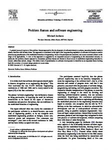
Its application to the sluice-gate problem consists of the instantiation of the parameters one and two with values 10 and 170, respectively, the fit fG&M, which should map up to onClockw, down to onAnti, and off to off, and a fit fT to a physical timer.
timer
two_cycle_ controller (10,170)
fT
two_action &sensor fG&M
Gate&Motor
Figure 4: Generic coordination law and its application to the sluice gate This example was chosen to illustrate another feature of coordination laws. Besides the declaration of attributes for structuring an (abstract) internal state, parameters can also be defined that are controlled by the environment. These are just examples of services that the law can declare as part of its public interface: besides parameters that can be set, we may include operations that act on the internal state and some of the services that it gets from the components through the fits. We should also stress the fact that a fit fM needs to be established for each target platform. Each time a technological change is introduced, it makes it necessary for the Machine to be redeployed. The binding mechanism is also likely to have to change accordingly and, hence, the fit needs to be re-established.
6
Related Work
In the previous sections, we have discussed primitives for representing explicitly, in Problem Frames, the coordination aspects that concern the interaction between the Machine and the Problem Domain. The Machine can be evolved without compromising satisfaction of user requirements. Also, changes in the application domain can be detected at the levels of the interface that connects the Machine with the domain
– 12 –
and not at the level of the computations that implement the services offered by the Machine. As far as we know, this is one of the first attempts at bringing together problem decomposition approaches to requirements specification and principles of separation of concerns that have been typically used for software design; this is an effort that, in our opinion, will allow us to contribute towards taming the complexity of evolving software applications according to the changes that occur in the problems that they are meant to solve. Indeed, on the one hand, there are only a few other general approaches to decomposing problems rather than solutions. Notable exceptions are the goal-based approaches of KAOS [18] and the NFR framework [7]. However these two approaches are not immediately suited to the separation of concerns that our coordination approach promotes, as they do not concentrate on domain properties in the same pervading manner as Problem Frames. On the other hand, composition of software artefacts on the basis of separation of concerns has been addressed by a range of aspect-oriented techniques [8]. However with the notable exception of [11] and [24], aspect-based approaches, whilst good at addressing design and implementation issues, are weak with regards to requirements, and in particular their decomposition. The approaches of [11] and [24] are mainly concerned with reconciling conflicts between a range of non-functional requirements and do not fully address decomposition of functional requirements. Furthermore, aspect-oriented techniques are too tightly coupled with object-oriented and component-based technologies to sustain the degree of generality of approaches to problem decomposition of Problem Frames. There is also little work relating requirements and architecture, exceptions include [5,6]. However, those works do not fully address problem decomposition. Ultimately we see our approach encompassing an iterative approach to requirements and architecture [22]. In this respect, our previous work on mapping solution space artifacts to the problem space complements the approach of this paper [12].
7
Conclusions and Further Work
We have shown the application of separation of concerns to problem analysis and requirements specification. Our contribution has been to add representation structures to Problem Frames in order to control the complexity of managing evolution. The coordination primitives that we described fit well into the Problem Frames approach to decomposition, which itself is substantially different from what is normally found in traditional Software Engineering. Traditional decomposition assumes a preestablished structure or architecture into which the parts identified in the decomposition are fitted as they are successively identified. This means that each part needs to conform to the modes of interaction that this structure subsumes, say remote procedural calls of given services, or reading and writing of sequential data streams, which do not necessarily reflect requirements that derive from the problem domain and, therefore, introduce unnecessary bias. Our modelling primitives provide precise,
– 13 –
means for the coordination of interactions to be separated from the way they get encoded in the computations by the Machine. Although the paper focused on the relationship between the Problem Domain and the Machine, there are other levels at which coordination can be exploited to take advantage of the way requirements are captured and evolved with Problem Frames. One of the advantages is that different requirements, leading to different Problem Frames, can be represented through different coordination laws. Thus, a typical andcomposition of requirements corresponds to a typical parallel composition of the machines that enforce them in ways that do not have to be pre-determined by earlier design decisions. In Problem Frames, decomposition is carried out by making few or no explicit assumptions about the mechanisms by which each machine may interact with others. Because the coordination approach is based on the externalisation of interactions and the dynamic superposition of the connectors that coordinate them, each machine can be described and developed by assuming no more than that is a solution to a subproblem. Composition concerns can be addressed at configuration time, i.e. when the different machines need to be brought together as a global solution to the top-level problem. Deferring composition concerns until the different sub-problems have been well identified and understood is a key feature of Problem Frames. In our opinion, this is well justified given that we consider that composition is not a static, compile-time problem of linkage, but a dynamic process that needs to be subjected to its own rules. The coordination approach goes somewhat further by advocating an explicit separation between the two concerns and providing specific primitives to model configuration and evolution. Indeed, there is further added value of the application of coordination techniques to problem decomposition: dynamic assembly and integration of requirements can benefit from existing reconfiguration techniques [20]. The work described in this paper has opened up a variety of opportunities for further work. We are currently building on previous work on composition [25,26] to provide better control on the complexity of software evolution. On the other hand, the mathematical foundations of the coordination-based approach to architectures are pretty well established by now (see [9] for a summary). They make it possible to provide a uniform semantics for the notation that was presented for interfaces and laws. They also provide reasoning mechanisms that support the derivation of emergent properties arising from composition and correctness checking of realisations.
Acknowledgements The second author would like to thank his colleagues L.Andrade (ATX Software SA), A.Lopes (University of Lisbon), and M.Wermelinger (New University of Lisbon), with whom he developed much of the work around “Coordination” that was used in this paper.
– 14 –
References 1. R.Allen and D.Garlan, "A Formal Basis for Architectural Connectors", ACM TOSEM, 6(3), 1997, 213-249. 2. L.F.Andrade and J.L.Fiadeiro, "Interconnecting Objects via Contracts", in R.France and B.Rumpe (eds), UML'99 – Beyond the Standard, LNCS 1723, Springer-Verlag 1999, 566-583. 3. L.F.Andrade and J.L.Fiadeiro, “Architecture Based Evolution of Software Systems”, in M.Bernardo & P.Inverardi (eds), Formal Methods for Software Architectures, LNCS 2804, Springer Verlag 2003, 148-181. 4. L.F.Andrade, J.L.Fiadeiro, A.Lopes and M.Wermelinger, “Architectural Techniques for Evolving Control Systems”, in Formal Methods for Railway Operation and Control Systems, G.Tarnai & E.Schnieder (eds), L'Harmattan Press 2003. 5. D.Berry, R.Kazman and R.Wieringa (eds), Proceedings of Second International Workshop from Software Requirements to Architectures (STRAW’03), Portland, USA, 2003. 6. J.Castro and J.Kramer (eds), Proceedings of First International Workshop from Software Requirements to Architectures (STRAW’01), Toronto, Canada, 2001. 7. L.Chung, B.A.Nixon, E.Yu and J.Mylopoulos. Non-Functional Requirements in Software Engineering. Kluwer Academic Publishers, 2000. 8. T.Elrad, R.Filman and A.Bader (Guest editors). Special Issue on Aspect Oriented Programming. Communications of the ACM 44(10) 2001. 9. J.L.Fiadeiro, A.Lopes and M.Wermelinger, “A Mathematical Semantics for Architectural Connectors”, in Generic Programming, R.Backhouse and J.Gibbons (eds), LNCS 2793, Springer-Verlag 2003, 190-234. 10. D.Gelernter and N.Carriero, "Coordination Languages and their Significance", Communications ACM 35(2), 1992, 97-107. 11. J.Grundy, "Aspect-Oriented Requirements Engineering for Component-based software systems", in Fourth IEEE International Symposium on Requirements Engineering (RE’99). IEEE Computer Society Press 1999. 12. J.G.Hall, M.Jackson, R.C.Laney, B.Nuseibeh, L.Rapanotti, “Relating Software Requirements and Architectures using Problem Frames”, IEEE Proceedings of RE 2002, 2002. 13. M.Jackson, Problem Frames: Analysing and Structuring Software Development Problems, Addison Wesley 2000. 14. M.Jackson, "Some Basic Tenets of Description", Software System Modelling 1, 2002, 5–9. 15. M.Jackson, "Why Software Writing is Difficult and Will Remain So", in J.Fiadeiro, J.Madey and A.Tarlecki (eds), Information Processing Letters Special Issue in Honour of Wlad Turski 88(1-2), 2003. 16. G.Koutsoukos, J.Gouveia, L.Andrade and J.L.Fiadeiro, “Managing Evolution in Telecommunications Systems”, in New Developments on Distributed Applications and Interoperable Systems, K.Zielinski, K.Geihs and A.Laurentowski (eds), Kluwer Academic Publishers 2001; 133-139. 17. G.Koutsoukos, T.Kotridis, L.Andrade, J.L.Fiadeiro, J.Gouveia and M.Wermelinger, “Coordination technologies for business strategy support: a case study in stock-trading”, in R.Corchuelo, A,Ruiz and M.Toro (eds), Advances in Business Solutions, Catedral Publicaciones 2002, 45-56. 18. A. van Lamsweerde, "Goal-Oriented Requirements Engineering: A Guided Tour", in Proceedings of the 5th International Symposium on Requirements Engineering (RE’01), IEEE Computer Society Press 2001, 249-261.
– 15 –
19. M.Lehman, "Uncertainty in Computer Application", Communications ACM 33(5), 1990, 584 - 586 20. J.Magee and J.Kramer, "Dynamic Structure in Software Architectures", in 4th Symp. on Foundations of Software Engineering, ACM Press 1996, 3-14. 21. Z.Manna and A.Pnueli, The Temporal Logic of Reactive and Concurrent Systems, Springer-Verlag 1991. 22. B.A.Nuseibeh, “Weaving Together Requirements and Architecture”, IEEE Computer 34 (3):115-117, March 2001. 23. D.Perry and A.Wolf, "Foundations for the Study of Software Architectures", ACM SIGSOFT Software Engineering Notes 17(4), 1992, 40-52. 24. A.Rashid, A.Moreira, and J.Araujo, "Modularisation and Composition of Aspectual Requirements", Aspect Oriented Software Development 2003. 25. P.Zave, “Feature Interactions and Formal Specifications in Telecommunications”, IEEE Computer XXVI(8), 1993, 20-30. 26. P.Zave and M.Jackson, "Conjunction as Composition", ACM TOSEM 2(4), 1993, 371-411.
– 16 –