ARTICLE IN PRESS
Ocean Engineering 34 (2007) 1690–1700 www.elsevier.com/locate/oceaneng
A theory for waves interacting with porous structures with multiple regions Jaw-Fang Lee, Yo-Ming Cheng! Department of Hydraulic and Ocean Engineering, Cheng-Kung University, Tainan 70101, Taiwan, ROC Received 16 May 2006; accepted 11 October 2006 Available online 12 February 2007
Abstract This study presents an analytical solution for the problem of waves passing a submerged porous structure, using a multi-region method in the solution scheme considering the characteristics of geometry and composing materials of the porous structure. Using the flux and pressure conditions on horizontal boundaries and interfaces, the orthogonal property of wave motion within the porous layers through water depth is derived, and applied in the solution process. The flux and pressure conditions on vertical boundaries and interfaces are integrated to give a set of linear matrix equations, through which the unknown coefficients are solved. Comparisons of the present method with previous studies are preceded in verification, which suggests the validity and practicability of the present study, with a further expectation of extending our work to build a mild-slope equation over multiple-layer porous medium in the future. r 2007 Published by Elsevier Ltd. Keywords: Wave; Submerged; Porous structure; Multi-regions; Orthogonality
1. Introduction With the popular adoption of porous breakwaters set offshore to protect the coastal area, and its attaching structures, like harbors and inlets, from directly wave attacks, in the past decades, there have been a large amount of engineering and academic interests in studying coastal porous structures, which are carried out with respect to theories, experiments, and field calculations and measurements. What are generally called porous structures in coastal engineering may in fact be considered of as seabed with porosity, either porous breakwaters with or without submergence, and very often the vegetation field under water surface is counted as well. Though, there is usually not a definite standard nor necessary need to distinguish them. Submergence is advisedly mentioned here, as well as in a number of other previous studies focused on the same object, mainly due to its unique function of maintaining the view of seascape other than the protruding structure, which results in the progressively !Corresponding author. Tel.: +886 6 2757575x63267; fax: +886 6 2741463. E-mail address:
[email protected] (Y.-M. Cheng).
0029-8018/$ - see front matter r 2007 Published by Elsevier Ltd. doi:10.1016/j.oceaneng.2006.10.012
increasing attraction to researchers. On the other hand, the comparably higher cost of finance in constructing a protruding structure seems to be another important reason that leads to more concerns and preference for submerged structure by the engineers. To correctly use the porous structure in coastal protection, the physical mechanism of porous medium needs to be understood. Till the present date, the most widely used mathematical model of wave-induced flow within a porous medium is the one developed by Sollitt and Cross (1972), who assumed the force exerted by a granular medium on the flow has two components, one of which is the frictional force while the other is the inertial force. In their study, the frictional force is linearized through an iteration procedure in accordance with the Lorentz principle of equal work and thus represented by a friction factor; the inertial force, which is assumed to be linearly proportional to the fluid acceleration and caused by medium grains, is represented by the virtual mass coefficient. Since the work of Sollitt and Cross (1972) made the linear problem of interaction between wave and porous medium more analytically solvable, researchers have carried out a great amount of theoretical and experimental investigations on a series of extensive problems. Madsen (1983) presented a theoretical
ARTICLE IN PRESS J.-F. Lee, Y.-M. Cheng / Ocean Engineering 34 (2007) 1690–1700
solution for the reflection of linear shallow-water waves from a vertical porous wave absorber on a horizontal bottom. Considering normal wave incidence, Sulisz (1985) formulated a theory to predict wave reflection and transmission at an infinite rubble-mound breakwater, which could be a multi-layered structure with arbitrary crosssection and a hybrid method was applied to solve the boundary-value problem. Lee (1987) proposed a method to obtain the analytical solution for waves passing through a permeable structure with arbitrary shape and composed of a variety of materials, approximating geometrical and physical characteristics of the structure considered by the replacement of a limited number of homogeneous porous rectangles. Rojanakamthorn et al. (1989) and Losada et al. (1996) studied the problem of wave propagation over submerged porous rectangle, as well as trapezoidal breakwater, with good agreement between theory and experiments presented. Yu and Chwang (1994) investigated the wave motion solutions for the wave reflection and transmission from a two-layer porous breakwater. By uncoupling the inhomogeneous boundary-value problem into two homogeneous ones, Lee and Liu (1995) mathematically solve the problem of wave interaction with a submerged porous breakwater. Twu and Chieu (2000) tried to conclude a highly wave dissipation offshore breakwater composed of multi-layer protruding porous rectangles through both theoretical and experimental investigations. Later, Twu et al. (2001) extended their study to focus on the discussion for wave damping characteristics of deeply submerged multi-layer breakwater. It is worth mentioning that the work of Rojanakamthorn et al. (1989) has since then been observed with significant influence on the following theoretical analysis on the phenomenon for waves traveling through submerged porous medium, including Losada et al. (1996), Twu and Chieu (2000), and Twu et al. (2001) mentioned above, and others elsewhere. In the boundary-value problems they formulated, the eigen-values within and above the submerged rectangular breakwater with porosity were assumed equal to each other. Other solution systems of theory, by Lee (1987), and Lee and Liu (1995), however, did not follow the assumption of Rojanakamthorn et al. (1989) while proceeding their studies, analyzing porous structure effects on wave motion with a relatively higher degree of complexities, basically due to the need to solve individual set of eigen-values in each porous rectangle. The method of Rojanakamthorn et al. (1989) has been widely approved with an acceptable level of accuracy, as well as of convenience. On the other hand, the relatively few known works of Lee (1987), and Lee and Liu (1995), are instinctively considered of more factual without the presence of extra assumption on wave eigen-values. All of the different methods are developed on the basis of Sollitt and Cross (1972), but they have rarely been put together into comparisons for one problem. In the present study, therefore, we will make a try to compare these three different analytical models.
1691
On the other hand, in order to step closer against field engineering, starting from the homogeneous breakwater of one slice, studies about horizontally multi-slice porous structure have been extended, as seen in Twu and Chieu’s (2000) study for protruding breakwater, and Twu et al. (2001) for submerged breakwater. This progress will be working well on suitable conditions, but is considered still in a distance from practical application, where a porous structure with a much more complicated material composition, and with random external form also, may be encountered frequently in coastal zone. In the hope to respond to this unsatisfactory, the present study is aimed at the construction of an analytical solution for a linearized boundary-value problem, formulated to investigate wave behavior over a submerged porous structure of arbitrary shape and compositions, which is replaced by a limited number of rectangular homogeneity in the purpose to properly perform its characteristics in both respects of geometry and physics in the solution process. A division with horizontally multiple slices and vertically multiple layers then becomes the domain of the problem in consideration. The eigen-values of Laplace’s equation in layers within one slice are assumed identical, as done in Rojanakamthorn et al. (1989), and its extensions by others, who only considered two-layer breakwaters, however, unlike the present model of multiple layers. In addition, along water depth, the orthogonality of waves motion within the porous structure is derived and applied in the present solution scheme, which has been ignored in the previous researches about submerged breakwaters. Notably, Lee (1987) also proved the wave orthogonality involving in the porous medium, through the system of multi-region solution of his own. Lee and Liu’s (1995) theory is chosen to serve as the first verifying model for the present theory, in terms of reflection and transmission coefficient. A comparison with Lee’s (1987) theory and experiment is then following, investigating field characteristics of wave motion incident to a trapezoidal porous submergence in front of a vertical impervious seawall. These comparisons are showing positive attitudes for the validity of the present study. 2. Analytical solution Consider a submerged porous structure sitting on sea bottom with constant water depth d, as shown in Fig. 1, where a Cartesian coordinate system is used with origin located on the free surface, x-axis pointed to the right, and z-axis pointed upwardly. Incident waves propagate in !x direction, and wave field is described by using the linear wave theory. To facilitate solving the problem analytically, the problem domain is divided into homogeneous rectangular regions, as the pattern shown in Fig. 2, which is determined according to both the geometric shape and composing materials of the porous structure. Here, we let the space
ARTICLE IN PRESS 1692
J.-F. Lee, Y.-M. Cheng / Ocean Engineering 34 (2007) 1690–1700
x
d
Fig. 1. Definition sketch for waves passing a submerged porous structure.
z
x
d
Fig. 2. Schematic diagram of dividing the problem domain into rectangular regions.
covering the porous structure from bottom to water surface be divided into M 1 slices in horizontal, and M 2 layers in vertical direction, respectively. With the semi-infinite area of incident wave denoted as the 0th, and the transmission area as the ðM 1 þ 1Þth slice, the remainders of slices are numbered from 1 to M 1 along !x direction sequentially, while layers along the water depth are numbered downwardly, from 1 to M 2 . The most front location of the structure facing incident waves is set at x ¼ b0 , the rear boundary at x ¼ bM 1 , the free surface at z ¼ h0 ¼ 0, and the impermeable bottom at z ¼ !hM 2 ¼ !d. A detailed graphical description on coordinates of the rectangle denoted as region ðm; nÞ, which is belonging to the nth layer of the mth slice, is presented in Fig. 3. The analytic solution is obtained on the basis of a pseudo-potential theory, which describes the wave-induced flow within a porous medium, by Sollitt and Cross (1972). The potential function therefore can be defined as F ¼ f & e!iot ,
(1)
where o ¼ 2p=T, T p isffiffiffiffiffiffi the ffi incident wave period, and the imaginary unit i ¼ !1. Since a periodic problem is considered, the time function e!iot shown in the problem can be subtracted out from each term in the boundaryvalue problem. For the incident and transmission area the
z =−hn−1 (m, n)
x = bm
z = −hn
x = bm−1
Fig. 3. Coordinates of a rectangle ðm; nÞ, belonging to the mth slice and nth layer.
governing equation can be written as r2 fm ¼ 0;
m ¼ 0;
M 1 þ 1,
(2)
where r2 is the Laplace operator, and the governing equation for region (m, nÞ is r2 fm;n ¼ 0,
(3)
where m ¼ 1; 2; 3; . . . ; M 1 and n ¼ 1; 2; 3; . . . ; M 2 . The boundary conditions are as follows: (a) On horizontal boundaries: Impermeable bottom boundary z ¼ !d, qfm;M 2 ¼ 0. qz
(4a)
ARTICLE IN PRESS J.-F. Lee, Y.-M. Cheng / Ocean Engineering 34 (2007) 1690–1700
Free surface boundary z ¼ 0, !em;1 a2m;1
and
2
qfm;1 o ¼ f . qz g m;1
(4b)
Interfacial boundary between adjacent layers z ¼ !hn , n ¼ 1; 2; . . . ; M 2 ! 1, em;n a2m;n
qfm;n qfm;nþ1 ¼ em;nþ1 a2m;nþ1 qz qz
(4c)
and fm;n ¼ fm;nþ1 .
!
(5a)
f0 ¼ f1;n .
(5b)
Rear side porous boundary x ¼ bM 1 , qfM 1 ;n qfM 1 þ1 ¼ eM 1 ;n a2M 1 ;n qx qx and
!
(5c)
fM 1 þ1 ¼ fM 1 ;n .
(5d)
Interfacial boundary between two slices x ¼ bm , m ¼ 1; 2; . . . ; M 1 ! 1, qf qf em;n a2m;n m;n ¼ emþ1;n a2mþ1;n mþ1;n , qx qx and fm;n ¼ fmþ1;n ,
(5e)
i f m;n ! iSm;n
(5f)
(6)
with em;n , f m;n and S m;n signifying porosity, friction coefficient, and virtual mass coefficient, respectively, for the region ðm; nÞ. In this problem, the free surface elevation and potential function for the incident wave are known and given as ZI ¼
H !iK 0 x !iot e e , 2
(7)
igH cosh K 0 ðz þ dÞe!iK 0 x , 2o cosh K 0 d
(8)
and fI ¼
in which H is wave height, g is gravitational constant and K 0 is wave number. The reflection wave potential function in the 0th slice and transmission wave in the ðM 1 þ 1Þth region can be written as fR ¼
1 X q¼0
B0;q e!k0;q ðx!b0 Þ cos k0;q ðz þ dÞ
1 X q¼0
AM 1 þ1;q ek0;q ðxþbM 1 Þ cos k0;q ðz þ dÞ.
(10)
Note that in the 0th region the wave potential f1 ¼ fI þ fR while in the ðM 1 þ 1Þth region the wave potential fM 1 þ1 ¼ fT . The corresponding dispersion equation is o2 ¼ gK 0 tanh K 0 d
(11)
o2 ¼ !gk0;q tan k0;q d
(12)
are the eigen-values of evanescent modes, where k0;0 ¼ !iK 0 . To solve for wave potential in each rectangular region within the porous medium, the method used by Rojanakamthorn et al. (1989) is adopted. Assuming that wave eigen-values remain unvaried through different layers in one slice, which generates the wave potential solution for region (m, nÞ in the form of 1 X
X m;q ðxÞZm;n;q ðzÞ e!iot ,
(13)
X m;q ðxÞ ¼ Am;q ekm;q ðx!bm!1 Þ þ Bm;q e!km;q ðx!bm Þ
(14a)
Fm;n ¼
q¼0
where
and Zm;n;q ðzÞ ¼ C m;n;q cos km;q ðz þ hn Þ þ Dm;n;q sin km;q ðz þ hn Þ.
(14b)
in which a2m;n ¼
fT ¼
for propagating wave; the solutions of
(4d)
(b) On vertical boundaries: Front side porous boundary x ¼ b0 ,
qf qf0 ¼ e1;n a21;n 1;n qx qx and
1693
(9)
The unknown coefficients AM 1 þ1;q , B0;q , Am;q , Bm;q , C m;n;q , and Dm;n;q need to be solved using the boundary conditions. Using Eq. (13) and the impermeable bottom boundary condition Eq. (4a) one can obtain C m;M 2 ;q ¼ 1
(15)
and Dm;M 2 ;q ¼ 0.
(16)
The interfacial boundary condition Eqs. (4c) and (4d) between adjacent two layers gives the relations Dm;n;q ¼
em;nþ1 a2m;nþ1 ½!C m;nþ1;q sin km;q ðhnþ1 ! hn Þ em;n a2m;n þ Dm;nþ1;q cos km;q ðhnþ1 ! hn Þ(
ð17Þ
C m;n;q ¼ C m;nþ1;q cos km;q ðhnþ1 ! hn Þ þ Dm;nþ1;q sin km;q ðhnþ1 ! hn Þ,
ð18Þ
and
through which coefficients C m;n;q , and Dm;n;q in slice m can be yielded layer by layer, starting from the bottom to the top. Among the horizontal boundary conditions, the last applied one is Eq. (4b), the free surface boundary
ARTICLE IN PRESS 1694
J.-F. Lee, Y.-M. Cheng / Ocean Engineering 34 (2007) 1690–1700
condition, which leads us to the dispersion relation for one single slice containing the porous medium,
integrated along the water depth !dpzp0, giving
C m;1;q sinðkm;q h1 Þ ! Dm;1;q cosðkm;q h1 Þ , o2 ¼ gkm;q em;1 a2m;1 C m;1;q cosðkm;q h1 Þ þ Dm;1;q sinðkm;q h1 Þ
! k0;p Qp B0;p þ
(19)
which can be solved using the secant method with theoretically infinite modes q ¼ 0; 1; 2; . . . ; 1. The present wave potential problem is an eigen-value problem, where the orthogonality is supposed to play an important role in the process of constructing an analytical solution. In the studies of Rojanakamthorn et al. (1989) and Losada et al. (1996) for submerged porous rectangular breakwater of one slice, the utility of orthogonality within porous medium was avoided, as the water wave orthogonality were chosen to apply on the boundary conditions at both sides of breakwater during the integrating process. For the multi-slice porous submergence considered by Twu et al. (2001), however, the water wave orthogonality could not work on the interfacial boundary conditions between adjacent slices of the porous structure, and they did not apply in their multi-slice solution scheme any orthogonal property for wave motion within porous medium either. The present study derives the orthogonality of wave motion along water depth considering porous effect, and applies it to the solution process. Taking slice m as demonstration, we start by doing integration through each layer from bottom to top, in the form of Z !hn!1 M2 X 2 em;n am;n ðZ m;n;p Z€ m;n;q ! Z m;n;q Z€ m;n;p Þ dz !hn
n¼1
¼
M2 X n¼1
n!1 em;n a2m;n ðZm;n;p Z_ m;n;q ! Z m;n;q Z_ m;n;p Þj!h !hn ,
ð20Þ
where the numbers of dot signal above the eigen-function Z m;n;q indicates the order of ordinary differentiation with respect to the self-variable z. After substituted by boundary conditions Eqs. (4a)–(4d), Eq. (20) further leads to Z !hn!1 M2 X 2 2 2 ðkm;p ! km;q Þ em;n am;n Z m;n;p Z m;n;q dz ¼ 0, (21) n¼1
k1;q P1p;q ðA1;q ! e!k1;q ðb0 !b1 Þ B1;q Þ
igHk0;0 ek0;0 b0 Q , 2o cos k0;0 d 0
! Qp B0;p þ ¼ dp;0
ð23Þ
N X q¼0
P2p;q ðA1;q þ e!k1;q ðb0 !b1 Þ B1;q Þ
igHek0;0 b0 Q . 2o cos k0;0 d 0
ð24Þ
At x ¼ bM 1 , the boundary condition Eq. (5c) is multiplied by cos k0;p ðz þ dÞ, p ¼ 0; 1; 2; 3; . . . ; N, and then integrated along the water depth !dpzp0, giving N X q¼0
kM 1 ;q P3p;q ðekM 1 ;q ðbM 1 !bM 1 Þ AM 1 ;q ! BM 1 ;q Þ
þ k0;p Qp BM 1 þ1;p ¼ 0,
ð25Þ
while the pressure continuity condition Eq. (5d) is multiplied by cos k0;p ðz þ dÞ, p ¼ 0; 1; 2; 3; . . . ; N, and then integrated along the water depth !dpzp0 to yield N X q¼0
P4p;q ðekM 1 ;q ðbM 1 !bM 1 !1 Þ AM 1 ;q þ BM 1 ;q Þ
! Qp AM 1 þ1;p ¼ 0.
ð26Þ
In Eqs. (23)–(26), symbols are defined by Z !hn!1 M2 X P1p;q ¼ e1;n a21;n Z 1;n;q cos k0;p ðz þ dÞ dz, P2p;q ¼
M2 Z X
P3p;q ¼
M2 X
(22)
P4p;q ¼ and Qq ¼
Z
n¼1
!hn!1
!hn
!d
Z
!hn!1 !hn
(28)
Z M 1 ;n;q cos k0;p ðz þ dÞ dz, (29)
M2 Z X 0
Z1;n;q cos k0;p ðz þ dÞ dz,
eM 1 ;n a2M 1 ;n
n¼1
n¼1
(27)
!hn
n¼1
!hn
when paq; the left-hand side of Eq. (22) would instead be a non-zero value on the condition of p ¼ q. This implies the orthogonal characteristic of the eigen-function Z m;n;q in slice m through the water domain !dpzp0. The analytical solution developed in each rectangular region contains theoretically infinite modes, of which only a limited number of terms, from mode 0 to N, are practically considered in calculations while the remaining are considered ignorable. At x ¼ b0 , the flux continuity condition Eq. (5a) is multiplied by cos k0;q ðz þ dÞ, q ¼ 0; 1; 2; 3; . . . ; N, and then
q¼0
p¼q in which the delta function dp;q ¼ f1; 0; paq. Similarly, the pressure continuity condition Eq. (5b) is multiplied by cos k0;p ðz þ dÞ, p ¼ 0; 1; 2; 3; . . . ; N, and then integrated along the water depth !dpzp0, giving
!hn
indicating that Z !hn!1 M2 X em;n a2m;n Z m;n;p Z m;n;q dz ¼ 0, n¼1
¼ !dp;0
N X
!hn!1
!hn
ZM 1 ;n;q cos k0;p ðz þ dÞ dz
cos2 k0;q ðz þ dÞ dz.
(30)
(31)
The water depth orthogonality of eigen-function cos k0;q ðz þ dÞ is applied in derivations for Eqs. (23)–(26). The orthogonality containing porous effects along water depth, described in Eq. (22), will be utilized in the
ARTICLE IN PRESS 1695
J.-F. Lee, Y.-M. Cheng / Ocean Engineering 34 (2007) 1690–1700
formation of integral equations using the interfacial boundary conditions Eqs. (5e)–(5f). At x ¼ bm , the interface between the mth and the ðm þ 1Þth slice, m ¼ 1; 2; 3; . . . ; M 1 ! 1, we may obtain one set of linear equations by summing integrations of the flux condition in each layer, after Eq. (5e) is multiplied by the water depth function Z m;n;p , p ¼ 0; 1; 2; 3; . . . ; N, of region ðm; nÞ, as expressed by km;p S m;p ðekm;p ðbm !bm!1 Þ Am;p ! Bm;p Þ þ
N X
ð32Þ
Rm;q;p ðekm;q ðbm !bm!1 Þ Am;q þ Bm;q Þ
! S mþ1;p ðAmþ1;p þ ekmþ1;p ðbmþ1 !bm Þ Bmþ1;p Þ ¼ 0,
ð33Þ
where orthogonality of the ðm þ 1Þth slice is applied. Eqs. (32) and (33) have symbols defined by Z !hn!1 M2 X 2 emþ1;n amþ1;n Z m;n;p Z mþ1;n;q dz (34) Rm;p;q ¼ !hn
n¼1
and
S m;q ¼
M2 X n¼1
em;n a2m;n
Z
!hn!1 !hn
Z 2m;n;q dz.
Solving the ð2M 1 þ 1ÞðN þ 1Þ linear matrix equations composed of Eqs. (23), (24), (32), (33), and (39) obtains the values of unknown coefficients B0;q , Am;q , Bm;q , with m ¼ 1; 2; 3; . . . ; M 1 , and q ¼ 0; 1; 2; 3; . . . ; N.
(35)
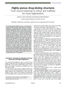
3.1. Comparison with Lee and Liu’s (1995) theory The present method is theoretically equivalent to those presented by Rojanakamthorn et al. (1989), and Losada et al. (1996), when applied to the case of one-slice and twolayer structure, with the upper layer being water. This problem may be viewed as a foundation in studying the porous breakwater, and has been discussed widely. Among those associated studies, however, few attentions have been drawn to Lee and Liu (1995), who proposed an analytical solution by uncoupling the inhomogeneous boundaryvalue problem into two homogeneous ones. In this section, the present method is compared with Lee and Liu (1995) through the prediction of the reflection coefficient K R and transmission coefficient K T , where a submerged porous rectangle with width of 2d, twice the water depth, and height of d=2, half the water depth, is considered. Hereinafter, the virtual mass coefficient is set 1.0 and N is set 15 in the present theory. The theoretical solutions in terms of K R and K T against increasing K 0 d are shown in Fig. 4, with thorough physical descriptions for porosity and
By solving the 2 ) ðM 1 þ 1ÞðN þ 1Þ linear matrix equations composed of Eqs. (23)–(26) and (32)–(33) yields the values of unknown coefficients AM 1 þ1;q , B0;q , Am;q , Bm;q , where m ¼ 1; 2; 3; . . . ; M 1 , and q ¼ 0; 1; 2; 3; . . . ; N. The reflection coefficient defined by the amplitude ratio between reflective wave and incident wave is expressed by 2o jB0;0 cos k0;0 dj, gH
2o jAM 1 þ1;0 cos k0;0 dj. gH
0.8 h1=d/2, d = ∆1/2
(36)
while the transmission coefficient defined by the amplitude ratio between transmitting wave and incident wave is KT ¼
1.0
(37)
When the porous breakwater is connected to a solid vertical wall in the rear boundary x ¼ bM 1 , i.e., no transmission area slice M 1 þ 1 appears, we should use an impermeable boundary condition at rear boundary x ¼ bM 1 ,
qfM 1 ;n ¼ 0, (38) qx instead of using Eqs. (5c) and (5d), according to which Eqs. (25)–(26) are built. Eq. (38) at the nth layer is multiplied by
KR and KT
KR ¼
(39)
3. Results and comparisons
kmþ1;q Rm;p;q
where orthogonality of the mth slice is applied. In the same manner, the pressure continuity condition Eq. (5f) in each layer is multiplied by emþ1;n a2mþ1;n Z mþ1;n;p , p ¼ 0; 1; 2; 3; . . . ; N, and integrated along !hn!1 pzp ! hn , summed together from n ¼ 1 to M 2 to give one set of linear equations
q¼0
ekM 1 ;p ðbM 1 !bM 1 !1 Þ AM 1 ;p ! BM 1 ;p ¼ 0.
q¼0
)ð!Amþ1;q þ ekmþ1;q ðbmþ1 !bm Þ Bmþ1;q Þ ¼ 0,
N X
eM 1 ;n a2M 1 ;n Z M 1 ;n;p , p ¼ 0; 1; 2; 3; . . . ; N, integrated along !hn!1 pzp ! hn , and summed from n ¼ 1 to M 2 , giving
ε1,1=1.0, f1,1=0.0 ε1,2=0.4, f1,2=1.0 present theory KR present theory KT theory(Lee and Liu,1995) KR theory(Lee and Liu,1995) KT
0.6
0.4
0.2
0.0 0.0
1.0
2.0
3.0
K0d Fig. 4. Response of waves passing a single-layer submerged porous structure.
ARTICLE IN PRESS 1696
J.-F. Lee, Y.-M. Cheng / Ocean Engineering 34 (2007) 1690–1700
friction assigned, and D1 ¼ b0 ! b1 denoting the width of the structure. An extremely high coincidence of the present method and Lee and Liu’s (1995) method is observed, suggesting the validity and correctness of our algorithmic scheme, as the basic verification. 3.2. Comparison with Lee’s (1987) study Also with the purpose to derive an analytical solution for the problem of wave-porous structure interaction, Lee (1987) considered a multi-region scheme using a different assumption from Rojanakamthorn et al. (1989) on eigenvalues, and carried out an experiment for verification. It is a relatively early work, though, we put this to compare and verify our present study in this article, mainly because Lee (1987) also divided the domain of the problem into a number of rectangles, both horizontally and vertically, in accordance to the geometry and physical composition of the porous structure, as what we do in the present derivation. In Lee’s experiment, a homogeneous porous rubblemound submergence with trapezoidal geometry is used to protect a vertical seawall behind, of which the porosity e is 0.441, intrinsic permeability K p 4:31 ) 10!5 ft2 , and dimensionless turbulence coefficient C f 0:3637, with its
5
12
5
10
5.0
2.5
2.5
unit ft 2.5
2.5
7.0
0.625 1.25 1.25 1.25 0.625 unit: ft Fig. 5. (a) Geometrical dimension of Lee’s (1987) experimental setup; (b) definition of multiple regions for the problem domain.
geometrical dimension shown in Fig. 5(a). Lee (1987) transforms the trapezoidal geometry of the breakwater into an approximated one shown in Fig. 5(b) when calculating the wave field over it by theory, and so does the present study. Figs. 6(a)–(c) show the variation of the reflection coefficient versus dimensionless water depth d=L0 , for three chosen cases of wave steepness, H=L0 ¼ 0:01, 0:015oH=L0 o0:020, and 0:04oH=L0 o0:05. The present study is using the averaging value of H=L0 in the last two cases, as the value of H=L0 is not pinpointed in Lee’s (1987) study, but only the relatively constant range is offered. The water depth is 12 ft. In addition to Lee’s (1987) experimental results, his analytical prediction is also plotted in these figures for comparison. Theories of the present study and Lee (1987) are different from each other, either in solution form or in solution approach, though, it is seen in the figures that they are matching very well with respect to predictions on the reflection coefficient K R . There appears an ignorable deviation of the experimental data comparing to both theories, however, especially for incident waves of shallower water depth. According to Lee (1987), the fact of underestimating the reflection coefficient K R in experiment may be caused by the presence of second order waves in the long wave envelope nodes observed during the experiments. Generally speaking, compared to the conditions of shallower water depth, the agreement of the two theories with experiment continues to rise when the value of H=L0 increases. Figs. 7(a)–(c) indicate the distribution of reflection coefficient K R versus wave steepness H=L0 , on the conditions of wave period given as T ¼ 2:294, 3.425, and 3:937 s, respectively. The water depth remains 12 ft. Again the comparison shows that two analytic solutions go with each other well, but they both overestimate values of K R in experiments. Possible factors that may result in the overprediction on K R for theories in comparison with experiment were explained in Lee’s (1987) study, mainly about the extra energy dissipation due to the defects of the experimental environment, which may also result from the nonlinear wave effect. Figs. 8(a)–(c) show comparisons between analytical solutions and experiment concerning the dimensionless dynamic pressure distribution within the porous structure, where the water depth d ¼ 12 ft, and wave cases of T ¼ 6:36 s with H ¼ 1:09 ft, T ¼ 3:93 s with H ¼ 1:13 ft, as well as T ¼ 2:29 s with H ¼ 1:35 ft, are picked, respectively. The dynamic pressure is non-dimensionalized, being divided by the one at the intersection of seawall and top of the porous structure. In these figures of dynamic pressure, solid line indicates the present analytical solution, meanwhile, dash line and cross represent Lee’s (1987) analytical solution and experiment, respectively, both being figured out only within the porous structure in his research. Fig. 8(a) illustrates the results for a relatively long wave with T ¼ 6:36 s, where both the theories and the experiment indicate a pressure
ARTICLE IN PRESS 1697
1.0 0.9 0.8 0.7 0.6 0.5 0.4 0.3 0.2 0.1 0.0 0.00
d=12 ft, H/L0=0.01 present theory experiment (Lee, 1987) theory (Lee, 1987)
0.04
0.08
0.12
0.16
KR
KR
J.-F. Lee, Y.-M. Cheng / Ocean Engineering 34 (2007) 1690–1700
0.20
1.0 0.9 0.8 0.7 0.6 0.5 0.4 0.3 0.2 0.1 0.0 0.04
d=12 ft, 0.015