and torques required to produce a prescribed motion in a system. ... The process to define a dynamics-based animation sequence may be divided into three ...
A Tool for Interactive Control in Dynamics-Based Animation Thomas M. Koller ETH Zürich, Switzerland Arghyro Paouri Nadia Magnenat Thalmann MIRALab, University of Geneva 24 rue du Général-Dufour CH 1211 Geneva, Switzerland Daniel Thalmann Computer Graphics Lab Swiss Federal Institute of Technology CH 1015 Lausanne, Switzerland ABSTRACT Dynatex is a program to simulate the dynamic behavior of a system of connected rigid bodies using both direct dynamics and inverse dynamics. The system is based on the use of a heterogeneous list of controls (called events), that can be edited during the simulation. Supported events include external forces, torques, wind force, various constraints, collisions, attraction. All the variables that describe the state of the body and the simulation are visible to the user upon demand and may be changed at any time. Practical examples are shown including trapeze motions.
KEYWORDS: Interactive Dynamics, Constraint, Force, Collision 1. INTRODUCTION In recent years, the use of simulation techniques [Armstrong et al. 1987; Arnaldi et al. 1989: Barzel and Barr 1988; Isaacs and Cohen 1987 and 1988; Platt and Barr 1988; Thalmann 1991; Wilhelms 1987; Witkin et al. 1987; Witkin and Kass 1988] to produce computergenerated films has become an important subject in computer animation, and many efforts have been made in this field. Although key frame animation is still most commonly used, and is much more efficient, dynamics-based techniques have the advantage of producing more realistic results. However there are many disadvantages, one is the difficulty of controlling a physically simulated body. In our work, we will describe an approach to this problem, as well as other concepts related to the physical simulation of general and human bodies. There are two kinds of dynamics-based methods: non-constraints methods and constraintbased methods. Non-constraints methods are the most popular and are based on parameter adjustment. In constraint-based methods:, the animator states in terms of constraints the properties the model is supposed to have, without needing to adjust parameters to give it those properties. In dynamic-based simulation, there are also two problems to be considered: the forward dynamics problem and the inverse-dynamics problem. The forward dynamics problem consists of finding the trajectories of some point (e.g. an end effector in an articulated figure) with regard to the forces and torques that cause the motion. The inverse-
dynamics problem is much more useful and may be stated as follows: determine the forces and torques required to produce a prescribed motion in a system. This paper describes Dynatex. a program to simulate the dynamic behavior of a system of connected rigid bodies using both direct dynamics and inverse dynamics. The system is based on the use of a heterogeneous list of controls (called events), that can be edited during the simulation. Supported events include external forces, torques, wind force, various constraints, collisions, attraction. All the variables that describe the state of the body and the simulation are visible to the user upon demand and may be changed at any time. Practical examples are shown including trapeze motions.
2. DESCRIPTION OF THE DYNATEX SYSTEM 2.1. Purpose of the system In Dynatex, the basic simulation algorithm uses direct dynamics, but the constraints (collisions, spatial constraints etc.) are solved by inverse dynamics. In order to make the simulations more realistic, the concept of friction has been also introduced. Only one kind of friction is taken into account: the friction due to the resistance to rotation at the joints. Friction due to air is ignored. The process to define a dynamics-based animation sequence may be divided into three steps: 1. edition of dynamic data concerning limbs or members 2. edition of events 3. simulation 2.2. Edition of limbs This first step consists in building articulated bodies and to specify dynamic data. Data concerning a selected limb may be interactively changed. • the mass of the limb may be modified • the mass center is initialized at the geometric center, but it could be changed if necessary • the limb length and radius may be also edited There are also specific data for the joints: • a friction factor may be entered; it is applied to each rotation axis and corresponds to an energy loss • joint angles may be modified to change the limb orientation • angle limits for the current joint relative to each rotation axis • relative and absolute positions Direct numerical input should be used when the simulation is very sensitive about small changes in the parameters. Otherwise a graphics editor DynaEdit allows interactive rotation and translations of the limbs.
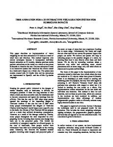
2.3. Definition and edition of events Controls should be introduced to define motions to be applied to the articulated bodies. These controls consist of constraint activations that we call events. The following events are supported in the Dynatex system: 1. An external force may be specified by its amplitude and direction; it acts at the indicated position of the link. 2. An external torque may be specified by its amplitude and direction; it acts between the cureent link and its father link. 3. A simulated wind force may be given by its direction and amplitude A; the wind force is calculated as F = A cos α where α is the angle between the link and the wind direction. 4. The nail constraint fix a point on a link to a point in space. I first generates the forces to get the link to the desired point and then the forces to keep it there. 5. The direction constraint produces torques on a link to get a specified direction and then produce the torques to keep it there 6. A new father link may be specified as a connection event that generates forces to bring the link to the right position and it is connected to its father link. 7. Collisions against walls can be specified and the link will then be tested if it hits them. In this case, forces are generated that depends on the elasticity and friction of the wall. Object collisions may be also specified in the same way. 8. A link can be connected to a point using a spring that is described with its elasticity constant k and a natural length. If the spring is stretched it will produce the force given by Hook's law. 9. A link may be disconnected from its father link and pushed away from it with the specified force. 10. Two kinds of attraction (or repulsion) forces may be specified: attraction to (or repulsion from) a specified point in space and attraction (or repulsion) between two links. The dynamic simulator computes the complete simulation according to user parameters such as time range simulation, gravity and display options. 2.4. Interactive control One problem is when the interaction should take place. We have the option of interacting with the system while it is running or to predefine the controls before, let the simulation run and make correction if we are not satisfied with the result. We believe that interactive control is the main point. Only during the simulation the animator knows the positions and parameters of the body and can fit the controls to the current situation. We therefore propose the use of a heterogeneous list of controls (we call them events), that can be edited during the simulation, but can also be saved and replayed. If a complex motion has to be specified, first the events are created that produce an idea of the movement, then the simulation can be repeated and the animator can specify new events that refine the motion. All the information about the motion can be found in a concise way in an event list. 3. ARCHITECTURE OF THE DYNATEX SYSTEM 3.1. System design The program has been developed for the Silicon Graphics IRIS 4D workstations using the C programming language. It runs on all machines with at least 8 Megabytes, the minimal configuration of the Personal IRIS workstation. The program is physically and logically divided into several modules, each of which handles and implements a certain task as shown
in Fig.1. The modules themselves are divided into different files that, where possible, implement the model, view and control parts according to the standard MVC-model. Body
Simulation Frame List
Window
Event List
Model
Model
Model
Model
Model
View
View
View
View
View
Control
Control
Control
Control
Control
Dynamic Simulation (Main Form)
Edit Body and Members
Control Simulation and Frames
Edit Simulation and View Parameters
Edit Event List
Events Different Event Types
Add new Events
Interface Fig.1 Modules of the program and their connections to the interface
The simulation method used is the Armstrong method. Collision detection is based on the Cohen-Sutherland clipping algorithm applied to the planes x-y then to the plane x-z. Our main point was put on interactivity. All the variables that describe the state of the body and the simulation, should be visible to the user upon demand and he should be able to change them at any time. It is not enough to have only a visual feedback of the simulation: numerical values are needed for the control of the simulation. We should also be able to specify the control at the moment it is used. 3.2. Event list The event list is the part of the interface that allows the user to control the body during the simulation. As we have seen previously, it is necessary to have a flexible, easy extensible mechanism. For this purpose, we use a heterogeneous list of events of different types. A structured type EVENT declares the shared data of all event types and procedure variables that are used for the messages. An info field in the structure points to the special data used by the individual event types. The event themselves are organized in a sorted event list. Since we need fast access to events of a special member and do not want to search through the main list every time to find the first event of a certain member, we support also a list for each member. Its first elements can be accessed directly. This event structure facilitates the implementation of new events. Nothing in the interface has to be altered. The current event types that are supported corresponds to the events described in Section 2.3. Fig.2-7 shows sequences involving actors on trapeze. The actors and trapezes are modeled very simple to have a fast response time to the system. For the parameters and models used, several frames could be computed and displayed per second. The control was done using the whole variety of the available events: forces, torques, disconnections, nail constraints, connection constraints. The tree structure of the body had to be changed between frames, as the father link of the jumping actor also changed. A new event was implemented for this purpose that connects a link to a new father link. A short computer-generated film has been produced showing a more complex trapeze sequence with a more realistic virtual human. Unfortunately at the end of the film, the character falls on the floor. The virtual human was
created with our sculpting software based on the Ball and Mouse metaphor [LeBlanc et al. 1991]. The trapeze motion has been generated using Dynatex; the human position has been obtained using inverse kinematics from the trace of the trapeze. Human motion has been adjusted using keyframing. The camera animation has been produced using the program ANIMATOR with 3D interactive input based on the SpaceBall. The scenes was rendered using Rayshade 3.0. The complete production process is shown in Fig.8. Fig. 9 shows an image with complex deformable clothes also animated using a physics-based model [Carignan et al. 1992]. SCULPTING PROGRAM
DYNATEX
Edit member
Edit Events
Simulation
trace file
BODY ANIMATION PROGRAM
description file
inverse kinematics
key frames
RAYSHADE
ANIMATOR
Fig.8. The Production process of a trapeze sequence 4. ACKNOWLEDGEMENTS A first version of the system has been implemented by Rejean Gagné from the University of Montreal. The research was partly supported by "le Fonds National Suisse pour la Recherche Scientifique", Natural Sciences and Engineering Council of Canada and the FCAR foundation. 5. REFERENCES Armstrong WW, Green M, Lake R (1987) Near Real-Time Control of Human Figure Models, IEEE Computer Graphics and Applications, Vol. 7, No 6, pp.28-38. Arnaldi B, Dumont G, Hégron G, Magnenat-Thalmann N, Thalmann D (1989) Animation Control with Dynamics, in: Magnenat-Thalmann N, Thalmann D (eds) State-of-the-Art in Computer Animation, Springer, Tokyo, pp.113-124. Barzel R, Barr AH (1988) A Modeling System Based on Dynamic Constraints, Proc. SIGGRAPH '88, Computer Graphics, Vol. 22, No4, pp.179-188. Carignan M, Yang Y, Magnenat Thalmann N, Thalmann D (1992) Dressing Animated Synthetic Actors with Complex Deformable Clothes, Proc. SIGGRAPH '92, Computer Graphics, Vol. 26, No4,.
Isaacs PM, Cohen MF (1987) Controlling Dynamic Simulation with Kinematic Constraints, Behavior Functions and Inverse Dynamics, Proc. SIGGRAPH'87, Computer Graphics, Vol. 21, No4, pp.215-224. Isaacs PM, Cohen MF (1988) Mixed Methods for Complex Kinematic Constraints in Dynamic Figure Animation, The Visual Computer, Vol. 4, No6, pp.296-305. LeBlanc A, Kalra P, Magnenat-Thalmann N and Thalmann D (1991), Sculpting with the "Ball & Mouse" Metaphor, Proc. Graphics Interface '91, Calgary, Canada, pp. 152-159. Platt JC, Barr AH (1988) Constraint Method for Flexible Models, Proc. SIGGRAPH '88, Computer Graphics , Vol. 22, No4 , pp.279-288. Thalmann D (1991) Dynamic Simulation as a Tool for Three-Dimensional Animation, In: New Trends in Animation and Visualization, John Wiley and Sons, pp.257-272. Wilhelms J (1987) Using Dynamic Analysis for Realistic Animation of Articulated Bodies, IEEE Computer Graphics and Applications, Vol. 7, No 6, pp.12-27 Witkin A, Fleischer K, Barr AH (1987) Energy Constraints on Parameterized Models, Proc. SIGGRAPH '87, Computer Graphics, Vol.21, No4 , pp.225-232. Witkin A, Kass M (1988) Spacetime Constraints, Proc. SIGGRAPH '88, Computer Graphics, Vol.22, No4 , pp.159-168.