TREE ANIMATION FOR A 3D INTERACTIVE VISUALIZATION SYSTEM FOR HURRICANE IMPACTS Peter A. Singh1, Na Zhao1, Shu-Ching Chen1, Keqi Zhang2 1
Distributed Multimedia Information System Laboratory, School of Computer Science Florida International University, Miami, FL 33199, USA 2 International Hurricane Research Center, Florida International University, Miami, FL 33199, USA 1 {psing002, nzhao002, chens}@cs.fiu.edu,
[email protected] ABSTRACT This paper describes an implementation of vertex weighting for real-time animation of 3D trees as a result of wind force and direction. This method improves over similar techniques because it incorporates individual branch animation on 3D models, whereas previous works perform animations on the model as a whole or use planar billboards to visualize the tree. Our tree animation is used in an interactive system that visualizes the effects caused by a hurricane’s impact on a virtual city. The system uses models created with 3D Studio Max and the animations are implemented in OpenGL and the nVidia Cg shader language. 1. INTRODUCTION Keeping the general public informed to the dangers of natural disasters, such as hurricanes, is difficult for emergency planners. If there are long stretches of time where a hurricane does not strike land, the inhabitants tend to become complacent and ignore the warnings from the officials. This was the case in 1992 when many people ignored the warnings of the impending danger of Hurricane Andrew. It was also the case in 2004 when many people misinterpreted the dangers of Hurricane Charley, believing that it would impact only a specific area to the north, the citizens of Port Charlotte did not prepare and as a result they suffered devastating consequences. However, as a result of the damage caused by Charley, many people throughout the state responded by overpreparing for the following three storms even though they were not in the projected paths. This limited the availability of emergency supplies for affected people. In the case of hurricanes, most people receive their information from their local meteorologist on the evening news. Generally, this involves the standard weather graphics involving radar imagery and projected paths of
the storm or maps of areas that may experience flooding due to storm surge. Unfortunately, the charts and maps that are often used do not convey the personal impact that people can suffer. We believe our system will help in educating people to the possible dangers of a storm, by showing them how it may directly affect them and their homes. We do this by recreating locations where a hurricane may strike and animating storm related phenomena such as storm surge, rain, and wind effects on objects such as plants and buildings. The focus of this paper is the implementation of tree animation related to hurricane force winds where the trees are modeled as 3D objects rather than planar billboards. There is an abundance of work related to creating and rendering plant life [2][4][5], but very little with regard to animating it. Jeff Thelen’s “Blustery Trees” demo [8] performs tree animation with respect to wind, but it is limited to bending the tree model as a whole. Our implementation creates animations for the tree trunk and individual tree branches. This method is ideal for soft branches, such as those on palm trees, which are common in the locations we have modeled. In addition, our implementation also takes advantage of modern programmable graphics cards to efficiently animate many highly detailed models in real-time. This paper is organized as follows. Section 2 discusses the techniques used in our proposed model for tree animation. This includes the vertex weighting technique, lighting technique, the programmable graphics pipeline, and how they are applied in our tree animation model. The conclusion is given in Section 3. 2. TREE ANIMATION In earlier versions of our system, we have implemented vegetation animation using planar billboard models of trees [1]. Planar billboards are simple to implement and consume very little computing resources, but they do not
provide realistic models at close ranges. The lack of details in the model only allows us to perform simple rotation operations to pivot the tree trunk or branches at their base. However, billboard models are preferable at distances further away from the camera, where the lack of details is not so readily noticeable to the user. Our objective is to animate the bending and swaying of trees, yet save the computing power by using models with varying levels of details. Less detailed models, including planar billboards, will be displayed further away from the viewing camera.
Q2, Q3, & Q4). If the wind comes from a different angle, say 210º, then the quadrants can be rotated 30º counterclockwise to be positioned properly. Or, if the wind comes from 150º, then the quadrants would be rotated 30º clockwise.
2.1. Vertex Weighting Our solution to bending the 3D tree models is using a technique known as Vertex Weighting or Vertex Skinning. It was developed to animate human skin around joints such as elbows and knees [6]. Using traditional animation of rigid bodies, sharp seams and gaps would appear when animating joints. Vertex Weighting provides a smooth bending around these areas by having each point on the skin reacts to the underlying bone structure. When a set of bones pivot at a joint, the vertices on the surface react accordingly depending on the influence each bone exerts on them. The new position of a vertex is calculated by taking this influence into account by assigning each bone a weight value. Equation 1 shows how the new vertex position, v’, is calculated. Mi is the transformation matrix that represents the ith bone. Our implementation only uses rotation transformations about the z-axis, which points in the “up direction” for our scene. wi is the weight value assigned to the ith bone, c is number of bones, and v is the original vertex position. The linear weighting method is used when assigning values to the individual bone weights. This means that the sum of all weights used should equal one. Values other than one can be used, but they result in shearing or twisting effects. v′ =
c i
wi M i v with
c
wi = 1
i
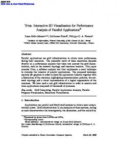
Equation 1. Calculating the new vertex position [7] 2.2. Applying Vertex Weighting to the Model To apply Vertex Weighting technique to our tree model, we simulate three interconnected bones for the tree trunk and each branch. The bones are laid out in a similar fashion to that of a human arm, with an upper arm, forearm, and wrist. We then take into account the direction of the wind with respect the angle of the branch to determine how each branch will bend. As shown in Figure 1, if we assume that the wind is coming from the west (180º), each branch will fall into one of 4 quadrants (Q1,
Figure 1. Branch angles separated into quadrants The next step is to calculate what angle, with respect to the wind direction, that each branch will bend to if it were to bend at its maximum angle. This maximum angle is arbitrarily defined, so that the resulting animation is visually pleasing. In our case, if a branch were pointing directly into the wind, for example having an angle of 180º (Q3) with the wind also coming from that direction (flowing towards 0º), then the branch will bend forward 120º so that its new angle is 300º. This is only in the extreme case, generally branches falling in Q1 and Q4 will have new angles in the range of ±[0, α2], and those falling in Q2 and Q3 will have new angles in the range of ±[α2, (α2+α1)] as shown in the shaded region of Figure 1. The values of α1 and α2 depend on how much we want the branches to bend. In our case, α1=10º and α2=20º. Larger values may be used for sturdier trees so that α1+α2≤180º. BA′′ = Wind Direction − BranchAngle Q1 : BA′ =
BA′′ × 20 90
Q3 : BA′ =
BA′′ − 270 × 10 90
+ 20
Q 2 : BA′ =
BA′′ − 90 × 10 90
+ 20
Q 4 : BA′ =
BA′′ − 360 90
× 20
Equation 2. Calculating the branch angle B1 = ROTZ − BA′ +
BA′ 7
B2 = ROTZ (− BA′) B3 = ROTZ − BA′ +
BA′ 7
w1 =
1 − 2x / L 0 1
w2 = 1 − w1 w3 =
x≤L
x>L x = L/2 x≤L
x>L 1 − w3 1 − 2x / L x ≤ L 0
x>L
Equation 3. Bone transformation formulas
To apply these concepts to the tree model, we present Equations 2 and 3. Equation 2 lists a set of equations that are used to calculate the new branch angles based on which quadrant the branch is in. We then use these angles in Equation 3 to calculate the three bone transformation matrices per branch. ROTZ signifies that each Bi is a rotation matrix about the z-axis. wi is the weight value for ith bone, which is dependent on the position of the vertex, x, along the branch length L. Our models are created in the 3DS format in 3D Studio Max. Each branch contains information embedded within the model of its length (L) and the angle ( ) that it is attached to the trunk with respect to the XY-plane as shown in Figure 2. Also shown in this figure is the same branch with vertex weighting applied to it as a result of the wind coming from two different angles.
Figure 2. Branch bending due to wind direction
Figure 3. Tree bending with different LOD models By applying rotation transformations to the trunk and branches of a Royal Palm tree model, we can bend them to varying degrees simulating the effects of high winds. A great advantage of using this technique is that it is not limited to 3D models. It may also be applied to planarbillboards as long as there are enough polygons to bend. This allows us to create multiple models of the same tree, but with varying levels of details (LOD). Figure 3 shows this application to the 3D model of a Royal Palm tree. The first image is the model with no bending applied. The second and third images are wire-frame versions of the tree with different levels of details. The tree in the middle contains over 30,000 polygons. The tree on the right contains approximately 1,500 polygons.
2.3. Programmable Graphics Pipeline One of our main goals is to implement a system that performs in real-time on a single consumer level computer, so we must always search for ways to reduce the workload on the CPU. Unfortunately, the vertex weighting method is computationally expensive. Fortunately, we can alleviate this problem because many modern consumer graphics cards now come equipped with a programmable graphics pipeline. This allows a developer to take advantages of hardware implementations of common 3D graphics operations. Figure 4 depicts the graphics pipeline of a modern GPU. The top four components are the standard graphics pipeline while those two components on the bottom of Figure 4 are the programmable parts of the pipeline consisting of the vertex and fragment processors. A programmer can take advantages of the vertex and fragment processors by writing vertex and pixel shaders. However, when doing so, certain sections of the standard pipeline are bypassed. We implemented the Vertex Weighting method as a vertex shader with the nVidia Cg language [9]. Cg is a C-like language specially designed for vertex shaders. Integrating a Cg shader with our system is seamless because nVidia provides a runtime environment that allows them to be integrated into C++ and OpenGL [10] programs, where our system is developed.
Figure 4. Programmable graphics pipeline [3] 2.4. Lighting One aspect of using the programmable pipeline is that the programmer must perform the operations that are bypassed in the standard pipeline. This includes lighting operations that give the objects their 3-dimensional appearance. The lighting model that we use to perform these operations is the diffuse lighting model. Each vertex in a model has an associated material property for ambient (MatAmbient), diffuse (MatDiffuse), and specular light (MatSpecular). A set of material coefficients, d and s for the diffuse and specular components respectively, are calculated using the Light (L), Normal (n’), Half (H), and View (V) vectors. These coefficients are then multiplied with the material properties and a final color (ColorFinal) is computed, as
shown in Equation 4. The equation for n’ is related to Equation 1 for calculating the new vertex position. Figure 5 depicts the vectors used in the lighting calculation, and Figure 6 depicts the tree animation with and without diffuse lighting applied to it. n′ =
c i
T
wi M i−1 n with
c
wi = 1
i
ColorFinal = Mat Ambient + (MatDiffuse × d ) + (MatSpecular × s )
d = L • n′
s = (H • V )
2
Equation 4. Calculating the normal [7] and color [3]
produce realistic animations on a single workstation level computer. This system’s intended application domain is as an educational tool for the citizens who live in hurricane affected areas. Visualizing possible damage effects by a storm in an affected area will allow people to make better informed decisions as to whether they should evacuate or not. Tree animation is a component of ambient details that adds to the overall experience of the virtual environment. 4. ACKNOWLEDGEMENT This research project was supported in part by a grant from the National Oceanic and Atmospheric Administration (NOAA). 5. REFERENCES [1] S.-C. Chen, K. Zhang, and M. Chen, “A Real-Time 3D Animation Environment for Storm Surge,” In Proceedings of the IEEE International Conference on Multimedia & Expo (ICME 2003), Baltimore, MD, USA, July 6-9 2003, pp. 705708.
Figure 5. Calculating diffuse lighting [3]
[2] O. Deussen, C. Colditz, M. Stamminger, and G. Drettakis, “Interactive Visualization of Complex Plant Ecosystems,” In Proceedings of IEEE Visualization 2002, Boston, MA, USA, October 27-November 1, 2002, pp. 219-226. [3] R. Fernando, M.J. Kilgard, The Cg Tutorial: The Definitive Guide to Programmable Real-Time Graphics, AddisonWesley, Boston, MA, USA, February 2003. [4] M. Fuhrer, H. W. Jensen, and P. Prusinkiewicz, “Modeling Hairy Plants,” In Proceedings of Pacific Graphics 2004, Seoul, Korea, October 6-8, 2004, pp. 217-226. [5] P. Prezemyslaw, A. Lindenmayer, The Algorithmic Beauty of Plants, Springer-Verlag, New York, NY, USA, April 1996.
Figure 6. Tree model with no lighting (left) and with diffuse lighting applied (right) 3. CONCLUSION In this paper, we described a method to implement 3D tree animation using the vertex weighting technique. Our implementation, in addition to performing trunk animation in a similar fashion to the “Blustery Trees” demo [8], also performs animation for the individual tree branches. The animation is implemented in OpenGL and the nVidia Cg language. With the Cg language, we have taken advantages of the programmable graphics pipeline available in modern graphics cards. This takes the computationally intensive operations performed in vertex weighting from the CPU to the GPU, allowing us to
[6] R. Woodland, “Filling the Gaps: Advanced Animation Using Stitching and Skinning,” Game Programming Gems, Edited by M. DeLoura, Charles River Media, Rockland, MA, USA, September 2000, pp. 480-483. [7] S. Domine, “Mesh Skinning,” http://developer.nvidia.com/object/skinning.html [8] J. Thelen, “Blustery Trees,” http://edgarapoe.home.mindspring.com/quixotic/blustery_tre es.htm [9] NVIDIA Cg Toolkit, http://developer.nvidia.com/cg [10] OpenGL, http://www.opengl.org