nomic or Organic Manager) models in its observer part (Monitor, Anal- yse; MA- -) the ... server service monitors the progress of a real-time application thread. If.
A Two-Layered Management Architecture for Building Adaptive Real-time Systems Florian Kluge, Sascha Uhrig, J¨org Mische, and Theo Ungerer Department of Computer Science - University of Augsburg 86159 Augsburg, Germany {kluge, uhrig, mische, ungerer}@informatik.uni-augsburg.de
Abstract. The concepts of Autonomic and Organic Computing (AC/OC) promise to make modern computer systems more secure and easier to manage. In this paper, we extend the observer/controller architecture typically used in AC/OC systems towards a new target area – embedded real-time systems. As a result we present a two-layered management architecture. We discuss aspects of internal communication and design a communication model. Finally, we present a generic classification system for the upper layer of the management architecture.
1
Introduction
Academic and industrial research investigate concepts to master the growing complexity of today’s computer systems. In 2001, IBM introduced the concept of Autonomic Computing (AC) [1] for the management of growing IT infrastructures with focus on the so-called Self-X properties of Self-Configuring, Self-Healing, Self-Optimising, and Self-Protecting. In 2003, Kephart and Chess presented an architecture for the design of such self-X systems [2]. A productive system is embedded into a loop of Monitor, Analyse, Plan, and Execute. The different stages of this MAPE cycle have access to a common knowledge base. The MAPE cycle optimises the operations of the underlying productive system with respect to the self-X properties. M¨ uller-Schloer introduced the concept of Organic Computing (OC) in 2004 [3] to convey the ideas of Autonomic Computing into the field of embedded computing devices. Richter et al. developed a generic observer/controller architecture for the design of OC systems [4]. Here, similar to the MAPE architecture, the production system is embedded into the control loop of observation and control which aims to improve the system’s operation. Both the MAPE cycle as well as the observer/controller architecture can be equipped with functionalities for the learning resp. prediction of behaviour. Both concepts have the following features in common: Based on monitoring of relevant system parameters, the management unit (called Autonomic or Organic Manager) models in its observer part (Monitor, Analyse; MA- -) the current system state. The monitored data is aggregated with previous state information and analysed. Future trends may be predicted. The controller part (Plan, Execute; - -PE) plans new actions
and triggers their execution on the System under Observation/Control (SuOC), i.e. the productive system. These architecure models are designed very generic and do not take the particular requirements of embedded hard real-time systems into account. Within the German Science Foundation (DFG) priority program Organic Computing, there are some projects dealing with real-time or embedded systems. The project DoDOrg [5] investigates a digital organism for realtime applications. It aims at the use of reconfigurable hardware to implement virtual organs that can handle specific tasks. In the EPOC project [6], methods of performance analysis and optimisation are developed. The ASoC project aims at the development of an architecure and design methodology to embed autonomic and organic computing principles into a System-on-Chip [7]. However, neither of these projects does address the fundamental concepts of software architectures for embedded realtime systems in depth. Solomon et al. presented a reference architecture for autonomic real-time systems [8], but did not incorporate the resource constraints of embedded systems. The contribution of this paper is an analysis of applying the concepts of Autonomic and Organic Computing to embedded real-time systems. It is based on the observation that the extensive analysis and the planning part are not feasible for real-time applications. Therefore a new two-layered reaction system inspired by the natural reflex system is proposed. An extensive analysis of communication concepts leads to a detailed communication model between the two layers. On base of this communication model and on further requirements from real-time systems we developed a classification system for the derivation of reactions responding to harmful states of the managed system. In section 2 we present the two-layered management architecture. Section 3 gives a detailed discussion of communication between the two layers, and in section 4 we present DCERT, a concept for Dynamic Classification in Embedded Real-Time systems. Section 5 concludes this paper.
2
The Two-Layered Management Architecture
In the targeted environment of embedded systems we have to heed several constraints originating in hardware restrictions and application requirements. Hard real-time applications must never miss a deadline. So it is necessary to guarantee that an AC/OC management does not influence the timing behaviour of such an application in any unpredictable way. The microcontrollers and the software usually are built to fit, so that no money is wasted on unused performance. Simultaneously, the AC/OC management should support the real-time operation of such systems and therefore provide fast reactions with a fixed timing overhead that has a low upper bound in terms of execution cycles. An embedded system usually comprises a vast range of parameters relevant for system monitoring. Also, there are many points where decisions of the management can be applied to. However, the interpretation of all monitored parameters would be very expensive. Also, in most cases it is possible to find a reasonable solution when regarding only a small subset
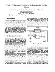
of all parameters. There might be better solutions, when taking a larger set of parameters into account, however due to planning or learning algorithms this would happen at the cost of a higher reaction time possibly without any upper timing bound. The following example will clarify this idea. As initial situation, a observer service monitors the progress of a real-time application thread. If the application impends to miss its deadline, several countermeasures are possible. The easiest solution would be to increase the processing time of the application, if possible. This solution only needs to monitor two parameters: the knowledge of the application’s progress and the possibility to increase the processing time. Also there is just one parameter affected, the processing time of the thread. A further solution is to increase the clock frequency, which however affects the power consumption. Finally, the monitoring information of several embedded control units (ECUs) can be brought together. Then it can be decided to move the application to a higher-performance ECU or one with more free processing time. However, the latter two solutions, especially the last one, need to evaluate much more data. Therefore, we introduce two levels of decision making (see fig. 1). On the lower level, small management units (Module Managers) are attached to distinct hardware or software modules. These module managers only work on a very small parameter set and hence, they comprise just a small and static rule set. Thus, they can reach a decision very fast within an upper bounded timing budget. These module managers correspond to the reflexes in nature.
Analyse
Global Management
Module Management
Monitor
Knowledge
A M
P
A K
Power Supply
Plan
M
K
...
Execute
A E M
P
A K
...
E M
K
E
Thread
Fig. 1. The two-layered management architecture
If a module manager has performed its reaction or cannot find a solution for a specific state, it conducts a pre-interpretation of the monitored data. This abstracted information is forwarded to the Global Manager. The pre-interpretation transforms the monitored data into a domain common
to all module managers. Thus, the global manager and the algorithms it comprises can be designed in a generic way. Furthermore, the module managers place their actions to the global manager’s disposal. The global manager merges the abstract monitoring information of all module managers. It takes over, if a global view of all modules is required to react to some failure state. For decision making, several techniques are possible. This could be some kind of classifier system or generic rules, but also a planner to deduce complex operation sequences. Using these techniques, the global manager infers necessary actions from the current monitoring data. These actions are executed within the module managers that provided them. The module managers need not implement the complete MAPE cycle. As figure 1 shows, several parts can be left out. If only the Planning part is missing (MA-E), the the monitoring information is always forwarded to the global manager for decision making. Sometimes, it may be also sensible to build pure monitors, although these must always be accompanied by an analysis component for the data abstraction (MA- -). An example for such a module would be the monitoring of a battery. Apparently, there are no actions that can be executed directly on the battery. It is even possible to define a pure actor module (- - -E). However, the developer has to be very careful in this case, as most action have some kind of preconditions in their related module that must be met for their execution. The partition of the AC/OC Management into two layers has several advantages. Another approach would be to develop application-specific AC/OC Managers, which are based on a broad parameter set. However, this would decrease their reusability and increase development costs, because for each new application with a different parameter set a new set of managers would have to be developed. The proposed small module managers are bound to a distinct hard- or software module, instead to a specific application. They can be reused in several similar applications, thus saving development costs. Using complex managers based on a broad parameter set inevitable leads to complex decision processes in the manager. This aggravates the timing analysis of an application using such managers. Small managers will bring less overhead into the application, so the timing behaviour will not be influenced that much and will be easier to analyse. The solution of complex problems in the global manager is done by a generic rule system. Specificity for an application results from the combination of module managers and from the developer-defined system strategies. The derivation process itself is not influenced by the nature of its application.
3 Communication between the Two Management Layers 3.1
Information Flows
Within the two-layered management architecture, we have to regard two information flows. On the one hand, the module managers provide sta-
tus messages to the global management within a single node. These status messages represent the current parameter values monitored by the module managers. The values are mapped to a common domain, to keep the communication interface between the two layers lean. Also, the global manager is able to compare the status messages regardless of their origin. On the other hand, the global management notifies the module managers about its decisions. Thus, the execution of appropriate reactions is triggered.
Synchrony Synchrony in the communication between the two management layers concerns the question how far the appearance of status messages triggers the derivation of reactions. There is no point in triggering a decision for each single status message that is received by the global management. This would only lift the work of the module managers up to the global level. Instead, the global management must accumulate the status messages of several module managers for some time before devising a reaction. Only this way the reaction would be based on a real global view. Hence, the process of decision making should run rather asynchronously to the module-global communication.
3.2
Types of Monitors and Actors
For the design of a communication model it is necessary to take a look at the ways monitors and actors can be implemented.
Monitors Runtime information, i.e. status messages, can be generated in the following ways: – Instrumentation: The monitored application’s code is instrumented with small code blocks that generate status messages. Thus, the module manager is integrated directly into the application code. – Monitoring Service: The module manager runs as a service independently of the real applications. If at one point it cannot cope with the parameter values it is responsible for, it raises an event. – Explicitly: The module manager generates the status message on explicit enquiry of the global manager. Each of these approaches has its own problem domain, where it fits best. Application instrumentation could be used to monitor and evaluate the application’s runtime behaviour at predefined points. To monitor a battery continuously, it is possible to use a observer service running independently, e.g. at a low priority or as a timer-driven interrupt service routine. Simple status requests for a processor’s current clock frequency would be done directly by explicit requests from the global manager. As these examples show, in a final system most likely all three of these monitoring concepts will be used. Thus, they must all be taken into account by the design of the global management and the communication interface.
Actors System design must also distinguish at what place the derived reactions are executed. Clearly, the execution is the duty of the module managers’ actors, however following the above concepts there are several ways to implement an actor: – Within the application: This approach raises two problems. First, there needs to be some way of synchronisation between the application and the global management. Second, the reaction will influence the timing behaviour of the application and thus must be developed very carefully. – Separate service: The influences on the timing behaviour of the application as well as the global management are minimal in this case. However, there is again the problem of synchronisation between the global management and the reaction service. – Part of the global management: Here, no synchronisation problems occur, but the actor may delay the global management in its operation in an unpredictable way. Like the generation of status messages, all of these ways have their own domain where they perform best. So the design decisions for the actor should be based mostly on the complexity of the actor’s task. 3.3
Communication Model
Based on the preceding discussion of communication parameters, we are now able to propose a basic model for the communication between the module managers and the global management.
Collection of Status Messages Basically two concepts exist that can be applied to the communication between the two layers, the Observer Pattern and Polling. Both have their dis-/advantages for use in system monitoring. Through the observer pattern, communication is minimised. However, it stays unclear, when the global management should derive a reaction. As mentioned it is not sensible to trigger a decision for each single status message. On the other hand, using periodic polling, the decision process would start just after all messages are collected. But also in this case there are problems. The communication between the two layers is very high, as each module is questioned regularly. The whole process of message collection and possible decision making is gone through even if there is no real necessity due to a sound system state. On this account, we propose a hybrid solution consisting of two modes. GM async Only the global manager’s monitoring service is active. The module managers notify the global manager about critical states. These status messages are accumulated. If a predefined critical limit is reached, the whole management is switched into mode GM sync. GM sync Now the global management starts actively collecting status messages from all modules. Based on these data, it goes through the decision process. After the execution of the derived reactions, the system falls back into mode GM async.
Using this model, the global management is only executed if it is really necessary. Simultaneously we ensure that it works on a complete global view of the system without the overhead of periodic polling. The definition of the critical limit for the activation of the the global management presents a degree of freedom to the developer. It is not necessary that each module manager can publish messages to the communication layer in mode GM async.
Reaction Reactions always should be executed synchronously to the decision process. Apparently, the global manager should play the active part and notify the affected actors about its decision. Thus, most of the reactions will be executed through the global manager. Actors that run as separate services or integrated into an application have to provide a broker actor that is notified in their place. This broker will activate the reaction service, or set a flag for the application-integrated actor.
4
Decision-Making of the Global Management
This section describes a concept for Dynamic Classification in Embedded Real-Time systems (DCERT). Its basic ideas relate to the fields of Learning Classifier Systems (LCS) [9] and automated planning [10, 11]. Both concepts have in common that their algorithmic implementation is independent of the problem domain they are applied to, i.e. they present generic concepts. In LCS, for an input state a reaction is derived using a dynamic rule set. A learning function, usually coupled with a genetic algorithm, modifies and improves the rule set over time. The rules are usually based on a combination of true/false/don’t care-values. This allows an easy choice of rules matching the input state. Each classification cycle usually brings the system one step further towards its target state. However, during the advancement of the rule set by the genetic algorithm it is possible for disadvantageous rules to arise. Although these might be removed later by the learning function, in our problem domain they must not occur at all. The basic target of automated planning is to derive a series of actions that will bring the system from a given start state into a predefined end state. Bad states are completely avoided. Although, the planning process itself is very complex and can consume lots of processing time. This is not applicable in the domain of real-time systems, which are usually embedded computers with limited performance. In the design of the DCERT system, we unite the advantages of these two concepts, but simultaneously avoid their worst disadvantages.
4.1
Monitors - Status Messages
The module managers respectively their monitoring parts have access to the raw values of their associated parameters. For communication with the global management, these raw values are mapped into an abstract threefold metric.
Definition 1 (Status Parameters and Messages). σ denotes a monitored system parameter. Its raw value is mapped into the characteristics σ + , σ − (extreme states), σ 0 , and in special cases σ ± . The set of all monitored parameter is denoted as Σ = {σ1 , σ2 , . . . , σn }. σ itself represents a monitored systems parameter. Its characteristics σ + , σ − can represent extreme states like “energy level high/low” or the possibilities for actions, like “clock frequency can be in-/decreased”. In the latter case, also the σ ± characteristic can be used to denote the possibility for increment and decrement. The σ 0 characteristic represents a balanced state. The state messages can be furnished with a semantic meaning denoting preferred and undesired states. Definition 2 (Status Semantics). Σ+ resp. Σ− denote the sets of preferred resp. undesired states. If σk+ ∈ Σ+ , then σk− ∈ Σ− . A semantic rating is not required for every σk ∈ Σ. States contained in the semantic set usually represent states that have important influence on the operation of the whole system. States not contained in the semantic set only have marginal influence on the operation, or none at all. However, they may be preconditions for some reactions and thus are necessary to be monitored. An order extends the semantic set: Definition 3 (State Order). The state order is a total order ≤ on the semantic sets with the following properties: – σk− ≤ 0 ∀σk− ∈ Σ− ; 0 ≤ σk+ ∀σk+ ∈ Σ+ – σix ≤ σkz ⇔ σi−x ≥ σk−z , (x 6= 0, z 6= 0, i 6= k) The latter status semantics and state order are user-defined. They provide a way for the developer to influence the behaviour of the system and can be altered at runtime. The choice of Σ and the relation of the σk to specific system parameters depends on the application. The semantic set of states provides a canonical trigger for mode change of the Global Manager from GM async to GM sync (cf. 3.3), because these states have per definitionem heavy influence on the proper operation of the system. However, the user may define another boundary state as trigger. The basic design of the state messages allows an efficient implementation by means of bit sets. The order of the states can be represented by a state’s position in a bit string. For the selection of actors, we need to equip the states from the semantic set with weights. Therefore, we state the following requirements: Definition 4 (State Weights). A weight wσ+ for a semantic state σ+ ∈ Σ+ has the following properties: – wσ− = −wσ+ , and – σ, τ : σ + ≤ τ + ⇔ wσ+ ≤ wτ + Which values are assigned to these weights again lies in the responsibility of the developer.
Example 1. Monitored Parameters States Description E + /E 0 /E − energy consumption high/normal/low B + /B 0 /B − battery power high/acceptable/low T + /T 0 /T − timing behaviour of an application thread (soft realtime) frequently free time until deadline/timing behaviour ok/frequently deadline misses F + /F 0 /F − clock frequency can be increased / in-/decreased order 0 ≤ E+ ≤ B+ ≤ T+ (desired states), Σ+ = {E + , T + , B + }
4.2
Actors
In the reaction path, the main elements are actors: Definition 5 (Actor). An actor is a 5-tuple A = (a, V, N, E, s) with syntactic elements a, V, N and semantic elements E, s: – performed action a, – precondition V ⊂ Σ, which must be met by the current system state, – postcondition N ⊂ Σ, which are guaranteed for the subsequent system state, – optional preconditional states E ⊂ Σ, these can be used to decrease the costs s of the action a; the actor guarantees to balance/remove these states, if they are prevailing, – cost scale value s denoting the complexity and costs k of action a. The syntactic and semantic elements of an actor constitute the base for decision making. Example 2. Actors incfreq a increase of clock frequency f by x MHz V {F +/0 , B +/0 } f can be increased and there is sufficient energy left N {F − } f can be decreased E {T − , E + } application’s timing behaviour will be increased, energy consumption will increase s sinc cheap
4.3
decfreq decrease of clock frequency f by x MHz {F −/0 } f can be decreased {F + } f can be increased {T + , E − } no more surplus processing time, energy consumption will decrease sdec cheap
Decisions
The aim of the decision logic is to select such actors that balance prevalent undesired states as far as possible.
Definition 6 (World State and Basic Candidates). The world state S ⊂ Σ contains the current state messages of all registered monitors. Based on this set the basic candidate actors Abasic can be chosen as Abasic = {A | A Actor and VA ⊆ S}
Filtering A further and finer selection of actors shall avoid that prevailing states are treated multiple times or even aggravated. At this point also the complexity of an action will be regarded. 1. An evaluation of the actors’ postcondition NA removes such actors that would aggravate a prevailing state (NA ∩ S = ∅). 2. The costs of a reaction should be as low as possible. In the first place, this would exclude complex actors with a high cost scale value cA and a possibly high benefit from the reaction. However, their optional pre-conditional states that are met by the current systems state, i.e. EA ∩ S can be used to decrease their costs. Thus, also complex reactions can be chosen, if only they promise to have a good influence on the general system state. The directive for the decreasing of costs can be chosen freely by the developer. We will propose an example in sect. 4.4. 3. Finally, DCERT should avoid that prevailing system states are treated repeatedly in one reaction. Therefore, only actors are chosen whose optional preconditions are pairwise disjoint in respect to the current state, i.e. (EA ∩ S) ∩ (EB ∩ S) = ∅ for actors A, B. Actors that have a higher influence on the system state are preferred. This influence is measured as the weight of EA ∩S using the weight metric of definition 4. The decision process is designed in a way that makes it possible to exchange monitors and actors online.
4.4
Implementation Remarks
The definition of DCERT gives the developer some freedom in the choice of metrics and weights. In the following section we will describe the baseline of our approach to implement a DCERT-based autonomic management. Status messages can occur in four characteristics at most (σ + , σ − , σ 0 , σ ± , see def. 1). Thus, each monitored parameter can be represented by two bits in a bit string. The position of a parameter in this bit string simultaneously relates to its weight. The weights of parameters (def. 4) increase exponentially with increasing importance and thus also determine the weights order (def. 3). Accordingly, the cost scale value s of an actor (def. 5) should be chosen proportional to the cost’s logarithm, i.e. s ∼ log2 c. In these baselines we see several advantages for the implementation of DCERT in embedded real-time systems. Through the use of bit strings, a whole set of monitored parameters can be represented by one or more integer variables. Only the maximum number of monitored parameters must be limited. The set operations on such an integer are performed
using bitwise logic operators, which are usually supported natively by the processor. The cost reduction of an action can be done using the integer logarithm of the weight of the fulfilled optional preconditions, i.e. log2 w(EA ∩ S). Hence, the most important fulfilled state defines the cost reduction.
5
Conclusion and Future Work
We presented an architecture which will ease the introduction of the AC/OC concepts into the domain of embedded real-time systems. The small module managers allow a fast and cheap reaction. On the higher level of the global management, more complex and more sophisticated reactions will be deduced. Although we used the MAPE cycle throughout this paper for our illustrations, our architecture concept is not refined to it. A discussion of communication aspects led to the design of a communication model between the module managers and the global management. The global monitoring is performed using a hybrid solution of the observer pattern and polling. The execution of reactions follows a similar model. The presented DCERT system is used in the global management to devise reactions, if the capabilities of the module managers do not suffice. It is based on Learning Classifier Systems and Automated Planners, bringing together the advantages of both concepts for the use in real-time systems. The global manager may also exchange status messages with the global managers of other nodes in a distributed system. A middleware managing a distributed system of several nodes can be integrated using a pseudomodule. Although throughout this paper we regarded only a single node, our concepts are also applicable in distributed systems. A middleware connecting the single nodes can be integrated by providing another module manager to the global management on each node. This module is able to introduce monitoring information from other nodes and to initiate distributed reactions. In the future we will integrate the presented architecture into the CAR-SoC project [12]. It will be built on top of our operating system CAROS [13], which is designed to support the concepts of Organic Computing inherently. By an integration with the CARISMA middleware [14] we will also prove its applicability for distributed embedded real-time systems.
References 1. Horn, P.: Autonomic Computing: IBM’s Perspective on the State of Information Technology. IBM Manifesto, IBM Corporation (October 2001) 2. Kephart, J.O., Chess, D.M.: The Vision of Autonomic Computing. IEEE Computer 36(1) (2003) 41–50
3. M¨ uller-Schloer, C.: Organic computing: on the feasibility of controlled emergence. In: CODES+ISSS ’04: Proceedings of the 2nd IEEE/ACM/IFIP international conference on Hardware/software codesign and system synthesis, New York, NY, USA, ACM Press (2004) 2–5 4. Richter, U., Mnif, M., Branke, J., M¨ uller-Schloer, C., Schmeck, H.: Towards a Generic Observer/Controller Architecture for Organic Computing. In: Informatik 2006 - Informatik f¨ ur Menschen, Band 1, Beitr¨ age der 36. Jahrestagung der Gesellschaft f¨ ur Informatik e.V. (GI), 2.-6. Oktober 2006 in Dresden. (2006) 112–119 5. Becker, J., Br¨ andle, K., Brinkschulte, U., Henkel, J., Karl, W., K¨ oster, T., Wenz, M., W¨ orn, H.: Digital On-Demand Computing Organism for Real-Time Systems. In: ARCS Workshops. Volume 81 of LNI., GI (2006) 230–245 6. Stein, S., Hamann, A., Ernst, R.: Real-time Management in Emergent Systems. In Hochberger, C., Liskowsky, R., eds.: GI Jahrestagung (1). Volume 93 of LNI., GI (2006) 104–111 7. A. Herkersdorf, W.R.: Towards a framework and a design methodology for autonomic integrated system. In: In INFORMATIK - GI Workshop on Organic Computing, Ulm, Germany (09 2004) 610–615 8. Solomon, B., Ionescu, D., Litoiu, M., Mihaescu, M.: Towards a RealTime Reference Architecture for Autonomic Systems. In: SEAMS ’07: Proceedings of the 2007 International Workshop on Software Engineering for Adaptive and Self-Managing Systems, Washington, DC, USA, IEEE Computer Society (2007) 10 9. Holland, J.H.: Processing and processors for schemata. In Jacks, E.L., ed.: Associative Information Processing. New York: American Elsevier (1971) 127–146 10. Russell, S., Norvig, P.: Artificial Intelligence: A Modern Approach. Prentice Hall (1995) 11. Ghallab, M., Nau, D., Traverso, P.: Automated Planning: Theory and Practice. Morgan Kaufman, San Francisco, CA (2004) 12. Uhrig, S., Maier, S., Ungerer, T.: Toward a Processor Core for Real-time Capable Autonomic Systems. In: Proceedings of the 5th IEEE International Symposium on Signal Processing and Information Technology. (December 2005) 19–22 13. Kluge, F., Mische, J., Uhrig, S., Ungerer, T.: An Operating System Architecture for Organic Computing in Embedded Real-Time Systems. In: Proceedings of the 5th International Conference on Autonomic and Trusted Computing (ATC-08), Oslo, Norway, Springer (June 2008) 343–357 14. Nickschas, M., Brinkschulte, U.: Guiding Organic Management in a Service-Oriented Real-Time Middleware Architecture. In: Proceedings of The 6th IFIP Workshop on Software Technologies for Future Embedded & Ubiquitous Systems (SEUS 2008), Capri Island, Italy, Springer (2008)