This is very important as they help devising a system test plan, size the system test task, and plan appropriate resources early in the life cycle. Once the low level.
Carleton University TR SCE-01-01- Version 4
Revised June 2002
A UML-Based Approach to System Testing Lionel Briand, Yvan Labiche Software Quality Engineering Laboratory Systems and Computer Engineering Department, Carleton University, 1125 Colonel By Drive, Ottawa, Canada, K1S 5B6 {briand, labiche}@sce.carleton.ca ABSTRACT System testing is concerned with testing an entire system based on its specifications. In the context of object-oriented, UML development, this means that system test requirements are derived from UML analysis artifacts such as use cases, their corresponding sequence and collaboration diagrams, class diagrams, and possibly Object Constraint Language (OCL) expressions across all these artifacts. Our goal here is to support the derivation of functional system test requirements, which will be transformed into test cases, test oracles, and test drivers once we have detailed design information. In this paper, we describe a methodology in a practical way and illustrate it with an example. In this context, we address testability and automation issues, as the ultimate goal is to fully support system testing activities with high-capability tools. Keywords: Testing of object-oriented systems, System testing, UML, Use Cases, Sequence Diagrams, Testability 1
INTRODUCTION
System testing is concerned with testing an entire system based on its specifications, and involves several activities such as functional testing (testing from behavioral descriptions of the system) and performance testing (response time and resource utilization) [5]. In other words, the implementation under test is compared to its intended specification. In this article, we concentrate on functional system testing and we are thus interested in deriving test cases from the analysis stage [19]. In the context of object-oriented, UML development, this means that we use UML analysis artifacts to derive system test requirements, that is a precise specification of what test scenarios should be executed. For example, use cases, their corresponding sequence or collaboration diagrams, and class diagrams can be used as a source of relevant information for testing purposes.
1
Carleton University TR SCE-01-01- Version 4
Revised June 2002
As mentioned in [5], little has been written about system testing for object-oriented systems as it is often believed that existing approaches (e.g., [4, 15]) apply with no loss of generality to both conventional and object-oriented systems (e.g., [12]). However, though system testing techniques are in principle implementation-independent, they depend on the notations used to represent the system specifications. In the context of UML-based object-oriented analysis, it is then necessary to develop techniques to derive system test requirements from analysis models such as use case models, interaction diagrams, or class diagrams. A recent work [2] proposes to use message sequences between objects from UML sequence diagrams and then combine it with category-partition testing [18]. The algorithms to generate message sequences and identify oracles are not described but this is nevertheless an attempt to integrate existing black-box testing techniques in the UML framework. [16] proposes test criteria to generate test cases based on statecharts. However, in most methodologies, statecharts are used to model state-dependent classes or small class clusters and, therefore, it does not apply to system testing. In [17], the authors adapt traditional data-flow coverage criteria (e.g., all definition-uses) in the context of UML collaboration diagrams but do not address test case generation. Last, some of the earlier approaches are interesting but too general as they lack detailed, operational descriptions1. The small amount of work regarding object-oriented system testing is also due to the fact that UML analysis models vary significantly from one development method to another. As there is no well-accepted standard method for object-oriented development, some variability in the analysis models’ content and structure is unavoidable. For example, [2] does not make specific assumptions about the usage of UML use cases and sequence diagrams, e.g., use of guard conditions, modeling and indexing of alternative scenarios, and it is a reason why it is then difficult to propose algorithms to automate their testing approach. However, most development methods assume that Analysis produces use case diagrams, use case descriptions in some standard format, sequence and/or collaboration diagrams associated with each use case, a class diagram including application domain 1
For instance in OOSE [12], system testing from use cases is not described in great details. During system testing, each use case is initially tested separately: “Basic course” and “alternative course” tests are derived. When all use cases have been tested separately, the entire system is tested as a whole. Then several use cases are executed in parallel.
2
Carleton University TR SCE-01-01- Version 4
Revised June 2002
objects, and possibly a set of contracts for each operation (pre- and post- conditions) and class (invariant). With the exception of use cases, this description is, for example, similar to what the Fusion method [9] proposed before UML became a standard. Based on analysis artifacts that we precisely define in Section 2, our goal is to support the derivation of test requirements. At a later point in the development process, using test requirements and detailed design information, test cases, test oracles, and test drivers can be developed. Test requirements can be generated early, after analysis artifacts are completed. This is very important as they help devising a system test plan, size the system test task, and plan appropriate resources early in the life cycle. Once the low level design is complete, when detailed information is available regarding both application domain and solution domain classes, then test requirements can be used to derive test cases, test oracles, and test drivers. One important issue is the one of testability: The degree to which a model (in our case, a UML diagram) has sufficient information to allow automatic generation of test cases [5]. Since the use of the UML notation is not constrained by any particular, precise method, one can find a great variability in terms of the content and form of UML artifacts, whether at the analysis or design stages. However, the way UML is used determines the testability of the produced UML artifacts. We therefore address the testability requirements we need to impose on UML artifacts − and therefore on any development methodology − to be able to support functional system testing efficiently (Section 4). Another important aspect is automation. Large systems are inherently complex to test and require, regardless of the test strategy, large numbers of test cases. If a system testing method requires the tester to perform frequent, complex manual tasks, then such a method is not likely to be usable in a context where time to market is tight and qualified personnel is scarce. Therefore, the potential for automation of a test methodology is an important criterion to consider (Section 5). The paper starts by providing an overview of our methodology for system testing, referred to as the TOTEM2 methodology (Section 2). Section 3 then gets into the core of
2
This is named after the project that this work is part of: http://www.sce.carleton.ca/Squall/Totem/.
3
Carleton University TR SCE-01-01- Version 4
Revised June 2002
the paper, describing the procedure we use to derive functional test requirements, using a system analysis example that is further detailed in the appendices. Section 4 summarizes the testability requirements of our approach and justifies the decisions and trade-offs that were made. Section 5 is dedicated to automation issues. Section 6 then concludes and outlines future work. 2
OVERVIEW OF THE TOTEM SYSTEM TEST METHODOLOGY
The TOTEM system test methodology, as far as deriving test requirements is concerned, is based on the artifacts produced at the end of the Analysis development stage. These artifacts include: -
Use case diagram;
-
Use case descriptions;
-
Sequence or collaboration diagrams for each use case;
-
Class diagrams composed of application domain classes;
-
A data dictionary that describes each class, method, and attribute.
In addition, as discussed further in Section 4, we assume each class is characterized by a class invariant expressed with OCL and each operation is described by a contract in OCL, detailing pre- and post-conditions [21]. Those artifacts are similar, though we use a different terminology, with what is proposed by Fusion [9]. Furthermore, as discussed in detail in Section 3, use cases have sequential constraints that have to be specified. Such constraints are the direct result of the logic of the business process the system purports to support3. In other words, use case scenarios are usually not executed in arbitrary orders. Some use case scenarios need to be executed before others. We can think, for example, of a library system4 where a user needs to register before being able to borrow a book. Registering and borrowing correspond to different use cases and, for a given library user, one has to be performed before the other. Therefore, in addition to the artifacts above, we will see that one of our testability 3
This aspect bears some similarity with the notion of life-cycle model in Fusion. We use a Library system as a running example throughout the paper, as it is readily understandable by all readers. Details regarding the analysis artifacts are provided in the appendices.
4
4
Carleton University TR SCE-01-01- Version 4
Revised June 2002
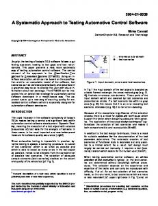
requirements is to specify such sequential constraints, for example in the form of an activity diagram [8]. Figure 1 summarizes the steps of the TOTEM system testing methodology. In this paper, we will focus on activities A2, A3, and A5 and leave the evaluation of their relative cost to future work. A1 is the first step where we check that the provided UML diagrams are complete and fulfill our testability requirements. A4 is not addressed here though it is an important contribution to test requirements [5] and is to be addressed by future work. However, activities A2, A3, and A5 constitute by themselves a self-contained methodology and the fact that A4 is missing will not affect the validity and usefulness of what we present in this paper.
A1: Check completeness, correctness, consistency of the Analysis model
A2: Derive Use Case dependency sequences
A3: Derive test requirements from system sequence diagrams
A4: Derive test requirements from system class diagram
A5: Derive variant sequences
A6: Derive requirements for system testing
A7: Derive test cases for system testing
A8: Derive test oracles and harness
Figure 1 – TOTEM System Test Steps (activity diagram) Once testability is ensured (A1), we go on to derive test requirements from the different artifacts (from A2 to A5). Then these requirements are merged into one set of test requirements, thus avoiding redundancy and combining test requirements into one test plan. A7 and A8 are concerned with generating the test cases and code for oracles, and embedding them into executable test drivers. These steps are typically performed at a later stage once detailed design information is available and they will not be discussed
5
Carleton University TR SCE-01-01- Version 4
Revised June 2002
here. One important objective of TOTEM is to provide a systematic methodology to perform the activities presented above and to automate them to the maximum extent possible. 3
GENERATING SYSTEM TEST REQUIREMENTS AT THE COMPLETION OF ANALYSIS
This section covers the steps A2, A3, and A5 of the TOTEM system test methodology in a chronological order, covering each activity with one subsection. 3.1
Generating Use Case Sequences
Use cases are a first good source for deriving system test requirements. After all they represent the high level functionalities provided by the system to the user . But they are usually not independent. Not only they may have and dependencies but they may also have sequential dependencies [5, 8] which stem from the logic of the business process the system supports. When planning test cases for use cases, we need to identify possible execution sequences of use cases. We aim at “covering” such use case sequences during testing as they may trigger different failures. In this section, we will provide an overview of the principles underlying the representation and generation of possible use case test sequences. These principles are formalized by the description of algorithms provided in Appendix H. In a subsequent subsection, we provide a detailed, illustrative example based on the Library system. 3.1.1 Representation of Use Case Sequential Dependencies We represent sequential dependencies between use cases by the means of an activity diagram for each actor in the system [8]. Such a representation will facilitate the identification and visualization of these dependencies by application domain experts, as activity diagrams are easy to interpret. In such a diagram, the vertices are use cases and the edges are sequential dependencies between the use cases: An edge between two use cases (from a tail use case to a head use case) specifies that the tail use case must be executed in order for the head use case to be executed, but the tail use case may be executed without any execution of the head use case. In addition, specific situations require that several use cases be executed
6
Carleton University TR SCE-01-01- Version 4
Revised June 2002
independently (without any sequential dependencies between them) for another use case to be executed, or after the execution of this other use case. This is modeled by join and fork synchronization bars in the activity diagram, respectively. To be more precise, the vertices of our activity diagram are extended use cases, as described in [5]. Whether explicitly specified or not, use cases have parameters that determine the behavior they can exhibit, as well as output values (results of their execution). Extended use cases require Formal use case parameters to be defined by providing their type (either basic UML type or user-defined type) and kind, i.e., whether they are in, out, or inout, like for operations. Furthermore, Actual use case parameters are represented in the activity diagram by simply listing them between brackets. The reason to have actual parameters in this context is to show the dependencies between parameters during the execution of a path in the activity diagram, e.g., an out parameter from one use case being an in parameter of a subsequent use case. The use cases are grouped into swimlanes5, according to their responsibilities in terms of manipulated objects (application domain classes). Each swimlane represents what is referred to as Entity-life histories in [11]. Entity-life histories describe the life cycle of an application domain object (in the Analysis class diagram) from their creation in the system, through all the functions being performed on them, to their destruction. If not related by cross-swimlanes sequential dependencies or synchronizations (or their transitive closure), use cases from different swimlanes are independent, and thus can occur independently, in any order. This is modeled by the concept of interleaving when modeling sequences in the Fusion method [9]. An example from our Library system (see use case diagram in Appendix A) can be found in Figure 2 (use cases are identified by their name and also, for brevity, by a capital letter from A to K). Formal parameters are provided for each use case in Appendix B. Such definitions should be part of any template to define use cases so as to make them testable [5]. Actual parameters, such as uid (user ID), are visible within each action state in the activity diagram and can be mapped to their corresponding formal parameter based on their ordering. 5
Swimlanes partition an activity diagram to assign responsibilities for actions to objects [6].
7
Carleton University TR SCE-01-01- Version 4
User
Revised June 2002
Loan
Item
Title
Add User (uid)
A
I G
Add Title (isbn)
Library
K
Monitor System
Add Item (isbn, itemid)
Borrow LoanCopy (uid, itemid)
D
J
Remove Title (isbn) E Collect Fine (uid, itemid)
Renew Loan (uid,itemid)
B
F
Remove Item (itemid)
Return LoanCopy (uid, itemid)
H
Remove User (uid) C
Figure 2 – Use Case Sequential Constraints for the Librarian (activity diagram) This activity diagram is built for the Librarian (actor) and, in general, one diagram should be provided for each actor. If we use this example to illustrate some of the concepts presented above, the sequential dependency between AddTitle and RemoveTitle
specifies that AddTitle must be executed first in order to execute
RemoveTitle,
but the execution of AddTitle does not require the execution of
RemoveTitle.
Both AddUser and AddItem need to be executed before BorrowLoanCopy
can, as modeled by a join synchronization. Regarding actual parameters, isbn is required as an input by RemoveTitle (and matches formal parameter isbn: Integer in Appendix B)
and uid and itemid are input parameters required by the BorrowLoanCopy use case
(matching formal parameters uid: Integer and itemid: Integer). 3.1.2 Generation of Use Case Sequences In this context, our objective is to generate legal sequences of use cases (according to the sequential dependencies specified in the activity diagram), in a fully automated way. Those use case sequences will constitute the first component of the system test requirements.
8
Carleton University TR SCE-01-01- Version 4
Revised June 2002
Paths in the activity diagram represent a possible life history for an object type (e.g., path6 AddUser.RemoveUser for class User) or a combination of object types (e.g, path AddTitle.AddItem.RemoveItem.RemoveTitle
for classes Title and User). The
activity diagram in Figure 2 specifies an infinite number of paths, a property due to the loop between use cases CollectFine and RenewLoan. However, given that a loan can be renewed only twice, the number of paths between use cases BorrowLoanCopy and ReturnLoanCopy
equals 14, thus leading to 130 paths in the whole activity diagram7.
Note that when the maximum number of times a loop can be taken is too high (thus leading to too many paths), we can use a strategy similar to what is used to test loops in code (i.e., we can make sure that each loop is bypassed – if possible, taken only once, a representative or average number above 1, and a maximum number of times). Paths are first determined through a simple depth-first search (that accounts for loops) in the directed graph corresponding to our activity diagram. Then we need to determine dependencies in terms of actual parameter values between the use cases in a path. For instance, in path AddTitle.AddItem.RemoveItem.RemoveTitle, parameter isbn for use case AddItem must be identical to parameter isbn in AddTitle. Similarly, the itemid
(resp. isbn) removed in use case RemoveItem (resp. RemoveTitle) must be the
one added in AddItem (resp. AddTitle). Such dependencies among actual parameter values are needed in order to identify the data flow between use case executions, something that will be necessary for the generation of test input data. They can simply be determined based on the actual parameters in our activity diagram, such parameters serving as placeholders for actual values. We can simply document such dependencies by adding actual parameters into the use case sequences, which are referred to as parameterized use case sequences. Using the example path above, we obtain: AddTitle(isbn).AddItem(isbn,itemid).RemoveItem(itemid).RemoveTitle(isbn)
6
We use ‘.’ to denote the sequence of two use cases in a path (like regular expressions). Given that node E can appear at the most twice in a path, there are 14 possible paths between nodes D and F (a tree representing these paths is easy to build). Nodes A, I, and G (with I always before G) must be taken before D, thus leading to 3 possibilities (A.I.G, I.A.G, I.G.A). The same situation occurs after node F, with nodes C, H, and J. Then there are 3 x 3 x 14 = 126 paths involving all nodes from A to J. There exist four other paths: K, I.J, I.G.H.J, and A.C.
7
9
Carleton University TR SCE-01-01- Version 4
Revised June 2002
If we execute any path between AddTitle and RemoveTitle, such as the one above which is an output of the depth first search, use cases AddTitle and AddItem are executed at most once. That is, at best, each title corresponds to only one item in the library. If we want to test our Library system under more realistic situations, we obviously need more than one item per title and more than one loan per user and item. We also need to proceed with large number of users, items, and loans if we want to test the scalability of our system. As a consequence, our construction of use case sequences may need to instantiate several times, with different values, the parameters of a number of use cases specified by the activity diagram. The number of times use case parameters must be instantiated is determined by the information provided by tester in terms of the scale of the test to take place, e.g., the (average) number of users, or items per title. In the simple example where 2 items and 1 title must be created, we get two instantiated use case sequences (S1, S2) from the parameterized sequence above, where title1, item1, and item2 are symbolic values8 for the isbn and itemid parameters: S1:AddTitle(title1).AddItem(title1,item1).RemoveItem(item1).RemoveTitle(title1) S2:AddTitle(title1).AddItem(title1,item2).RemoveItem(item2).RemoveTitle(title1)
Similarly, the tester must indicate constraints on dependency loops, e.g., in our Library system use case RenewLoan can be executed at most twice for a particular loan. Furthermore, the test strategy for loops needs to be specified in ways that are similar to code loop testing, as discussed above. This is necessary to determine which use case sequences need to be tested. At this point, all instantiated use case sequences need to be combined to generate complete sequences to be tested. This is due to the fact that the sequences we have generated so far are incomplete as synchronizations were not accounted for. For our simple example above (S1,S2), a possible combined sequence is: AddTitle(title1).AddItem(title1,item1).AddItem(title1,item2). RemoveItem(item2).RemoveItem(item1).RemoveTitle(title1)
8
They are just place holders for values to be assigned based on formal parameters type analysis.
10
Carleton University TR SCE-01-01- Version 4
Revised June 2002
The combination of instantiated use case sequences must be carefully performed as it must preserve the use case dependencies and avoid the duplication of instantiated use cases. This can be formalized by the concept of interleaving [9] (where || denotes interleaving in a sequence) and implemented as such to derive possible sequences. In our simple example, the two sequences (S1,S2) would be combined as: AddTitle(title1).((AddItem(title1,item1).RemoveItem(item1))
|| (AddItem(title1,item2).RemoveItem(item2))).RemoveTitle(title1) Let us take a more general example and suppose we have to combine the two following sequences: prefix1.X.middle1.Y.suffix1 prefix2.X.middle2.Y.suffix2
where X and Y represent common instantiated use cases and the prefix/middle/suffix keywords represent any subsequence. It is implied that prefix1 and prefix2 (and middle1
and middle2, and suffix1 and suffix2, respectively) are instantiated use case
sequences that do not have common elements (same use case with the same symbolic values). They show different indices so as to express that their corresponding subsequences are different. In this situation, the resulting set of sequences to test can be modeled and derived using interleaving: (prefix1 || prefix2).X.(middle1 || middle2).Y.(suffix1 || suffix2)
From this example, we can understand what the general procedure to combine instantiated use case sequences will look like. Common instantiated use cases will be identified across pairs of sequences and, for each pair, all the subsequences in between each common, instantiated use cases will be combined using interleaving. This procedure will be performed for all pairs of sequences extracted from the activity diagram. Furthermore, when performing the interleaving to generate sequences, we will only sample a subset of all possible resulting sequencing in order to avoid a combinatorial explosion.
11
Carleton University TR SCE-01-01- Version 4
Revised June 2002
3.1.3 Summary To summarize (Figure 3), parameterized use case sequences are derived from the activity diagram. Given the information provided by the tester about the scale of testing, these sequences are instantiated (with symbolic values) and then combined using an iterative procedure in order to obtain the final instantiated use case sequences to be tested. In a subsequent step, which is out of the scope of this paper, actual values for these symbolic values will have to be (e.g., randomly) generated by analyzing the type of the corresponding use cases’ formal parameters. Sequential Constraints (Activity Diagram)
1 Extract UC Sequences
Step 1
Parameterized UC Sequences
Test Scale Information
2 Analyze Parameter Dependencies
Step2
Instantiated UC Sequences (incomplete)
3 Extract Test Sequences
Step3
Complete Test UC Sequences
Figure 3 –Steps for Extracting Use Case (UC) sequences to be tested All three activities in Figure 3 must be automated. We discuss below the complexity of doing so: 1 The derivation of parameterized use case sequences from the (augmented) UML activity diagram can easily be done with a depth first search through a directed graph capturing the activity diagram in Figure 2. 2 The derivation of instantiated use case sequences from the test scale information provided by the tester does not require any complex algorithm either. Recall that we
12
Carleton University TR SCE-01-01- Version 4
Revised June 2002
want to cover all parameterized test sequences. In addition, we want now to “cover” as many instances of each class as specified by the tester. Typically, parameterized sequences will be instantiated several times so as to fulfill the test scale specification. 3 This is the most complex activity to automate. It requires the identification of common instantiated use cases across sequences, which indicate either a synchronization or a common initial subsequence. Subsequences between synchronizations are then interleaved to generate complete use case sequences. However, as we will see, it is not practical, in most cases, to generate all possible sequences so some random sampling is likely to be necessary. We will now illustrate the details of each step by using our working example. 3.1.4 Example In this section we show how, in the case of our Library system, the three activities in Figure 3 produce complete use case sequences to be tested. In Step 1, parameterized use case sequences are derived from a directed graph (Figure 4) corresponding to the activity diagram that describes sequential dependencies between use cases (Figure 2). Such a directed graph can be derived by transforming join and fork synchronizations into regular edges, e.g, join synchronization from activities A and G to activity D in Figure 2 are transformed into an edge from A to D and an edge from G to D (Figure 4). From this directed graph, a depth-first search, that takes into account that edge E (use case RenewLoan) cannot be taken more than twice, produces 60 paths that we show as a tree in Figure 5. Those path represent possible sequences of parameterized use cases that can be executed. In this figure, any path that begins with Start.A.D eventually reaches F and continues with either C.End or H.J.End. Due to space constraints, we omitted this last alternative in all these paths (denoted with ‘…’). For the same reason, all the branches from D are omitted in the paths that start with Start.I.G.D.
13
Carleton University TR SCE-01-01- Version 4
Revised June 2002
Start
A
I
K
G D
B
E
F C
H J
End
Figure 4 – Directed Graph corresponding to activity diagram in Figure 2. Start
C
End
D
G
F
E
B
F
…
I
B
F
…
A
F E
…
E
C
H
End
J
F
End
…
B
F
…
B
F
F
F
…
…
E
B
F
E
…
E
B
F …
B
F
F
F
…
…
K
J
D
H
…
J
End
End
End
…
…
Figure 5 – Tree derived from directed graph in Figure 4 Step 2 in Figure 3 requires test scale information. Let us assume that the tester wants: 2 users, 3 titles, 2 items per title, 1 loan per user, no renew or collect fine for loans, and no system monitoring. Such a situation, though not representative of a realistic use of the Library system, is deemed adequate as it implies a small number of sequences (7 out of 60 are now possible) but allows us to illustrate all the steps. For that particular example, Table 1 summarizes the requirements for the derivation of instantiated use case sequences. The first row presents the parameterized use case sequences to be tested. The
14
Carleton University TR SCE-01-01- Version 4
Revised June 2002
last sequence, using interleaving, models 9 sequences9. The second row shows, for each class, the parameter instances (using place holders as symbolic values) corresponding to the test scale specified by the tester. The instantiation of parameterized use case sequences is aimed to replace actual parameters with symbolic values as derived from the test scale information. Note that, in Table 1, Loan instances are characterized by pairs (uid, itemid)
and that we do not use symbolic values for Loan instances. This stems
from the fact that a loan is uniquely identified by a user and item and that there is no use case parameter of type Loan. Parameterized Use Case Sequences
Parameter Instances (Symbolic values)
-
A(uid).C(uid) I(title).J(title) I(title).G(title, item).H(item).J(title)
-
(A(uid)||I(title).G(title,item)).D(uid,item). F(uid,item).(C(uid)||H(item).J(title))
-
Users (2): u1, u2 Titles (3): t1, t2, t3 Items (one per title): (t1,i11), (t1,i12), (t2,i21), (t2,i22), (t3,i31), (t3,i32) Loans (one per user and item): pairs (u1, i22) and (u2, i32)
-
Table 1 – Requirements for the derivation of instantiated use case sequences. The instantiation selects one parameterized sequence at a time, assigns actual parameters with symbolic values, and starts again from the first sequence if symbolic values are still to be assigned after covering all sequences. So the instantiated use case sequences we obtain are, to some extent, arbitrary, as it selects parameterized sequences and symbolic values in arbitrary orders. But what is important is that these sequences fulfill our requirements: They cover the parameterized use case sequences and match the test scale specification. Regarding our example, following the orders in Table 1, we would obtain the following 8 instantiated use case sequences: Seq1: A(u1).C(u1) Seq2: I(t1).J(t1) Seq3: I(t2).G(t2, i21).H(i21).J(t2)
9
There are three possibilities for the two interleavings in the sequence (e.g., A||I.G produces sequences A.I.G, I.A.G, and I.G.A), and thus a total of 9 sequences.
15
Carleton University TR SCE-01-01- Version 4
Revised June 2002
Seq4: I(t3).A(u2).G(t3,i32).D(u2,i32).F(u2,i32). C(u2).H(i32).J(t3)
Seq5: I(t1).G(t1, i11).H(i11).J(t1) Seq6: I(t1).G(t1, i12).H(i12).J(t1) Seq7: A(u1).I(t2).G(t2,i22).D(u1,i22).F(u1,i22).H(i22). C(u1).J(t2)
Seq8: I(t3).G(t3, i31).H(i31).J(t3) We can see that we end up with 4 and 2 instances of the 3rd and 4th sequence in Table 1, respectively. This is necessary in order to cover all parameter instances. Another issue is that some sequences are included in others. What we mean is that all the instantiated use cases in one sequence are present, in the same order, in another sequence. For example, Seq1 and Seq2 are included in Seq7 and Seq5, respectively. In order to decrease the number of sequences, a reasonable heuristic is to keep only sequences that are not included in others. In our example, we would then obtain the following final set of sequences: {Seq3, Seq4, Seq5, Seq6, Seq7, Seq8}. Instantiated use case sequences are then combined together, in a stepwise manner, to produce complete use case sequences to be tested (Step 3 in Figure 3). Each time two sequences are combined10, interleaving of instantiated use case subsequences can occur, thus possibly leading to large numbers of complete sequences to be tested. In practice, a reasonable number of sequences will have to be determined, e.g., by sampling the entire set of sequences in order to maintain the number of test sequences under a threshold. Regarding our example, we illustrate a complete series of interleaving steps leading to a complete test sequence but we only show one resulting test sequence at each step. First, following the order of sequences, Seq3 and Seq4 are combined and produce 495 interleavings11 which include: S:
I(t3).A(u2).I(t2).G(t3,i32).G(t2,i21).D(u2,i32).H(i21). F(u2,i32).C(u2).H(i32).J(t2).J(t3)
10
Recall that common elements must be identified first. Algorithms for the combination of sequences are provided in Appendix H. 11 We use this term as a shorthand for sequences resulting from the interleaving of a pair of sequences. Given two sequences S1 and S2 of length n and m, respectively, the number of interleavings from S1 and S2 is C(m+n, n) = (m+n)!/(n!m!).
16
Carleton University TR SCE-01-01- Version 4
Revised June 2002
Then, Seq5 and S are combined and produce 1820 interleavings which include: S1:
I(t3).I(t1).G(t1,i11).A(u2).I(t2).G(t3,i32).H(i11).G(t2,i21). D(u2,i32).H(i21).J(t1).F(u2,i32).C(u2).H(i32).J(t2).J(t3)
Seq6 and S1 produce 45 interleavings (two elements in common) which include: S2:
I(t3).I(t1).G(t1,i11).G(t1,i12).A(u2).I(t2).G(t3,i32). H(i11).G(t2,i21).D(u2,i32).H(i12).H(i21).J(t1).F(u2,i32). C(u2).H(i32).J(t2).J(t3)
Seq7 and S2 produce 18018 interleavings which include: S3:
I(t3).I(t1).A(u1).G(t1,i11).G(t1,i12).A(u2).I(t2).G(t2,i22). G(t3,i32).H(i11).D(u1,i22).G(t2,i21).F(u1,i22).D(u2,i32). H(i12).H(i21).J(t1).H(i22).C(u1).F(u2,i32).C(u2).H(i32).J(t2) .J(t3)
In this particular case, we perform the interleaving of 2 sequences which have 2 common instantiated use cases (I(t2), J(t2)). The subsequences between them are interleaved as illustrated by the following table. The total number of possible interleavings results from multiplying the number of interleavings of subsequences between common instantiated use cases (18018 = 6 * 3003). Seq7
A(u1).
I(t2).
Common S21
G(t2,i22).D(u1,i22). F(u1,i22).H(i22). C(u1). J(t2)
I(t3).I(t1). G(t1,i11). G(t1,i12). A(u2).
G(t3,i32).H(i11). G(t2,i21).D(u2,i32). H(i12).H(i21).J(t1). F(u2,i32).C(u2).H(i32).
6 interleavings
3003 interleavings
J(t3)
The last step shown here leads to a complete instantiated use case sequence to be tested. Seq8 and S3 produce 276 interleavings (two elements in common, i.e., I(t3) and J(t3)) which include:
S4:
I(t3).I(t1).G(t3,i31).A(u1).G(t1,i11).G(t1,i12).A(u2).I(t2). G(t2,i22).G(t3,i32).H(i11).D(u1,i22).G(t2,i21).H(i31). F(u1,i22).D(u2,i32).H(i12).H(i21).J(t1).H(i22).C(u1). F(u2,i32).C(u2).H(i32).J(t2).J(t3)
To address step A7 in Figure 1, symbolic values will have to be substituted to actual ones. This will require to perform a type analysis of the corresponding formal parameters in the use case descriptions (Appendix B) and generate legal values that
17
Carleton University TR SCE-01-01- Version 4
Revised June 2002
satisfy a number of constraints. This is out of the scope of this paper and will be addressed by future work. 3.2
Identifying Use Case Scenarios
To each use case corresponds an interaction model, i.e., either a collaboration or a sequence diagram. These diagrams show how the use case is realized through the interactions of objects, that is instances of classes in the analysis class diagrams. In practice, such diagrams may be decomposed into several interconnected diagrams, for the sake of legibility. But these diagrams still represent one interaction model describing alternative object interactions, each of them realizing one possible scenario of a use case. In many cases, an interaction diagram models one nominal scenario and a number of error/exceptional scenarios, where the system has to react appropriately. At the analysis stage, interaction diagrams may also be seen as modeling alternative execution sequences of public operations belonging to application domain classes, each alternative sequence capturing a scenario. In the previous section, we have seen how to derive use case sequences that should be part of the test plan. Now, using the interaction diagrams associated with use cases, we have to go down one more level into details, and derive sequences of use case scenarios to be tested. This bears some similarity with the work of [17] on deriving operation sequences from collaboration diagrams. The main difference lies in the fact that the authors make use of low-level design information (e.g., data flow within operations) rather than analysis documents. Furthermore, the issues of initial test conditions and test oracles are not addressed. Let us illustrate the procedure we propose using an example and then summarize this procedure. Figure 6 presents a sequence diagram for the use case Remove Title. The class diagram for our library system and other sequence diagrams that we will use in this example are provided in Appendices C and D, respectively.
18
Carleton University TR SCE-01-01- Version 4
Revised June 2002
: LibrarianTerminal
: Tit leControl
: Tit le
: Item
: Librarian 1:requestTitleInfo(isbn) 1.1:create() 1.2:requestTitleInfo(isbn) 1.2.1A:[Not self.title.isbn->exists(t:Title|t.isbn=isbn)] titleNotExist(isbn) 1.2.1A.1: titleNotExist(isbn)
1.2.1:[self.title->exists(t:Title|t.isbn=isbn)] item[]:=getItem(title) 1.2.1.1: displayTitleInfo(title,item[])
1.2.1.1.1: displayTitleInfo(title.*) 1.2.1.1.2: *[i:=1..title.item->size] displayItemI nfo (it em [i].* )
2: [self.librarianTerminal.titleControl.title->exists(t:Title|t.isbn=isbn)] removeT it le (i sb n) 2.1: removeTitle(title) 2.1.1A: [self.loancopy->select(loancopyStatus=onloan)->size>0 or self.title.titleReservationCounter>0] loanORreservationExist(title,loancopy) 2. 1. 1A.1 :loan ORre serva tionExist(i sbn ) 2.1.1: [self.loancopy->select (loancopyStatus=onloan)->size =0 and self.title.titleReservationCounter = 0] destroy()
2.1.1.1: *[i:=1..self.title.item->size] destroy()
3: exit() 3.1: destroy()
Figure 6 – Analysis Sequence Diagram for Remove Title (after merging it with included use cases) Note that UML conventions for numbering messages in sequence diagrams have been extended to better address alternatives [10]: Capital letters are used to denote alternatives. In Figure 6, message numbered 1.2.1 is the main branch, and message numbered 1.2.1A is the alternative. Given this extension, both sequence and collaboration diagrams can equally be used to derive sequences of use case scenarios as described in this section. We describe here the procedure using sequence diagrams since they are more often used during Analysis than collaboration diagrams (e.g., [8]). 3.2.1 Expressing Sequence Diagrams as Regular Expressions In order to represent them in an analyzable and compact form, the sequence diagrams can be re-expressed as a regular expression whose alphabet are the public methods of the objects playing a role in sequence diagrams. So, for example, for Remove Title, this
19
Carleton University TR SCE-01-01- Version 4
Revised June 2002
would yield the following regular expressions where we use the notation OperationClass to denote which operation is executed and to which class it belongs12: Remove Title -> RequestTitleInfoLibrarianTerminal.createTitleControl.requestTitleInfoTitleControl. ( getItemTitle.displayTitleInfoLibrarianTerminal.displayTitleInfoUser. displayItemInfoUser*. removeTitleLibrarianTerminal.removeTitleTitleControl. (destroyTitle.destroyItem*+loanORreservationExistLibrarianTerminal)+ titleNotExistLibrarianTerminal.titleNotExistUser ).exitLibrarianTerminal.destroyTitleControl
To automate the transition to regular expressions, the sequence diagram can be modeled as a labeled graph (where the labels are the operations) and matrix based algorithms can be used to automatically derive the corresponding regular expression [4]. The next step, in order to be able to identify scenarios, is to re-express the regular expression above in a sum-of-products form (here 3 product terms separated by “+”): RequestTitleInfoLibrarianTerminal.createTitleControl.requestTitleInfoTitleControl. getItemTitle.displayTitleInfoLibrarianTerminal.displayTitleInfoUser. displayItemInfoUser*.removeTitleLibrarianTerminal.removeTitleTitleControl. destroyTitle.destroyItem*.exitLibrarianTerminal.destroyTitleControl + RequestTitleInfoLibrarianTerminal.createTitleControl.requestTitleInfoTitleControl. getItemTitle.displayTitleInfoLibrarianTerminal.displayTitleInfoUser. displayItemInfoUser*.removeTitleLibrarianTerminal.removeTitleTitleControl. loanORreservationExistLibrarianTerminal.loanORreservationExistUser. exitLibrarianTerminal.destroyTitleControl + RequestTitleInfoLibrarianTerminal.createTitleControl.requestTitleInfoTitleControl. titleNotExistLibrarianTerminal.titleNotExistUser.exitLibrarianTerminal. destroyTitleControl
Each product term represent either a use case scenario or a set of scenarios if iteration symbols are present. 3.2.2 Identifying Path Realization Conditions for Product Terms From our example above, we have obtained a regular expression with three product terms (referred to below as Term 1, 2, and 3, respectively). Each term is associated with a number of conditions enabling or disabling its execution. Indeed, associated with each path within a sequence/collaboration diagram, one can derive from the guard conditions associated with these paths, the conjunction of conditions that must be fulfilled for that 12
We do not address here the issue of overloading. In that case, the name is not enough and the operation signatures are required to model sequence diagrams as regular expression.
20
Carleton University TR SCE-01-01- Version 4
Revised June 2002
path to be enabled. Recall we require that these conditions be expressed in the Object Constraint Language (OCL) so as to be unambiguous [21]. So for Term 1 listed above, the path realization condition is: Term1, path realization condition: self.titleControl.title ->exists(t:Title | t.isbn=isbn) and (self.loancopy->select(loancopyStatus=onloan)->size=0 and self.title.titleReservationCounter=0)
In the path realization conditions, the elements that do not take part in a navigation expression, e.g., isbn, can either be parameters of the operation that triggered the use case or strings matching enumeration types, e.g., onloan. Note that OCL guard conditions, which compose the conjuncts of path realization conditions such as the one above, have to be re-expressed as they assume different contexts13 in the interaction diagrams. The transformation should ensure that every guard condition in the path realization condition uses the same context. It is convenient to assume, as a general rule, that the boundary class [8] corresponding to the use case executed14 (e.g., LibrarianTerminal in our example) be used as a common context. For Term 2, the situation is a bit more complex than for Term 1. The path realization condition is: Term2, path realization condition: self.titleControl.title->exists(t:Title | t.isbn=isbn) and (self.titleControl.loancopy->select(loancopyStatus=onloan)-> size>0 or self.titleControl.title.titleReservationCounter>0)
Because the above condition contains a disjunction, it can be satisfied in three ways: Term2, Condition 1: self.titleControl.title ->exists(t:Title | t.isbn=isbn) and (self.titleControl.loancopy->select(loancopyStatus=onloan)-> size>0 and self.titleControl.title.titleReservationCounter>0)
13
We use the OCL definition of context here [21]. In a sequence diagram, the context of an OCL guard condition is the message source class. All attributes and operations of this class can be used directly. Public attributes and operations of other classes can be reached through OCL navigation. 14 There are, in most cases, several boundary classes involved in a use case. But one actor initiates the use case through a specific boundary class. This is this particular class we refer to here.
21
Carleton University TR SCE-01-01- Version 4
Revised June 2002
Term2, Condition 2: self.titleControl.title ->exists(t:Title | t.isbn=isbn) and (self.titleControl.loancopy->select(loancopyStatus=onloan)-> size>0 and self.titleControl.title.titleReservationCounter=0)
Term2, Condition 3: self.titleControl.title ->exists(t:Title | t.isbn=isbn) and (self.titleControl.loancopy->select(loancopyStatus=onloan)-> size=0 and self.titleControl.title.titleReservationCounter>0)
It is important that all three conditions be tested as the implementation may not implement one or more cases correctly and not testing one of them could lead to the nondetection of a fault in the implementation of the path realization condition of Term 2. This issue is related to the literature on testing logic expressions [5]. Complex conditions need to be tested by exercising operation sequences under several alternative conditions. These alternatives correspond to the different combinations of truth values of logical clauses in a path realization condition such that this condition holds true. 3.2.3 Specifying Operation Sequences Having identified the test conditions under which each term is going to be executed and therefore tested, we need to identify the precise operation sequences to be executed for each term. Since product terms may contain iteration symbols (*, +), precise sequences to be tested need to be defined by giving those iteration symbols actual values. We can use a strategy which is similar to what we did earlier to cover use case sequences: The iteration is bypassed (for * only), performed once, an intermediary number of times (possibly a statistical median if available), and a maximum M number of times. Term 3 has no iteration symbol. If we take Term 2 − which is simpler than Term 1 − as a first example, the sequences obtained using this strategy are: Term 2, sequence 1: displayItemInfoUser is bypassed RequestTitleInfoLibrarianTerminal.createTitleControl.requestTitleInfoTitleControl. getItemTitle.displayTitleInfoLibrarianTerminal.displayTitleInfoUser. removeTitleLibrarianTerminal.removeTitleTitleControl. loanORreservationExistLibrarianTerminal.exitLibrarianTerminal.destroyTitleControl
Term 2, sequence 2: displayItemInfoUser is executed once RequestTitleInfoLibrarianTerminal.createTitleControl.requestTitleInfoTitleControl. getItemTitle.displayTitleInfoLibrarianTerminal.displayTitleInfoUser.
22
Carleton University TR SCE-01-01- Version 4
Revised June 2002
displayItemInfoUser.removeTitleLibrarianTerminal.removeTitleTitleControl. loanORreservationExistLibrarianTerminal.exitLibrarianTerminal.destroyTitleControl
Term 2, sequence 3: displayItemInfoUser is executed twice (intermediary value) RequestTitleInfoLibrarianTerminal.createTitleControl.requestTitleInfoTitleControl. getItemTitle.displayTitleInfoLibrarianTerminal.displayTitleInfoUser. 2 displayItemInfoUser .removeTitleLibrarianTerminal.removeTitleTitleControl. loanORreservationExistLibrarianTerminal.exitLibrarianTerminal.destroyTitleControl
Term 2, sequence 4: displayItemInfoUser is executed a maximum M number of times RequestTitleInfoLibrarianTerminal.createTitleControl.requestTitleInfoTitleControl. getItemTitle.displayTitleInfoLibrarianTerminal.M displayTitleInfoUser.displayItemInfoUser .removeTitleLibrarianTerminal. removeTitleTitleControl. loanORreservationExistLibrarianTerminal.exitLibrarianTerminal.destroyTitleControl
The maximum number of iterations M represents the number of items corresponding to a title,
modeled in OCL by title.item->size in the UML interaction diagram. The
specific number of items depends on the test scale information provided by the tester (see Section 3.1). If we now turn our attention to Term 1, which contains 2 iteration symbols: Term 1, sequence 1: RequestTitleInfoLibrarianTerminal.createTitleControl.requestTitleinfoTitleControl. getItemTitle.displayTitleInfoLibrarianTerminal.displayTitleInfoUser. removeTitleLibrarianTerminal.removeTitleTitleControl. exitLibrarianTerminal.destroytitleControl Term 1, sequence 2: RequestTitleInfoLibrarianTerminal.createTitleControl.requestTitleinfoTitleControl. getItemTitle.displayTitleInfoLibrarianTerminal.displayTitleInfoUser.display ItemInfoUser.removeTitleLibrarianTerminal.removeTitleTitleControl. destroyTitle.destroyItem.exitLibrarianTerminal.destroyTitleControl Term 1, sequence 3: RequestTitleInfoLibrarianTerminal.createTitleControl.requestTitleinfoTitleControl. getItemTitle.displayTitleInfoLibrarianTerminal.2 displayTitleInfoUser.displayItemInfo2User .removeTitleLibrarianTerminal.remo veTitleTitleControl.destroyTitle.destroyItem .exitLibrarianTerminal.destroyTitleControl Term 1, sequence 4: RequestTitleInfoLibrarianTerminal.createTitleControl.requestTitleinfoTitleControl. getItemTitle.displayTitleInfoLibrarianTerminal.M displayTitleInfoUser.displayItemInfoUser .removeTitleLibrarianTerminal.remo veTitleTitleControl. destroyTitle.destroyItemM.exitLibrarianTerminal.destroyTitleControl
In the sequences above, the two iteration symbols are inter-dependent. More specifically, they must be the same since they are both determined by the number of items associated with a title. In general we have to expect such dependencies between iteration symbols. 23
Carleton University TR SCE-01-01- Version 4
Revised June 2002
Such dependencies can automatically be detected from the sequence diagram, where iteration conditions are specified. In Figure 6, the iteration conditions of both iterative operations in Term 1 are identical: [i:=1..self.title.item->size]. Multiple iterations in a term do not have to share identical iteration conditions and may exhibit more complex relationships. This is the type of analysis that automation needs to support. 3.2.4 Identifying Test Oracles Now assuming we have defined the operation sequences to be executed and tested, we need to derive test oracles for each tested sequence. It is crucial to address efficiently the oracle problem in order to make automated testing possible. The main source for deriving a test oracle is the post-condition of operations in a sequence, which are defined using OCL. If we take Sequence 4 in Term 1 as an example, we note that only the two removeTitle operations have a non-trivial post-condition. The removeTitleLibrarianTerminal operation merely delegates to removeTitleTitleControl (see sequence diagram in Figure 6) and they, therefore, have the same post-conditions (but defined using a different context, as expected). From the data dictionary, where all model elements are defined and where preand post-conditions are assumed to be provided, we can extract: TitleControl::removeTitle(title, loancopy):void post: self.title=self.title@pre-set{title} and item.allinstances.title->select(isbn = title.isbn)->size=0
This expression’s context is a titleControl object, created to control the execution of the Remove Title use case. This object has, however, disappeared by completion of the use case as the last message triggers it destruction and cannot be used as context object in the test oracle expression15. Then, the oracle that needs to be checked by the test driver for our example is : Title.allInstances= Title.allInstances@pre-set{title} and Item.allInstances.title->select(isbn = title.isbn)->size=0
We therefore need, in general, to transform the postconditions to make them usable as test driver oracles. A general transformation rule is that self should be removed in the
15
It is typical [9] to instantiate a control object during a use case’s initiation and then to dispose of it when its corresponding use case is completed.
24
Carleton University TR SCE-01-01- Version 4
Revised June 2002
postcondition and allInstances should be used to refer to the instances of the class following self in the navigation expression (Title here). Then select can be used, if necessary, to select the appropriate instances and check the required condition. It is, however, not necessary in the above example as all Title instances are of interest. In the above oracle expression, just after the select bracket, isbn is not the result of a navigation expression and is a parameter of an operation triggered by the use case on the boundary class LibrarianTerminal:: requestTitleInfo(). Such parameters, defined in what Binder calls extended use cases [5], were first introduced in Section 3.1 for the identification of use case sequential dependencies. We will see that they play an important role at a later stage (Section 3.3). We discuss further this issue in Section 4. The case above is rather simple since, as mentioned above, only two operations have a non-trivial and identical post-condition. In the general case, the conjunction of postconditions in the sequence of operations has to be used to determine the test oracle. This may lead to complex cases where, for example, one subsequent operation’s postcondition clause cancels out a former post-condition clause. This issue will be addressed by future work. A simpler alternative, that does not require complex OCL expression analyses and transformations but entail more code instrumentation, is to systematically execute assertions that instrument pre/post-conditions and class invariants at the entry/exit of each operation and raise an exception when they are violated. This was recently suggested as a potential solution to the oracle problem in [3] and [7]. In [7], the authors investigate whether instrumented contracts, defined during Analysis, can be used as a substitute to hard-coded test oracles in the test drivers and whether they help with diagnosing failures and locate faults. Based on a case study, results indicate that, in roughly 80 percent of the cases, instrumented contracts are good enough substitutes to hard-coded oracles in test drivers. 3.2.5 Constructing Decision Tables Once we have, for a given use case, identified the operation sequences to be tested, their initial conditions and oracles, we can formalize all this in a decision table that will be used as a formal set of test requirements, which will be part of the test plan. For
25
Carleton University TR SCE-01-01- Version 4
RemoveTitle,
Revised June 2002
the corresponding decision table is provided in Table 2. Decision tables
for the other use cases of the Library example are provided in Appendices E, F, G. Variants (use case J)
Condition Section
Action Section Messages to Actor
State Change
A
B
C
D
E
I
II
III
j1
Yes
No
No
No
No
No
No
Yes
Yes
j2
No
Yes
No
No
No
No
Yes
Yes
No
j3
No
No
Yes
No
No
No
Yes
Yes
No
j4
No
No
No
Yes
No
No
Yes
Yes
No
j5
No
No
No
No
Yes
Yes
No
No
No
Table 2 – Decision Table for RemoveTitle (use case J) Each row in Table 2 is what is called in testing terminology a variant [5]. Test cases should cover all variants, at least once. Due to the fact that a product term (Section 3.2.2) is tested instantiating iteration symbols into several operation sequences (Section 3.2.3), each variant will be covered by several test cases, one for each tested operation sequence. The columns model the initial conditions in which test cases must be run, the actions that are taken as a result of running the test cases. Namely, this corresponds to system state changes and output messages being sent to actors. Further details describing the columns of Table 2 are provided below. Initial Conditions16: A: self.titleControl.title ->exists(t:Title | t.isbn=isbn) and self.titleControl.loancopy->select(loancopyStatus=onloan) ->size=0 and self.titleControl.title.titleReservationCounter=0 B: self.titleControl.title ->exists(t:Title | t.isbn=isbn) and self.titleControl.loancopy->select(loancopyStatus=onloan) ->size>0 and self.titleControl.title.titleReservationCounter>0 C: self.titleControl.title ->exists(t:Title | t.isbn=isbn) and self.titleControl.loancopy->select(loancopyStatus=onloan) ->size>0 and self.titleControl.title.titleReservationCounter=0
16
The context of OCL expressions A-E is the boundary class for the corresponding use case, i.e.,
LibrarianTerminal.
26
Carleton University TR SCE-01-01- Version 4
Revised June 2002
D: self.titleControl.title ->exists(t:Title | t.isbn=isbn) and self.titleControl.loancopy->select(loancopyStatus=onloan) ->size=0 and self.titleControl.title.titleReservationCounter>0 E: not self.titleControl.title->exists(t:Title | t.isbn=isbn)
Messages to Actor User: I:
titleNotExist
II:
loanReservationExist
III: displayTitleInfo.displayItemInfo*
A * associated to a message, like in case III above, indicates that the message may be sent several times. This number of iterations is determined by the operation sequence that is being executed, as discussed in Section 3.2.3. State Changes: Title.allInstances= Title.allInstances@pre-set{title} and Item.allInstances.title.select(isbn = title.isbn)->size=0
In this example, there is only one possible state change or no state change at all. But in general, we have to expect that some alternative state changes will be possible. Based on the example above, we can now summarize the steps of the procedure used to extract a decision table for each use case. Our source of information is an Analysis model described in UML, which is complying with our testability requirements (summarized in Section 4). 1. For each use case, model possible operation sequences in a regular expression having a sum-of-product terms form, where the alphabet are the public operations of the objects involved in the use case sequence diagram. 2. For each product term, which models a set of possible operation sequences, determine the initial conditions that must be set up by the test driver to be able to execute any of the sequences matching the term. 3. Specify precisely the operation sequences that match the term to be executed and tested. We use a strategy similar to loop testing but in a different context. 4. Identify test oracles by making use of the operation post-conditions specified in the Analysis model (data dictionary).
27
Carleton University TR SCE-01-01- Version 4
Revised June 2002
5. Formalize all the information above into decision tables that follow the format proposed above, which is similar to what is described in [5]. 3.3
Generating Variant Sequences
If we assume that each use case has a decision table such as the one presented above, we need to go further and devise a sequence of operations to be tested over an entire use case sequence (as defined in Section 3.1). In other words, we need to go from use case sequences to use case variant sequences, using use case decision tables. Assuming we would have a use case sequence of three use cases A.B.C, having respectively a number of variants |A|, |B|, and |C|, the maximum number of variant sequences would then be |A| * |B| * |C|. As described in Section 3.2.5, one variant corresponds to a possible path realization condition for one of the product terms in the interaction diagram regular expression. A variant may require several test cases, as iteration symbols may be present in the corresponding product term, which therefore requires several operation sequences to be tested. More specifically, up to 4 test cases (number of iterations sets to 0, 1, an intermediary number, and a maximum M) may be needed if we use the sequence test strategy presented in Section 3.2.3. Note that, at the beginning of a use case variant sequence, the system is in its initial state. An issue to be noted is that the test scale specified by the tester (Section 3.1.1) determines what use case variant sequences are possible. The scale of testing must then be chosen carefully if the tester wants to consider all the possible use case variants sequences in the decision tables. To illustrate this, let us take the following simplistic example: In the Library system testing, assume the tester only wants one title and one item for this title (no user or loan, …). In this situation, the only possible use case sequence to be tested (following what is described in Section 3.1) is: AddTitle(t).AddItem(i). RemoveItem(i).RemoveTitle(t).
Since we do not have any loan for the item or
reservation for the title, variants 2, 3, and 4 for use case RemoveTitle are not possible (see Table 2). In addition, variant 5 (removing a title that does not exist) for use case RemoveTitle(t)
is also impossible because title t is created in the sequence (the
parameter of RemoveTitle is the one of AddTitle). Therefore, RemoveTitle variant 1 is the only possibility. For similar reasons, RemoveItem variant 1 is the only possible
28
Carleton University TR SCE-01-01- Version 4
variant.
Then,
the
only
Revised June 2002
possible
use
AddTitle1.AddItem1.RemoveItem1.RemoveTitle1.
case
variant
sequence
is
This variant sequence is the case
where a title is added, one corresponding item is added, and then the item and title are subsequently removed. This corresponds to the first (nominal) variant in each of the decision tables in Appendices E, F, G and Table 2. In practice another issue may arise. Some variant sequences may turn out to be impossible as some of the variants are not compatible. A variant bi of B is incompatible with a variant aj of A if the state of the system after the execution of aj is contradicting (a part of) the initial condition of bi. This is an issue that needs to be addressed as the detection of impossible variant sequences need to be supported to help generate clean, concise test requirements. 4
TESTABILITY
Since the application of the UML notation is not constrained by any particular, precise development method, one can find a great variability in terms of the content and form of UML artifacts, whether at the analysis or design stages. However, the way UML is used determines the testability of the UML artifacts. That is, in our context, the ease with which they can be used to support testing activities and the derivation of test artifacts (test requirements, cases, oracles, drivers). Moreover, since automation is a crucial consideration here, our methodology and its associated algorithms have precise requirements regarding the information to be contained in UML artifacts. Thus, in the previous sections, we made a number of assumptions regarding the way a UML analysis model is to be developed. Those assumptions were carefully thought out and are referred to as testability requirements. We discuss and justify them in this section, using the metamodel in Figure 7, and explain how they can be automatically verified in the next Section (Section 5). The very first of those testability requirements concerns the sequential constraints between use cases, in addition to the other dependencies shown in the use case diagram (class UCSequentialDependencies class in Figure 7). We decided to build one activity diagram per actor in the system to model such dependencies (see Section 3.1 and Figure
29
Carleton University TR SCE-01-01- Version 4
Revised June 2002
2). These activity diagrams capture the sequential dependencies between the use cases related to the actors. UCSequentialDependencies 1 1
1..*
1..*
1
Analysis Document
Interaction Diagram 1
1..*
Extended Use Case 1
1
1 Sequence Diagram
Collaboration Diagram
Class Diagram 1..*
Class 1..*
Invariant
1
1..* *
Data Dictionary Description Precondition
1
1
Operation
1..* 1
1 1
Postcondition 1
Figure 7 – Meta-model describing Analysis testability requirements for TOTEM Then each use case is described using an interaction diagram, which in UML is either an interaction diagram or a collaboration diagram. We assume that these diagrams use OCL for the description of the alternative object interactions (guard conditions), and extended the UML numbering rules for messages in interaction diagrams (see Section 3.2), thus making them unambiguous (see Figure 6). In addition, we are defining and using extended use cases (as described in [5]) that specify, among other things, information about the parameters that determine the behavior to be exhibited. For example, we show in Section 3.2.2 that isbn is a formal parameter for the Remove Title use case. We further show that the values of these parameters need to be carefully chosen to execute some of the variant sequences (Section 3.3). Finally, the data dictionary is assumed to provide − in addition to an informal description of classes, attributes, and operations − the contracts (pre- and post-conditions for the operations) and class invariants in OCL. For example, we presented such a post-condition in Section 3.2.4, for method removeTitle in class TitleControl.
30
Carleton University TR SCE-01-01- Version 4
Revised June 2002
Testability requirements are a trade-off between better testability and the effort overhead they entail during Analysis and Design. We believe that having a description of the business model supported by the system (the activity diagram capturing sequential constraints between use cases), as well as precise definitions for operations and classes (contracts), is not only relevant for testing but also a sound practice for a precise and rigorous Analysis17. A similar argument can be made for precise OCL guard conditions in the sequence diagrams describing each use case. Furthermore, [5] indicates that guard conditions should be expressed in an executable syntax and, in the context of the UML, OCL is a natural choice. Overall, our testability requirements seem realistic and justified, though their costs and benefits during analysis are to be investigated further through case studies. Our view on testability is related to functional and behavioral models. In other words, how easily can we derive complete test artifacts from UML diagrams? There exist other, complementary testability definitions that are more related to source code and structural models. Built-in test support (e.g., set and get methods for attributes) can improve two important components of testability: observability (retrieving the state of the system) and controllability (setting the system in a particular state) [5]. From a completely different perspective, [1] assesses testability by quantifying the effort required for different unit test strategies based on measures of control flow graphs. 5
AUTOMATION
The purpose of this section is to describe what should be the internal structure of a tool to support our testing methodology, both in terms of packages and, when relevant, at the class level. This led us to the development of a prototype tool that implements the core architecture needed by the TOTEM strategy. Another benefit of this modeling exercise is that we recap, in a structured manner, how all the concepts, representations, and algorithms introduced earlier relate to each other. Automation of the different steps of the TOTEM strategy requires that information provided by UML diagrams is available, in full conformance to our testability requirements. The meta-model in Figure 7 is therefore one of the core packages 17
This view is supported by a number of articles and books (two examples are [9, 14]).
31
Carleton University TR SCE-01-01- Version 4
Revised June 2002
(RequirementsMetamodel) of the TOTEM tool (see Figure 8), which serves as a repository of UML diagrams’ information. The other packages in Figure 8 concern the automatic construction of system test requirements (SystemTesting, which classes are described in Figure 9), and parsing UML and OCL information. Since these diagrams are built using UML case tools, a first solution is to use the API provided by these tools to access UML diagrams’ information. An alternative relies on an XMI representation of the diagrams, which are exported by an increasing number of case tools, and for which parsers already exist. This second solution has the advantage of not depending on a particular case tool, as long as the tool is able to produce XMI files.
Requirements Metamodel
System Testing
Business Process Diagram
Use Case Sequence
Interaction Diagram
Interaction Regular Expression
XMI parser
OCL parser
Figure 8 – Packages of the TOTEM System Testing tool RequirementsMetaModel
depends on OCLparser as it needs to verify the correctness of
OCL expressions. Depending on our test oracle strategy (Section 3.2.4), SystemTesting may need to manipulate OCL expressions to compare or transform them. Testability requirements can be automatically verified in order to make sure UML Analysis models are compliant before performing any further analysis for testing purposes: -
An activity diagram describing sequential dependencies between use cases must be available for each actor;
-
Each use case must be described by an interaction diagram;
32
Carleton University TR SCE-01-01- Version 4
-
Revised June 2002
Interaction diagrams must make use of adequate numbering conventions for messages;
-
Guard conditions for messages in interaction diagrams as well as class invariants, pre- and post-conditions must use the OCL.
Then, once the UML models have been shown to be compliant with testability requirements, the different activities described in Section 3 can be automated: -
Given an activity diagram, producing use case sequences to be tested as described in Section 3.1 needs to be automated. We provide algorithms for the most complex
parts
of
this
process
SystemTestingRequirements
(all
the
parameterized
use
(Appendix
H).
In
Figure
9,
class
initializes (1) the composition allParamUCSeq case
sequences)
with
class
ParamUCSeq
(parameterized use case sequence) from the activity diagram, (2) the composition allOriginalInstUCSeq (all the original instantiated use case sequences) with
class InstUCSeq (instantiated use case sequence) from the test scale information, and then (3) the composition completeUCSeq (the complete set of use case sequences to be tested) with InstUCSeq ; -
The generation of use case scenarios from interaction diagrams is formalized, for each use case, as a decision table and modeled in the SystemTesting package (Figure 9): -
Regular expressions describing interactions diagrams as method sequences, each unique sequence describing a use case scenario.
-
Path realization condition and operation sequences for the product terms in the regular expressions (i.e., the decision table variants).
-
Test oracles for operation sequences. As discussed in Section 3.2.4, this requires complex manipulations of OCL expressions, i.e., pre- and postconditions of operations in sequences. For example, we need to be able to determine whether two OCL expressions contradict or subsume each other. All this is not required though if we decide to use instrumented contracts, as discussed above.
33
Carleton University TR SCE-01-01- Version 4
-
Revised June 2002
The next step is to produce variant sequences (Section 3.3) using both use case sequences and scenario decision tables. One important automation issue is the detection of incompatible variants across decision tables. 1 System Testing
1
allOriginalInstUCSeq
completeUCSeq
1
1
1..*
Interaction Regular Expression
1
1
allParamUCSeq 1..* 1..*
Operation Sequence
ParamUCSeq
ParamUC
useCases 1..*
Variant
1..*
1
1 Path Realization Condition -OCLExpression
*
1
1
1
1
1..*
1 1..* 1..*
1..*
1..* InstUCSeq
Oracle
Initial Condition
InstUC 1..*
*
Figure 9 – Classes in the SystemTesting package 6
CONCLUSION AND FUTURE WORK
This paper has presented the TOTEM (Testing Object-orienTed systEms with the unified Modeling language) functional system test methodology. We derive test requirements from early artifacts produced at the end of the analysis development stage, namely use case diagram, use case description, interaction diagram (sequence or collaboration) associated with each use case, and class diagram (composed of application domain classes and their contracts). This early use of analysis artifacts is very important as it helps devising a system test plan, size the system test task, and plan appropriate resources early in the life cycle. Once the low level design is complete, when detailed information is available regarding both application domain and solution domain classes, then test requirements can be used to derive test cases, test oracles, and test drivers. We emphasized here the fundamental principles of our methodology, which is based in part on published material [4, 5, 11]. We first showed how activity diagrams can be used to capture sequential dependencies between use cases and allow the specification of use case sequences to be tested. For each use case involved in a particular sequence, the key issues regarding the selection of use case scenarios to undergo testing were then addressed, i.e., what paths to cover in the corresponding sequence diagrams. The
34
Carleton University TR SCE-01-01- Version 4
Revised June 2002
derivation of key information for determining the initial system conditions for testing scenarios and their corresponding test oracles was also addressed. Our methodological decisions were justified in terms of their potential for automation and their implications in terms of testability. The TOTEM testing methodology can be easily embedded into incremental development methods such as the Rational Unified Process (RUP) [13]: -
It only requires analysis artifacts to devise an early but precise test plan. Design information is only needed later on to help with the generation of test cases and harness. Our testability requirements for Analysis artifacts can be fulfilled in the context of the RUP.
-
Our methodology focuses on test automation, a feature that is of extreme importance in the context of incremental development such as in the RUP.
Ongoing and future work include: -
How these test requirements (derived from use case dependencies and from sequence diagrams) are used together with test requirements derived the system class diagram (choosing specific object configurations the classes involved in the scenarios) in order to produce complete test requirements for system testing.
-
How system test requirements are used at a later stage to produce test cases, oracles, and drivers. This is similar to the path-sensitization problem (i.e., deriving input values to execute selected paths), which is known to be undecidable in the general case [4]. Similarly to [20], we will investigate the use of meta-heuristics, such as genetic algorithms, to automatically generate test data from test requirements.
-
Go into more depth regarding automation and all the core algorithms that it entails. This is important since a testing methodology without effective tool support is not likely to be adopted. We have provided (1) some of the algorithms for the construction of sequences of use cases to be tested and (2) a precise procedure for the construction of use case scenarios such that the definition of the
35
Carleton University TR SCE-01-01- Version 4
Revised June 2002
corresponding algorithms should be straightforward. In general, our automation strategy is based on a systematic use of OCL for contracts and guard conditions. -
The last point above leads us to the issue of testability. We have defined clear testability requirements and justified why they were a good trade-off. We still need to provide effective automation to help people achieve good testability (i.e., consistency and completeness checks).
-
Last but not least, our methodology needs to be carefully experimented with, within control settings and through industrial case studies. In particular, the cost of our testability requirements (e.g., the definition of extended use cases) will have to be evaluated.
-
How non-functional aspects of system testing, such as performance testing, can be integrated in the TOTEM approach.
ACKNOWLEDGEMENTS The work presented here is part of a larger scale project named TOTEM, which stands for Testing
Object-orienTed
systEms
with
the
unified
Modeling
language
(http://www.sce.carleton.ca/Squall/Totem/). Lionel Briand and Yvan Labiche were in part supported by NSERC operational grants. This work was further supported by the CSER consortium and Mitel Networks. We are also grateful to Michelle Wang for her help with some of the figures and examples in the report. REFERENCES [1]
R. Bache and M. Mullerburg, “Measures of testability as a basis for quality assurance,” Software Engineering Journal, vol. 5 (2), pp. 86-92, 1990.
[2]
F. Basanieri and A. Bertolino, “A Practical Approach to UML-Based Derivation of Integration Tests,” Proc. 4th International Software Quality Week Europe (QWE'2000), Brussels (Belgium), November 20-24, 2000.
[3]
B. Baudry, Y. Le Traon and J. M. Jezequel, “Robustness and Diagnosability of OO Systems Designed by Contracts,” Proc. 7th International Software Metrics Symposium, London, England, pp. 272-283, 4-6 April, 2001.
[4]
B. Beizer, Software Testing Techniques, Van Nostrand Reinhold, New York, 2nd Ed., 1990.
[5]
R. V. Binder, Testing Object-Oriented Systems - Models, Patterns, and Tools, Addison-Wesley, 1999. 36
Carleton University TR SCE-01-01- Version 4
Revised June 2002
[6]
G. Booch, J. Rumbaugh and I. Jacobson, The Unified Modeling Language User Guide, Addison Wesley, 1999.
[7]
L. Briand, Y. Labiche and H. Sun, “Investigating the Use of Analysis Contracts to Improve the Testability of Object Oriented Code,” Carleton University, Technical Report SCE-01-10, March, 2002, http://www.sce.carleton.ca/Squall/Articles/TR_SCE-01-10.pdf, part of this work (short version) is to appear in the proceedings of ISSTA 2002.
[8]
B. Bruegge and A. H. Dutoit, Object-Oriented Software Engineering Conquering Complex and Chalenging Systems, Prentice Hall, 2000.
[9]
D. Coleman, P. Arnold, S. Bodoff, C. Dollin, H. GilChrist, F. Hayes and P. Jeremaes, Object-Oriented Development - The Fusion Method, Prentice Hall, 1994.
[10]
H. Gomaa, Designing Concurrent, Distributed, and Real-Time Applications with UML, Addison Wesley, 2000.
[11]
D. Ince, Object-Oriented Software Engineering with C++, McGraw-Hill, 1991.
[12]
I. Jacobson, Object-Oriented Software Engineering: A Use Case Driven Approach, Addison-Wesley, 1992.
[13]
P. Kruchten, The Rational Unified Process, An Introduction, Addison-Wesley, 1998.
[14]
B. Meyer, “Design by Contracts,” IEEE Computer, vol. 25 (10), pp. 40-52, 1992.
[15]
G. J. Myers, The art of software testing, John Wiley & Sons, 1979.
[16]
A. J. Offutt and A. Abdurazik, “Generating Tests from UML specifications,” Proc. 2nd International Conference on the Unified Modeling Language (UML'99), Fort Collins, CO, pp. 416-429, October, 1999.
[17]
A. J. Offutt and A. Abdurazik, “Using UML Collaboration Diagrams for Static Checking and Test Generation,” Proc. 3rd International Conference on the Unified Modeling Language (UML'00), York, UK, pp. 383-395, October, 2000.
[18]
T. J. Ostrand and M. J. Balcer, “The Category-Partition Method for Specifying and Generating Functional Test,” Communications of the ACM, vol. 31 (6), pp. 676-686, 1988.
[19]
M. Roper, Software Testing, McGraw Hill, 1994.
[20]
N. Tracey, A Search-Based Automated Test-Data Generation Framework for Safety-Critical Software, Ph.D. Thesis, University of York, 2000.
[21]
J. Warmer and A. Kleppe, The Object Constraint Language, Addison-Wesley, 1999.
37
Carleton University TR SCE-01-01- Version 4
Revised June 2002
APPENDIX A: USE CASE DIAGRAM FOR THE LIBRARY SYSTEM
Monito r System
Find Loan
Re turn Loancopy
Add User
Co llect Fi ne
Re move User
Re move Reserva ti on
Re new Loan
Search User
Borrow Loancopy Librari an
Check Re servation Borrower
Make Reservation
Re move T itl e
Re move Ite m
Find T itle
Add Item
Add T itl e
User
Borrower
Librari an
Figure 10 Use case diagram for the Library System
38
Carleton University TR SCE-01-01- Version 4
Revised June 2002
APPENDIX B: USE CASES DECRIPTIONS In this appendix, we give the textual description (following what is suggested in [8]) of the use cases used in the paper, that is the twelve use cases that appear in the activity diagram in Figure 2. Note that we have added a section, named Parameters, that indicates the formal parameters of the use case: formal parameters are described by their name, type and kind (in, out or in/out). Add Item Use case name: Add Item Participating actor: Librarian Parameters: in Isbn: Integer, out ItemID: Integer Entry condition: 1. The librarian requests the title information from the librarianterminal. The Find Title use case is used. If the title doesn’t exist, the system will ask the librarian to add the title, the Add Title use case is used. Flow of events: 2. The title information is displayed on the librarianterminal. Exit condition: 3. The librarian adds item, an itemId is generated for it. Add User Use case name: Add User Participating actor: Librarian Parameters: in UserID: Integer Entry condition: 1. The librarian requests to add user from the librarianterminal. Flow of events: 2. The librarian inputs the user information to the system. If the user information has already been recorded in the system, the librarian will not be allowed to add the user. Exit condition: 3. The user information has been stored in the system, a userId is generated for it or the librarian is not allowed to add the user.
39
Carleton University TR SCE-01-01- Version 4
Revised June 2002
Add Title Use case name: Add Title Participating actor: Librarian Parameters: in Isbn: Integer Entry condition: 1. The librarian requests to add title from the librarianterminal. Flow of events: 2. The librarian inputs the title information such as isbn to the system. If any information requested is missing or the same with other title, the system will prompt an error message and go to the the beginning of this step; if the title’s information is same with other title, the librarian will not be allowed to add the title and go to 3. Exit condition: 3. A new title has been added to the system or the librarian is not allowed to add the title. Borrow Loancopy Use case name: Borrow Loancopy Participating actor: Librarian Parameters: in UserID: Integer, in ItemID: Integer Entry condition: 1. The librarian requests the user information from the librarianterminal. The Find User use case is used. If the user doesn’t exist, then proceeds to 5. Flow of events: 2. The librarian requests the title information. The Find Title use case is used. If the title doesn’t exists, then proceeds to 5. 3. The librarian requests add loan. The system judges if the user is able to borrow book. If the user’s privilege is revoked, the system will prompt a corresponding message. The librarian can collect the fine. The Collect Fine use case is used. If the user’s fine is not cleared, proceeds to 5. If the item is a referencecopy, or, the user already has 10 loans, then the user is not allowed to borrow loancopy and proceeds to 5. The system also checks the book reservation. The Check Reservation use case is used. If the system denies the borrow request, then proceeds to 5. 4. The library lends the loancopy to the user. If the user has reached loan limit, the system updates the user’s loan privilege. If the user has a reservation on that title, the reservation is removed. The Remove Reservation use case is used. Exit conditions: 5. The system denies the borrow request or a new loan is registered, a loanId is generated for the loan.
40
Carleton University TR SCE-01-01- Version 4
Revised June 2002
Collect Fine Use case name: Collect Fine Participating actor: Librarian Parameters: in UserID: Integer, in ItemID: Integer Entry condition: 1. The librarian requests the user information from the librarianterminal. The Find User use case is used. If the user doesn’t exist, then proceeds to 3. 2. The librarian enters the fine collected, the system updates the user’s fine information. If the user’s privilege is revoked, then system updates the user’s privilege. Exit condition: 3. The user’s fine is cleared or the librarian is unable to collect the user’s fine. Monitor System Use case name: Monitor System Participating actor: Librarian Parameters: Entry condition: 1. The librarian requests to monitor the system from the librarianterminal. Flow of events: 2. All the book titles and the users of the library are displayed on the librarianterminal. Exit condition: 3. The librarian completes monitoring the system. Remove Item Use case name: Remove Item Participating actor: Librarian Parameters: in ItemID: Integer Entry condition: 1. The librarian requests the title information from the librarianterminal. The Find Title use case is used. If the title doesn’t exist, then proceeds to 4. Flow of events: 2. The title information is displayed on the librarianterminal. 3. The librarian specifies the item should be removed. If the item is loaned, the librarian is not allowed to remove the item. Exit condition: 4. The specified item has been removed or the librarian is not allowed to remove the item.
41
Carleton University TR SCE-01-01- Version 4
Revised June 2002
Remove Title Use case name: Remove Title Participating actor: Librarian Parameters: in Isbn: Integer Entry condition: 1. The librarian requests the title information from the librarianterminal. The Find Title use case is used. If the title doesn’t exist, then proceeds to 3. Flow of events: 2. The title information is displayed on the librarianterminal. If the title is reserved or some of the title’s loancopies are loaned, the librarian is not allowed to remove the title. Exit condition: 3. The title has been removed, along with all the items associated with the title or the librarian is not allowed to remove the title. Remove User Use case name: Remove User Participating actor: Librarian Parameters: in UserID: Integer Entry condition: 1. The librarian requests the user information from the librarianterminal. The Find User use case is used. If the user doesn’t exist or the user’s privilege is revoked, proceeds to 3. Flow of events: 2. The user information is displayed on the librarianterminal. If the user has loan, the librarian is not allowed to remove the user. Exit condition: 3. The user has been removed along with his/her reservation if any or the librarian is not allowed to remove the user. Renew Loan Use Case Name: Renew Loan Participating actor: Librarian Parameters: in UserID: Integer, in ItemID: Integer Entry condition: 1. The librarian requests the loan information from the librarianterminal. The Find Loan use case is used. If the loan doesn’t exist, or the loan owner’s privilege is revoked, proceeds to 5.
42
Carleton University TR SCE-01-01- Version 4
Revised June 2002
Flow of events: 2. The loan information is displayed on the librarianterminal. 3. The librarian requests renew loan. If the user’s privilege is revoked, the system will prompt a corresponding message. The librarian can collect the fine. If the user’s fine is not cleared, then proceeds to 5. The system checks whether the title is reserved. The Check Reservation use case is used. If the title is reserved, the librarian is not allowed to renew the loan and proceeds to 5. 4. The system identifies the loan of the loancopy. If the loan is overdue, the system prompts loan status information. The system checks the times of the renewing the loan, if the loan has been renewed 2 times, the librarian is not allowed to renew the loan. Exit condition: 5. The corresponding loan is renewed, a new dueDate is generated for the loan or the librarian is not allowed to renew the loan. Return Loancopy Use case name: Return Loancopy Participating actor: Librarian Parameters: in UserID: Integer, in ItemID: Integer Entry condition: 1. The Librarian requests the loan information from the librarianterminal. The Find Loan use case is used. If the loan doesn’t exist, then proceeds to 4. Flow of events: 2. The loan information is displayed on the librarianterminal. 3. The librarian requests remove loan. The system checks whether the loan is overdue. If the loan is overdue, the system prompts the corresponding message to notify the librarian and the fine information will be recorded. If the loan has been overdue for more than 3 days, the loan owner’s privilege will be revoked. Only after the user’s fine is cleared, can the user’s privilege be retained. Exit condition: 4. The corresponding loan is destroyed or the request is denied.
43
Carleton University TR SCE-01-01- Version 4
Revised June 2002
APPENDIX C: CLASS DIAGRAMS
create() des troy() loanAdded() loanRemoved() removeUser() request AddUser() request UserInfo() reservationAdded() reservationRemoved()
create() de stroy() 1 removeTitle() requestAddTitle() requestTitleInfo() searchTitle()
1
1
1
1 1
1
1 ReservationControl (from Use Case View)
1 LoanControl (from Use Case View) create() destroy() removeLoan() renewLoan() requestAddLoan() requestDenied() 1 requestLoanInfo() requestPermitted()
< > UserTerminal
TitleControl (from Use Case View)
UserControl
1
1
LibrarianTerminal
create() destroy() requestCheckReservation() requestMakeReservation() requestRemoveReservation()
1
BorrowerTerminal getUserType()
MonitorContol (from Use Case View)
1 1 1
create() destroy() requestMonitorSystem()
1
1 It emControl (from Use Ca se View) itemType : Integer addItem() create() destroy() removeItem()
countFull() displayTitle() displayUserInfo() exit() getUserType() privilegeRevoked() reservationExist() requestMakeReservation() requestRemoveReservation() requestTitleInfo() requestUserInfo() reservationNotExist() titleNotExist() userNotExist()
addItem() displayFineInfo() displayItemId() displayLoanInfo() displaySystemInfo() displayTitleInfo() fineCleared() get UserType() isReferenceCopy() loancopyNotExist() loanNotEx ist () loanORreservationExist() loanOverdue() privilegeRetained() removeItem() removeLoan() removeTitle() removeUser() renewFull() renewLoan() requestAddLoan() requestAddTitle() requestAddUser() requestDenied() requestLoanInfo() requestMonitorSystem() requestPermitted() tit leAdded() titleExist() userAdded() userExist() userHasLoan()
Figure 11 – Class Diagram (first view): links between boundary and control classes.
44
Carleton University TR SCE-01-01- Version 4
UserControl
Revised June 2002
Lo anCon trol (from Use Case V iew)
Moni to rCo nt ol (from Use Case View)
Ite mContro l (from Use Case Vie w) itemType : Integer
create() destroy() loanAdded() loanRemoved() removeUser() requestAddUser() requestUserInfo() reservationAdded() reservationRemoved()
create() destroy() removeLoan() renewLoan() requestAddLoan() requestDenied() requestLoanInfo() requestPermitted() 1
create() destroy() requestMonitorSystem() 1
1
Library
1
getTitle() get User()
0..n 0..n > User address : String borrowPrivileges : Boolean loanLimit : Integer = 10 loanCounter : Integer name : String privileges : Boolean reservationCounter : Integer reserveLimit : Integer = 5 reservePrivileges : Boolean totalFine : real userId : Integer userType : Integer create() destroy() getLoan() getReservation() loanAdded() loanRemoved() updateFineInfo() updateBorrowPrivileges() updatePrivileges() updateReservePrivileges() reservationAdded() reservationRemoved()
addItem() create() destroy() removeItem() 1
1
Item itemId : Integer itemType : Integer create() destroy() getItemType()
LoanCopy loancopyStatus : {onshelf,onloan} calculateFine() getItemType() getLoan() removeLoan() renewLoan() requestAddLoan() updateLoanCopyStatus()
TitleControl (from Use Case V iew)
ReservationControl (from Use Case View)
create() destroy() removeT itle() requestAddTitle() requestT itleInfo() searchT itle()
create() destroy() re questCheckReservation() requestMakeReservation() requestRemoveReservation() 1
1
0..n 0..n
Tit le bookName : String author : String isbn : Integer titleReservationCounter : Integer create() destroy() getItem() get Reservation() requestMakeReservation() requestRemoveReservation() updateReservationOrder()
Figure 12 – Class Diagram (second view): links between control and entity classes.
45
Carleton University TR SCE-01-01- Version 4
Loan dueDate : Date fine : real loanId : Interger loanStatus : {normal, overdue} renewCounter : Integer renewLimit : Integer = 2 create() calculateFine() destroy() getUser()
User
0..n
address : String borrowPrivileges : Boolean loanLimit : Integer = 10 loanCounter : Integer name : String privileges : Boolean reservationCounter : Integer reserveLimit : Integer = 5 reservePrivileges : Boolean totalFine : real userId : Integer userType : Integer
1
create() destroy() getLoan() getReservation() loanAdded() loanRemoved() updateFineInfo() updateBorrowPrivileges() updatePrivileges() updateReservePrivileges() reservationAdded() reservationRemoved() 0..n
0..1
1
LoanCopy loancopyStatus : {onshelf,onloan} calculateFine() getItemType() getLoan() removeLoan() renewLoan() requestAddLoan() updateLoanCopyStatus()
Revised June 2002
GeneralUser
Librarian librarianPassword : String 1
0..n
Reservation holdingPeriod : Integer = 5 holdingStartDate : Date reservationOrder : Integer reservationStatus : Boolean reserveDate : Date = current Date reserveTime : Time = current Time
0..n
create() : Reservation destroy() getUser() : User 0..n
ReferenceCopy 1
getItemType()
1
1
Library
Title
get Title() 1 getUser() Item
0. .n
0..n
itemId : Integer itemType : Integer
1 0..n
create() destroy() getItemType()
bookName : String author : String isbn : Integer titleReservationCounter : Integer create() destroy() getItem() getReservation() requestMakeReservation() requestRemoveReservation() updateReservationOrder()
Figure 13 – Class Diagram (third view): links between entity classes.
46
Carleton University TR SCE-01-01- Version 4
Revised June 2002
APPENDIX D: OTHER USE CASE SEQUENCE DIAGRAMS (ADD ITEM, ADD TITLE, REMOVE ITEM)
: LibrarianT erminal
: T itleControl
: ItemControl
: Item
: Librarian
requestT i tleInfo(isbn ) create( ) requestT i tleInfo(isbn)
[Not self.titl e->exists(t:T itle|t.isbn=isbn)] titleNotExist(i sbn)
Refer to Find T itle Use Case
ti tleNotExist(isbn)
[self.title->exist(t:Title|t.isbn=title.isbn)] di splayTi tl eInfo(ti tle ) displ ayTitleInfo(title.*) *[i:=1..ti tle.item->size] di splayItemInfo(item[i].*)
requestAddT itl e(isbn)
Refer to Add T itle Use Case
ti tleAdded( )
addItem(i sbn) create( )
addItem(titl e) item := create() displ ayItemId(i tem) displ ayItemId(i tem.*)
exi t() destroy( ) destroy( )
Figure 14 – Add Item sequence diagram
47
Carleton University TR SCE-01-01- Version 4
Revised June 2002
: LibrarianT erm inal
: TitleControl
: Title
: Librarian requestAddTitl e(i sbn) create( ) requestAddTitl e (i sbn)
[self.ti tle->exists(t:T i tle|t.i sbn=isbn)] ti tl eExist(i sbn)
[Not self.titl e->exists(t:T itle|t.isbn=isbn)] title := create(i sbn)
ti tl eExist(i sbn) ti tl eAdded() ti tl eAdded()
exi t() destroy( )
Figure 15 – Add Title sequence diagram
: LibrarianT erm inal
: TitleControl
: ItemControl
: Title
: Librarian requestTi tleInfo(isbn ) create ( ) requestTi tleInfo(isbn) Refer to Find T itle Use Case
[Not self.titl e->exists(t:Title|t.isbn=isbn)] titleNotExist(isbn) ti tl eNotExist(i sbn) [self.ti tle->exists (t:T itle|t.isbn=ti tle.isbn)] displayT itleInfo(ti tle,i tem[]) *[i:= 1 .. titl e.item->size] displayTitl eInfo(i sbn,item [i].*)
removeIte m(i temId) create ( )
removeIte m(i tem)
[l oancopy.l oancopyStatus=onloan]loanORreservationExi st(item ) [ Not sel f.loancopy.l oancopySta tus=onloan] destroy( )
loanORreservationExist(itemId)
exi t() destroy( ) destroy( )
Figure 16 – Remove Item sequence diagram
48
: Item
Carleton University TR SCE-01-01- Version 4
Revised June 2002
APPENDIX E: DECISION TABLES FOR USE CASE ADD ITEM Regular expression: requestTitleInfoLibrarianTerminal.createTitleControl.requestTitleInfoTitleControl. (getItemTitle.displayTitleInfo .displayTitleInfoUser. LibrarianTerminal displayItemInfoUser*+titleNotExistLibrarianTerminal.titleNotExistUser requestAddTitleLibrarianTerminal.createTitleControl.requestAddTitleTitleControl. createTitle.TitleAdded LibrarianTerminal.titleAddedUser). addItemLibrarianTerminal.createItemControl.addItemItemControl.createItem. displayItemId LibrarianTerminal.displayItemIdUser.exitLibrarianTerminal. destroyItemControl.destroyTitleControl
Regular expression in sum-of-products form: requestTitleInfoLibrarianTerminal.createTitleControl.requestTitleInfoTitleControl. getItemTitle.displayTitleInfoLibrarianTerminal.displayTitleInfoUser. * displayItemInfoUser .addItemLibrarianTerminal.createItemControl.addItemItemControl. create Item.displayItemId LibrarianTerminal.displayItemIdUser.exitLibrarianTerminal. destroyItemControl.destroyTitleControl + requestTitleInfoLibrarianTerminal.createTitleControl.requestTitleInfoTitleControl. titleNotExistLibrarianTerminal.titleNotExistUser. requestAddTitleLibrarianTerminal.createTitleControl.requestAddTitleTitleControl. createTitle.titleAddedLibrarianTerminal.titleAddedUser.addItemLibrarianTerminal. createItemControl.addItem ItemControl.createItem.displayItemIdLibrarianTerminal. displayItemIdUser.exitLibrarianTerminal.destroyItemControl.destroyTitleControl
Test Requirements for Interaction Diagrams Initial conditions: Term1: self.titleControl.title->exists(t:Title|t.isbn=isbn) Term2: not self.titleControl.title->exists(t:Title|t.isbn=isbn) Scenario Sequences: Product term 1 sequence: requestTitleInfoLibrarianTerminal.createTitleControl. requestTitleInfoTitleControl.getItemTitle.displayTitleInfoLibrarianTerminal. * displayTitleInfoUser.displayItemInfoUser .addItemLibrarianTerminal. createItemControl.addItemItemControl.createItem.displayItemIdLibrarianTerminal. displayItemIdUser.exitLibrarianTerminal.destroyItemControl.destroyTitleControl
Product term 2 sequence: requestTitleInfoLibrarianTerminal.createTitleControl. requestTitleInfoTitleControl.titleNotExistLibrarianTerminal. titleNotExistUser.requestAddTitleLibrarianTerminal.createTitleControl. requestAddTitleTitleControl.createTitle.titleAddedLibrarianTerminal. titleAddedUser).addItemLibrarianTerminal.createItemControl.addItemItemControl. createItem.displayItemIdLibrarianTerminal.displayItemIdUser. exitLibrarianTerminal.destroyItemControl.destroyTitleControl
Oracles for test sequences Title.allInstances->select(isbn=title.isbn).item->size = Title.allInstances->select(isbn=title.isbn). item->size@pre+1
49
Carleton University TR SCE-01-01- Version 4
Revised June 2002
Decision Table Variants Condition (use case G) Section
Action Section Message to Actor
State Change
A
I
II
III
IV
g1
Yes
No
Yes
No
Yes
Yes
g2
No
Yes
No
Yes
Yes
Yes
Initial Conditions: Context of OCL expressions is LibrarianTerminal A: self.titleControl.title->exists(t:Title|t.isbn=isbn) Message to Actor User: I: titleNotExist II: displayTitleInfo.displayItemInfo* III: titleAdded IV: displayItemId State Change: Title.allInstances->select(isbn=title.isbn).item->size =Title.allInstances->select(isbn=title.isbn). item->size@pre+1
50
Carleton University TR SCE-01-01- Version 4
Revised June 2002
APPENDIX F: DECISION TABLES FOR USE CASE ADD TITLE Regular expression: requestAddTitleLibrarianTerminal.createTitleControl.requestAddTitleTitleControl. (createTitle.TitleAddedLibrarianTerminal.titleAddedUser+titleExistLibrarianTerminal. titleExistUser).exitLibrarianTerminal.destroyTitleControl
Regular expression in sum-of-products form: requestAddTitleLibrarianTerminal.createTitleControl.requestAddTitleTitleControl. createTitle.TitleAddedLibrarianTerminal.titleAddedUser.exitLibrarianTerminal. destroyTitleControl + requestAddTitleLibrarianTerminal.createTitleControl.requestAddTitleTitleControl. titleExistLibrarianTerminal.titleExistUser.exitLibrarianTerminal.destroyTitleControl
Test Requirements for Interaction Diagrams Initial conditions: Term1: not self.titleControl.title->exists(t:Title|t.isbn=isbn) Term2: self.titleControl.title->exists(t:Title|t.isbn=isbn) Scenario Sequences: Product term 1 sequence: requestAddTitleLibrarianTerminal.createTitleControl.requestAddTitleTitleControl. createTitle.TitleAddedLibrarianTerminal.titleAddedUser.exitLibrarianTerminal. destroyTitleControl
Product term 2 sequence: requestAddTitleLibrarianTerminal.createTitleControl.requestAddTitleTitleControl. titleExistLibrarianTerminal.titleExistUser.exitLibrarianTerminal.destroyTitleControl
Oracles for test sequences Title.allInstances->size=Title.allInstances->size@pre+1
Decision Table Variants (use case I)
Condition Section
Action Section
A
I
II
i1
Yes
No
Yes
Yes
i2
No
Yes
No
No
Messages to Actor
State Change
Initial Conditions: Context of OCL Expressions is LibrarianTerminal A: not self.titleControl.title->exists(t:Title|t.isbn=isbn) Message to Actor Librarian: I: titleExist II: titleAdded State Change: title.allinstances->size=title.allinstances->size@pre+1
51
Carleton University TR SCE-01-01- Version 4
Revised June 2002
APPENDIX G: DECISION TABLES FOR USE CASE REMOVE ITEM Regular expression: requestTitleInfoLibrarianTerminal.createTitleControl.requestTitleInfoTitleControl. (getItemTitle.displayTitleInfoLibrarianTerminal.displayTitleInfoUser. * displayItemInfoUser .removeItemLibrarianTerminal.createItemControl. removeItemItemControl.(destroyItem+loanORreservationExistLibrarianTerminal)+ titleNotExistLibrarianTerminal.titleNotExistUser).exitLibrarianTerminal.destroyTitleControl. destroyItemControl
Regular expression in sum-of-products form: requestTitleInfoLibrarianTerminal.createTitleControl.requestTitleInfoTitleControl. .displayTitleInfoUser. getItemTitle.displayTitleInfo LibrarianTerminal displayItemInfoUser*.removeItemLibrarianTerminal.createItemControl. removeItemItemControl.destroyItem.exitLibrarianTerminal.destroyTitleControl. destroyItemControl + requestTitleInfoLibrarianTerminal.createTitleControl.requestTitleInfoTitleControl. getItemTitle.displayTitleInfo .displayTitleInfoUser. LibrarianTerminal displayItemInfoUser*.removeItemLibrarianTerminal.createItemControl. removeItemItemControl.loanORreservationExistLibrarianTerminal.exitLibrarianTerminal. destroyTitleControl.destroyItemControl + requestTitleInfoLibrarianTerminal.createTitleControl.requestTitleInfoTitleControl. titleNotExistLibrarianTerminal.titleNotExistUser.exitLibrarianTerminal. destroyTitleControl.destroyItemControl
Test Requirements for Interaction Diagrams Initial conditions: Term1: self.titleControl.title->exists(t:Title|t.isbn=isbn) and Not self.itemControl.loancopy->select (itemId=loancopy.itemId).loancopyStauts=onloan
Term2: self.titleControl.title->exists(t:Title|t.isbn=isbn) and self.itemControl.loancopy->select (itemId=loancopy.itemId).loancopyStauts=onloan
Term3: not self.titleControl.title->exists (t:Title|t.isbn=isbn) Scenario Sequences: Product term 1 sequence: requestTitleInfoLibrarianTerminal.createTitleControl. requestTitleInfoTitleControl.getItemTitle.displayTitleInfo . LibrarianTerminal displayTitleInfoUser.displayItemInfoUser*.removeItemLibrarianTerminal. createItemControl.removeItemItemControl.destroyItem.exitLibrarianTerminal. destroyTitleControl.destroyItemControl
Product term 2 sequence: requestTitleInfoLibrarianTerminal.createTitleControl. requestTitleInfoTitleControl.getItemTitle.displayTitleInfo . LibrarianTerminal * displayTitleInfoUser.displayItemInfoUser .removeItemLibrarianTerminal. createItemControl.removeItemItemControl.loanORreservationExistLibrarianTerminal .exitLibrarianTerminal.destroyTitleControl.destroyItemControl 52
Carleton University TR SCE-01-01- Version 4
Revised June 2002
Product term 3 sequence: requestTitleInfoLibrarianTerminal.createTitleControl. requestTitleInfoTitleControl.titleNotExistLibrarianTerminal. titleNotExistUser.exitLibrarianTerminal.destroyTitleControl.destroyItemControl
Oracles for test sequences Title.allInstances->select(isbn=title.isbn).item = Title.allInstances->select(isbn=title.isbn).item@preset{item}
Decision Table Variants (use case H)
Condition Section
Action Section Messages to Actor
State Change
A
B
C
I
II
III
h1
Yes
No
No
No
Yes
No
Yes
h2
No
Yes
No
No
Yes
Yes
No
h3
No
No
Yes
Yes
No
No
No
Initial Conditions: Context of OCL Expressions is LibrarianTerminal A: self.titleControl.title->exists(t:Title|t.isbn=isbn) and not self.itemControl.loancopy->select (itemId=loancopy.itemId).loancopyStatus =onloan
B:
self.titleControl.title->exists(t:Title|t.isbn=isbn) and self.itemControl.loancopy->select (itemId=loancopy.itemId).loancopyStatus = onloan
C:
not self.titleControl.title->exists(t:Title|t.isbn=isbn)
Message to Actor Librarian: I: titleNotExist II: displayTitleInfo.displayItemInfo* III: loanORreservationExist State Changes: Title.allInstances->select(isbn=title.isbn).item = Title.allInstances->select(isbn=title.isbn).item@pre-set{item}
53
Carleton University TR SCE-01-01- Version 4
Revised June 2002
APPENDIX H: ALGORITHMS In this appendix, we describe several methods and provide some algorithms for the production of complete use case sequences to be tested from the activity diagram describing use case sequential dependencies and test scale information. More specifically, we focus on the combination of instantiated use case sequences. We remind Figure 9 in Figure 17 because algorithms make use of classes and relationships this figure specifies. System Testing
1
Interaction Regular Expression 1
1..* 1
+MergeInstUCSeq(in percentage : int) 1
1
Variant
1..*
1
allParamUCSeq
completeUCSeq
allOriginalInstUCSeq
1..* 1..* ParamUCSeq
Operation Sequence ParamUC
useCases 1..*
1
1
1..* InstUC
typeOfElement Sequence
1..*
1
1
Oracle
1..* Initial Condition
* 1
2
1..*
1..*
«bind»(InstUCSeq)
-OCLExpression
1
1..*
1
1 Path Realization Condition
*
1..* InstUCSeq
SequenceOfInstUCSeq
1
PISubSeq -sequence1 : InstUCSeq -sequence2 : InstUCSeq +Interleavings(in percentage : int) : SequenceOfInstUCSeq +numOfInterleavings() : int +setCommonElem() : InstUC +setSeqOne() : InstUCSeq +setSeqTwo() : InstUCSeq
Figure 17 – Classes in the SystemTestingRequirements package Remember that (from Figure 17) class SystemTestingRequirements initializes: -
Composition allParamUCSeq (all the parameterized use case sequences) with class ParamUCSeq (parameterized use case sequence) from the activity diagram;
-
Composition allOriginalInstUCSeq (all the original instantiated use case sequences) with class InstUCSeq (instantiated use case sequence) from the test scale information;
54
Carleton University TR SCE-01-01- Version 4
-
Revised June 2002
Composition completeUCSeq (the complete use case sequences to be tested). This is done by method MergeInstUCSeq (described below18).
Method MergeInstUCSeq is a method of class SystemTestingRequirements. This method uses the original sequence of instantiated use case sequences (composition allOriginalInstUCSeq
in Figure 17), and merges them taking into account their
possible common elements. Each time two sequences are interleaved, only a given percentage of all the possible interleavings is produced (parameter num). This method uses method GenerateInterleavings described below. The result is a set of complete use case sequences (composition completeUCSeq in Figure 17). Procedure MergeInstUCSeq(int percentage) begin // current is the current sequence of instantiated use case sequences // with which one of the original sequence is merged, producing the // next sequence of instantiated use case sequences. SequenceOfInstUCSeq current = null, next = null; // i (resp. j) is used to go through the original (resp. the current) // sequence. int i, j; // must remove the redundant sequences TBD if (allOriginalInstUCSeq->size = 0) then begin return null; end if (allOriginalInstUCSeq->size = 1) then begin return allOriginalInstUCSeq.at(1); end // We merge the two first original sequences and produce the first // value for variable current. current = GenerateInterleavings(allOriginalInstUCSeq.at(1), allOriginalInstUCSeq.at(2), percentage); // We then merge each of the remaining original sequence one by one. for (i = 3; i size; i++) do begin // We merge original sequence I to all the sequences in current. for (j = 1; j size; j++) do
18
Note that three methods of class SystemTestingRequirements are described, though only one is shown in Figure 17 because of the size of their signature.
55
Carleton University TR SCE-01-01- Version 4
Revised June 2002
begin next.append( GenerateInterleavings(current.at(j), allOriginalInstUCSeq.at(i), percentage)); end // next become the new current sequence. current = next; next = null; end this->completeUCSeq = current; end // of procedure MergeInstUCSeq
Private method GenerateInterleavings of class SystemTestingRequirements generates a given percentage (parameter percentage) of all the possible interleavings of two instantiated use case sequences (parameters S1 and S2). It first calls IdentifyCommonElements(S1, percentage)
in
all
the
IndentifyCommonElements),
S2),
then
produces
PISubSequences
the
interleavings
(information
(given
returned
by
and merges all these interleavings with the common
elements. It returns a sequence of all the interleavings produced. Function
GenerateInterleavings(InstUCSeq
S1,
InstUCSeq
S2,
int
percentage): SequenceOfInstrUCSeq
Private method IdentifyCommonElements of class SystemTestingRequirements identifies the common elements between two instantiated use case sequences (parameters S1
and S2) that must be merged. It identifies the common elements as well as the sub
sequences, between the common elements, that differ. This method returns a sequence of object of class PISubSequences. In each of these objects, there is a common element and the following two subsequences. Function IdentifyCommonElements(InstUCSeq S1, InstUCSeq S2): Sequence(PISubSequences) begin // i and j are used to go through sequences S1 and S2. // k and l indicate the position of the last common element. int i, j, k, l; PISubSequences pi; for (i = 1, l = 1, k = 1; I size; i++) do begin // if we’ve reached the end of S2, it’s not necessary to continue.
56
Carleton University TR SCE-01-01- Version 4
Revised June 2002
if (l = S2->size) then begin break; endif for (j = l; j size; j++) do begin // Do we have a common element? if (S1->at(i) = S2->at(j)) then begin pi = new PISubSequences(); // initializes all the attributes of pi to null pi.setCommonElem( S1->at(i) ); if (k < i) then begin pi.setSeqOne( S1.subsequence(k, i-1) ); end if (l < j) then begin pi.setSeqTwo( S2.subsequence(l, j-1) ); end k = i + 1; l = j + 1; IdentifyCommonElements.append(pi); break; endif end end // Is there anything else to consider in the if ( (i != S1->size + 1) || (j != S2->size + begin pi = new PISubSequences(); pi.setCommonElem( null ); if (k < S1->size + 1) then begin pi.setSeqOne( S1.subsequence(k, S1->size) end if (l < S2->size + 1) then begin pi.setSeqTwo( S2.subsequence(l, S2->size) end IdentifyCommonElements.append(pi); end return IdentifyCommonElements; end // of function IdentifyCommonElements
57
two sequences S1 and S2? 1) ) then
);
);