A UML Based Engineering Support System for the Development of Distributed Control Applications C. Tranoris
K. Thramboulidis
Elec. & Comp. Eng. Dept. University of Patras 265 00 Patras, Greece
[email protected]
Elec. & Comp. Eng. Dept. University of Patras 265 00 Patras, Greece
[email protected]
Abstract Modern manufacturing plants are forced from the growing need for cutting-edge products. They demand the ability to quickly respond to market requirements by designing competitive products and modifying existing ones. To address these requirements, the evolving standards IEC61499 and IEC61804 have defined a methodology and have applied modelling techniques of Software Engineering to the design of distributed Industrial Process Measurement and Control Systems (IPMCSs). This status imposes the need for new IEC compliant Engineering Support Systems (ESSs). These ESSs should support, a)the engineering phase of industrial automation, by following modern analysis and design practices, and b)the integration of existing fie1ld devices and fieldbuses. In this paper we present a prototype ESS tool, which follows our Object-Oriented approach for the IPMCS development that is based on UML and the function block concept introduced by IEC61499. To be close with the latest trends in CASE development, our ESS tool is a merging of a well known general-purpose CASE tool and a custom Function Block design tool. The issue of portability is addressed and implementation details are considered.
1. Introduction Competition in the area of Industrial Process Measurement and Control Systems (IPMCSs) as well as today’s rapidly changing market requirements imposes the need of improving the agility of manufacturing systems. Concepts like agile Permission to copy without fee all or part of this material is granted provided that the copies are not made or distributed for direct commercial advantage, the CSIT copyright notice and the title of the publication and its date appear, and notice is given that copying is by permission of the Institute for Contemporary Education JMSUICE. To copy otherwise, or to republish, requires a fee and/or special permission from the JMSUICE.
Proceedings of the 4th International Workshop on Computer Science and Information Technologies CSIT’2002 Patras, Greece, 2002
manufacturing and interoperability between products, devices, utilities and vendors, are partially addressed by proprietary solutions. Even more, the most of the traditional products and tools are far away from the new challenging technologies of Software Engineering. These technologies must be considered to provide the basis for the definition of new methodologies for the design and development of the always-growing complexity distributed IPMCSs. Towards this direction are the evolving standards, IEC-61499 and the IEC-61804 [1][2]. These standards define the basic concepts for the design of modular, re-usable, distributed industrial process, measurement and control systems. The function block construct is defined as the main building block of IPMCS applications, in a format that is independent of implementation. The above standards define also a methodology to be used by system designers to construct distributed control systems. It allows systems to be defined in terms of logically connected function blocks that run on different processing resources. Complete applications, can be built from networks of function blocks, formed by interconnecting their inputs and outputs. New generation, function block oriented, Engineering Support Systems (ESS), are highly required to support the whole life cycle of IPMCS applications. Such an ESS must support the engineer, in both the analysis and design phase as well as in the implementation phase. Using such a tool, the engineer must be able to start with the analysis of the plant diagram so as to capture the control requirements. Then, he should be able to define the major areas of functionality and their interaction with the plant. During this task, he should be able to exploit function blocks provided by intelligent field devices, such as smart valves, but also to assign functionality into physical resources such as PLCs, instruments and controllers. All the above should be accomplished independent of the underlying communication subsystem and in the extreme case, where it is an aggregation of interconnected independent fieldbus segments, even from different vendors. To address the above requirements we have defined and have under development the CORFU framework, that is a Common Object-oriented Real-time Framework for the Unified (CORFU) development of distributed IPMCS applications [12]. The CORFU framework is a set of collaborating classes
that embody an abstract design capable to provide solutions for the family of IPMCS’s related problems. It will attempt to increase reusability in both architecture and functionality by addressing issues such as interoperability and integrated development of distributed IPMCSs. In [9] we have introduced our approach for the design of IPMCSs, that considers the analysis phase, as well as the transition to the design one, since these phases are slightly addresses by IEC standards. We have adopted the widely accepted use case driven approach of Ivar Jacobson and the UML notation to capture the requirements of the IPMCS system. Our approach introduces the evolution of these requirements through a set of well-defined transformation rules to produce the Function Block design diagrams. The defined transformation rules may lead to the automation of the transmission to the design phase by an Engineering Support System. In this paper we present such a prototype ESS tool that follows our approach. This ESS tool is a merging of a well known general-purpose CASE tool and a custom Function Block design tool. Both tools co-operate to help the process engineer during the engineering-phase. The rest of this paper is organized as follows. In section 2 we briefly consider the current status of the IPMCS’s development process and the way this process is addressed by the IEC 61499 standard. Section 3 describes our approach for the capturing of requirements with the UML notation and their evolution to Function Block design diagrams. Section 4, presents our prototype Engineering Support System, the way the ESS interacts with a popular general-purpose CASE tool. Implementation details and its compliance with IEC 61499 are also discussed. We finally conclude the paper in the last section.
2. Current status in the design of IPMCSs The engineers in the industrial and control sector have already sense the emerging needs of customers since several years, and they constantly try to develop standards, like the proposed IEC61499 standard. Towards the smoothly implementation and development of industrial, the IEC61499 Application Development Guideline part, proposes an incremental and iterative process, which assumes that an Engineering Support System (ESS) should support the whole engineering task. The core concept of this process is the cycle Evaluate-Improve-Operate that is repeated many times. For example the “Evaluate” workflow includes the workers that participate in the system’s evaluation activity and the artifacts that they must produce. The assessment of the system versus business objectives, is one of the tasks to be performed during this workflow, in order to identify requirements for system improvement. However, the standard does not define a way to capture these requirements as well as the initial system’s requirements. It only suggests that they may be expressed textually or in a diagram format. Further each workflow may be specified in more details by a number of sub-workflows. The “Improve” workflow, for
example, consists of the following sub-workflows: Documentation, Design, Validation, Installation and Testing. Each sub-workflow includes a number of activities that the corresponding workers must carry out. The engineer may produce any documentation during the Improve workflow. During the “Operate” workflow the IPMCS will go in operation. This workflow is usually preceded by installing an operational configuration. Lewis in his latest book [6], accepts that IPMCSs like most complex software designs require at least four different design views and a set of scenarios, as it is described by the 4+1 View Model Architecture of P. Kruchten [7]. Although Kruchten has considered applying these design views in the development object oriented systems, the same views are also applicable to IPMCSs. Lewis, although accepts that IEC61499 represents an important step towards a unified design architecture, states that it only provides just one of the five design views required for distributed control applications. Nowadays, the first ESSs that attempt to support the engineering phase of industrial processes by following the IEC61499 are appearing. Such a tool is the Function Block Development Kit (FBDK)[10] which is an effort of the Holonic Manufacturing Systems consortium. The tool is capable of defining Function Block types, and designing Function Block diagrams, resources and devices. These Function Block types and Function Block diagrams are portable by means of XML as is specified in IEC61499. FBDK provides also a Java interface that lets the engineer to visually test his diagrams, but lacks the capability of downloading the Function Block types and distributing Function Blocks networks in real devices. Additionally, FBDK does not address the capture of requirements and is not mature enough to be used for the design or implementation of actual control systems.
3. Our approach According to our approach, which is presented in detail in [9] and in order to enhance the requirements capturing, system analysis and the transition to the design phase we have adopted the well-established UML notation [8]. We have also defined a set of Transformation Rules, in order to smoothly move from the UML analysis model to the Function Block design diagrams of the underlying system. Our approach eliminates the discontinuity between traditional development and modern IPMCS design methodologies, as well as certain unspecific and underdeveloped parts of the proposed 61499 standard in the direction of a specific methodology. In our approach we would try to clarify in more detail the IMPCS development process. The control engineer starts the process normally, with the workflow of capturing the requirements of the system by means of the well-known concept of Use Cases. The next workflow, in which system analysts participate, copes with the examination of the dynamic behaviour of the system. This is done by means of Interaction Diagrams, which is a UML diagram for describing behaviour. The Interaction or Sequence Diagrams are
considered as the first realisation of use cases. As a next step, a refinement of the internal system will give the interaction diagrams, which shows the internal objects and the way they collaborate to provide the required behaviour. The next workflow, which must be in harmonisation with the Capture Behaviour workflow, is the one that deals with the design of the static view of the system in terms of class diagrams. These two workflows come in parallel and require from the analysts to go back and forward in order to specify better the underlying system. As soon as the requirements model is defined and the problem domain model in terms of UML class diagrams is completed [5], we are ready to move into the design phase. Our intention is to produce designs in terms of Function Block diagrams that are better understood by the control and field engineers of the system. In order to smoothly move from the UML analysis models to the Function Block diagrams of the underlying system, we have defined a set of Transformation Rules [9]. These rules cope with the transformation of the Analysis model diagrams to equivalent Function Block diagrams. In detail, the transformation of each Interaction Diagram to the equivalent Function Block Diagram follows a set of rules, which define how objects and messages will be transformed to Function Blocks and data and event connections respectively. Additionally from the class diagrams we extract detail information on how classes will be transformed to equivalent Function Block types.
4. A prototype ESS tool For the purpose of verifying our approach, we had to examine the construction of a prototype ESS tool. This should enable us to examine the possibility of applying our approach as well as automating the transformation task. At this phase we had two practices to follow: either to build the tool from scratch, or to extend an existing tool. Building the tool from scratch, would require from us to embed additional functionality, such as requirements capturing, class diagram design, etc, thus making the development of our tool, much more complicated and loosing our focus from the actual problem of automating the process. Since most software engineers use CASE tools for the requirements capture, analysis and design of modern systems, we had to find a solution for using such CASE tools with the Function Block concept.
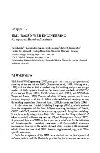
Figure 1. Control Engineer Interacting with the ESS The initial idea was that our tool should integrate and interact with a general purpose CASE tool in order to ease the process of designing the Function Block diagrams. This would enable the potential engineer to analyse his industrial application, write requirements and draw scenarios and class diagrams with the CASE tool. In a subsequent step, he could obtain automatically the diagrams of the CASE tool to our prototype tool, and proceed with the design of his application with Function Blocks, which are closer to the final implementation. Figure 1 show this concept, where the engineer interacts with the general purpose CASE tool and the ESS extension tool during the process of engineering his IPMCS application.
4.1 Selecting a general purpose CASE tool As we presented above, our implementation needed a CASE tool that could interact with our FB design tool, thus it should have at least one extension mechanism. We examined several CASE tools and fortunately Rational's Rose, one of the most popular CASE tools, has several extension mechanisms, and comes with a suite of specific tools for software engineering, to cover the needs from requirements capture through the final implementation. Rose supports two mechanisms and can be extended either with its custom scripting language, or can be used as a COM automation server [11] through a type library provided by Rational. At this stage, we considered these two possible available solutions for the integration: either to extent Rose through its scripting language with a set of new menu commands, toolbar buttons, etc, or to use an external custom developed tool for the management of the Function Block diagrams by means of the automation mechanism of the CASE tool. We chose the second option, since it was simpler and much more manageable to use the automation interface and additionally we could implement more rapidly the Function Block prototype tool. The automation interfaces makes possible to externally browse the internal object model of Rose, i.e. its classes, properties and diagrams. Additionally, it lets the programmer to manage (create, edit, delete) externally, classes and diagrams, thus giving the possibility to enable in our extension tool roundtrip engineering capabilities.
4.2 Our prototype tool: Implementation details
FB design tool
CASE tool ESS tool
Engineer
Figure 2, shows a screenshot from our prototype FB design tool, which we developed with Borland's Delphi IDE. Rose allows us to use it as a COM server, through its type library as mentioned. Type libraries provide a way to get more type information about an object than can be determined from an object’s interface. The type information contained in type libraries provides needed information about objects and their interfaces, such as what interfaces exist on what objects, what member functions exist on each interface, and what arguments those functions require.
So, the first step was to import the type library in Delphi and have access to the interface of Rose automation. Delphi provides a type library editor and a tool that translates the type library file to Delphi constructs and creates the equivalent dispatch interfaces. Dispatch interface declarations are used to describe the methods and properties a COM Automation object implements through its IDispatch interface.
which (through windows API) creates the instance of the CoClass and thus the application. An example is the following extract from the code (in Delphi): fRoseApp:= CoRoseApplication.Create; where fRoseApp variable is an instance of the IRoseApplication interface and is used as the interface to Rose. Then we can load our model with theModel:= fRoseApp.OpenModel('C:\test\class_diagram_01.mdl'); and get for example from the diagram categories, the Scenario Diagrams with theRC := theModel.RootCategory ; theSD := theRC.ScenarioDiagrams; where theRC is type of IRoseCategory and theSD is type of IroseScenarioDiagram Collection
Figure 2. Our prototype FB design tool
After importing the type library, we have full access through our programming language to all the interfaces and Rose 's object model.
Other useful interfaces are IRoseObjectInstance which provides access to all object instances on a diagram, IRoseMessageCollection which provides access to the collection of messages in a scenario diagram and the IRoseMessage which provides access to individual messages. Figure 3 shows Rose with our project opened, which normally is active and hidden in the background. Figure 4 shows on the left-hand side the class ValveControl with some methods like check(), ProgramReady() and OpenValve() as it appears in the CASE tool. The right–hand side, shows the equivalent Function Block that is created from the FB prototype tool when it applies our proposed transformation rules. The event inputs and outputs of the Function Block, have been designed automatically. For example the output events SBW() and PUR() on the Function Block, are extracted from the message exchange of the objects on an interaction diagram while a use case is realized. ValveControl check() ProgramReady () openValv e()
Figure 4. Class to Function Block
4.3 Portability in ESSs
Figure 3. Rose running on the background
We decided for our tool to comply with the portability agreement proposed in IEC 61499 Industry Technical Agreement. So our tool should be capable of: •
The first step is actually to create the application, so we invoke a certain call to class factory's CreateInstance method,
producing library elements like data types, function block types, resource types, device types, function block diagrams, system configurations, etc using the syntax and the semantics defined in Annex A of IEC 61499-2
•
•
correctly parsing and interpreting all elements in the XML DTDs, which are defined in Annex A of IEC 61499-2 utilizing files for the exchange of library elements. For example the tool should support certain file types for element exchange like .fbt for Function Block types, .dev for Device types, e.t.c.
The above requirements, guided us to include in our tool XML parsing and streaming capabilities. With the above provided interfaces, the tool is capable to browse in the diagrams and in their objects and apply the rules. In order to check the portability of our tool, we have managed to exchange library elements such us Function Block types and diagrams, with the FBDK tool mentioned previously. Additionally, FBDK gives us the ability to test via the Java library that it provides, our Function Block design diagrams.
References 1. IEC Technical Committee TC65/WG6, “IEC61499 Industrial-Process Measurement and Control – Specification”, IEC Draft 2000 2. IEC sub committee no. 65c: digital communications, working group 7: function blocks for process control, “IEC1804 General Requirements”, IEC Draft 1999 3. C.Cseh, M.Jansen, J.Jasperneite, “ATM networks for factory communication”, 7th IEEE International Conference on ETFA, 1999 4. K.Thramboulidis, C.Tranoris , “An Architecture for the Development of Function Block Oriented Engineering Support Systems”, IEEE International Symposium on CIRA July 29 - August 1, 2001, Banff, Alberta, Canada 5. Ivar Jacobson et.al. “The Unified Software Development Process”, Addison, Wesley 2000 Ch.2 p.26
5. Conclusions In order to enhance the requirements capturing, the system analysis and the transition to the design phase of IPMCSs, we have defined a new approach towards a unified design methodology. Our approach adopts use cases and the UML notation to capture requirements of the IPMCS applications. It uses, the interaction diagrams for the first realization of use cases and a set of well-defined transformation rules for the subsequent evolution of requirements to Function Block Diagrams. In this paper we have presented such a prototype FB design tool and additionally its interaction with a popular generalpurpose CASE tool. Our FB tool is capable of communicating with the CASE tool and it can follow specific transformation rules, for mapping interaction and class diagrams to equivalent function block diagrams. Through our process the engineer designs his diagrams on the CASE tool and exports them to our prototype FB design tool and vice-versa. Then he proceeds with the design of his application with Function Blocks, which are closer to the final implementation. We have presented also implementation details of our tool and how it complies with the IEC 61499 Industry Technical Agreement. In our prototype tool still some missing functionality exist and further improvement is needed. The tool needs: •
the capability of distributing the Function Blocks in field devices over interconnected networks
•
the ability to download the Function Block types and Function Blocks networks to the interworking units of the networks and create all the Function Block data and event connections
•
a more sophisticated user interface for the engineer to design the Function Block diagrams
•
further operations that will help the engineer towards the round-trip process.
6. R. Lewis, Modelling control systems using IEC 61499, IEE 2001 7. Kruchten P.: “The 4+1 view model of architecture”, IEEE Software, Nov. 1995 8. OMG UML specification version 1.3, March 2000 9. C. Tranoris, K. Thramboulidis, "From Requirements to Function Block Diagrams: A new Approach for the Design of Industrial Applications", 10th Mediterranean Conference on Control and Automation, 9-12 July, 2002 10. “Function Block Development Kit”, Automation, http://www.holobloc.com
Rockwell
11. http://www.microsoft.com/com/tech/dcom.asp 12. K. Thramboulidis, “Development of Distributed Industrial Control Applications: The CORFU Framework”, 4th IEEE International Workshop on Factory Communication Systems, Sweden, August 2002