TUCS Technical Report No 519 ... 7.2 Object Diagram to Data-flow diagram transformation script . . . . 28 .... way that the process provide support for automation.
Tool support for DFD to UML model-based transformations Dragos Truscan Jo˜ao M. Fernandes Johan Lilius
Turku Centre for Computer Science TUCS Technical Report No 519 April 2003 ISBN 952-12-1148-2 ISSN 1239-1891
Abstract We present an approach to combine both the data-flow and object-oriented computing paradigms to model embedded systems. The rationale behind the approach is that both views are important for modelling purposes in embedded systems environments, and thus a combined and integrated usage is not only useful, but also fundamental for developing complex systems. We exemplify our approach using an IPv6 router case study. We also show how we have automated the transformations between views.
Keywords: embedded systems design, UML, DFD, design flow, model transformations, internet protocol version 6, IPv6 routing, transport triggered architecture
TUCS Laboratory Embedded Systems Laboratory
Contents 1
Introduction
1
2
Related work
2
3
An UML-DFD Design Flow 3.1 IPv6 Router Requirements . . . . . . . . . . . . . . . . . . 3.2 Capturing the requirements into Use Cases . . . . . . . . . . 3.3 From the Use Case Diagram to the Initial Object Diagram . . 3.4 Refactoring the Initial Object Diagram . . . . . . . . . . . . 3.5 From Object Diagram To DFD . . . . . . . . . . . . . . . . 3.5.1 Creating the DFD . . . . . . . . . . . . . . . . . . . 3.5.2 Building the Data Dictionary . . . . . . . . . . . . . 3.6 Using Activity Diagrams to specify internal behavior of DFD 3.7 From DFD to object-oriented diagrams . . . . . . . . . . . . 3.7.1 From DFD to object-based class diagram . . . . . . 3.7.2 From DFD to class diagram . . . . . . . . . . . . .
. . . . . . . . . . .
4 5 6 7 9 10 10 12 13 14 14 17
4
The SMW Tool 4.1 UML1.4 and SA/RT profiles . . . . . . . . . . . . . . . . . . . . 4.2 Scripting and transformation scripts . . . . . . . . . . . . . . . .
20 20 21
5
Conclusions
21
6
Acknowledgements
23
7
Appendix 7.1 Use Cases Diagram to Initial Object Diagram transformation script 7.2 Object Diagram to Data-flow diagram transformation script . . . . 7.3 Data-Flow Diagram to Object-Like class diagram transformation script . . . . . . . . . . . . . . . . . . . . . . . . . . . . . . . . 7.4 Data-Flow Diagram to Class Diagram transformation script . . . .
27 27 28
. . . . . . . . . . .
. . . . . . . . . . .
29 32
1
Introduction
In this report we show our approach in combining the object-oriented and DFD views for the analysis and design of embedded systems and our use of automated scripts to speed up the design process by implementing transformations between the views. The approach consists of specifying the system following a functional decomposition and representing it using the benefits of both object-oriented and DFD views. Some of the ideas presented here were already analyzed and discussed in [24], but with a different perspective. There, the main objective was the definition of a complete UML-based design flow (or methodology) for embedded systems, making special emphasis on applying object-oriented techniques to the specification and design of a protocol processor. In this case study we had in many situations the feeling that there was a functional and structural view of the system that was not adequately represented by the diagrams provided in UML. A second motivator for this work has been the experience of the 3rd author, that at least in the Turku, Finland region, the embedded systems industry is reluctant to move from structured to object-oriented methods. There is therefore a need for studying the interrelation between structured and object oriented methods. Setting up a framework for comparing analysis techniques and producing useful conclusions is not an easy task. This may be the reason why there is not yet a definite proof that shows that the object-oriented paradigm is definitely better than structured methods [17], and some authors even suggest the opposite [28]. In fact, attempts to prove formally that one approach is better than another are seldom effective, in any domain. This is extremely harder in information technologies, because in real-world scenarios, there is hardly ever an opportunity to develop the same system in two different ways and compare them. If a careful comparison is undertaken, one can see that object-oriented and structured methods do not differ so much on the meta-models they use. For example, the set of diagrams suggested by the Object Modeling Technique (OMT) methodology [35] is surprisingly close to the traditional proposals of Structured Analysis [19]. In our opinion, there is not too much surprise in this fact, since object-orientation can, in an historical perspective, be seen as an evolution (and not a revolution) of the structured methods. In fact, object-oriented and structured methods both recognize the need to use three models to specify a complex software system: a functional model, a control model and a data model [38]. For example, the usage of statecharts was proposed in both approaches with apparent successful results [10]. Probably, the major discrepancy between structured and object-oriented analysis relies on the way those three models are used, that is, the order in which they are created. Object-oriented methods have the class diagram (a data-oriented model) as its main modeling tool, while structured methods use data flow dia1
grams, an activity-oriented model, as its principal diagram. The popularity of object-orientation is probably due to the observable emphasis on data in system design that has increased considerably in the last years [23]. Despite these similarities, it is unfortunate that a culture of rivalry seems to exist in the software community with respect to these two paradigms. Nowadays, the convention is to use either a pure object-oriented approach or a pure structured approach. We prefer to view the two approaches as complementary, each one with its own strengths and weaknesses. We think that a proper mixture of the approaches is possible, so that the best of both worlds can be offered. There were several attempts to combine these two approaches [6] [7] [21] [32] [36] [39] , but none of them is widely known or used. Although some recognized researchers [11] [40] argue that object-oriented analysis and structured analysis are fundamentally incompatible, we believe that the topic deserves more research effort in order to understand if the integration can be effectively achieved and, if a positive answer is obtained, how that can be accomplished. This paper intends to contribute to that effort. The main contributions of this paper are: (a) an approach that integrates dataflow and object-oriented views for specification of embedded systems, (b) a set of transformations for moving from the data flow view to the object-oriented one and (c) the implementation of these transformations using automated scripts. We use a simplified IPv6 router case study to illustrate the approach. Following we discuss, in Section 2, about the related work on integration of DFD and object-orientation. In Section 3 we introduce our approach and propose a design flow for embedded systems specification. We present each phase of the design flow and show how we perform transformations between structured and object-oriented views of the specification and the main steps to be taken in order to provide an automatable approach. In Section 4, we briefly introduce the SMW tool that we used to support the views and also to implement the transformations. The paper ends with some conclusions and comments about our approach. To exemplify how the transformations were implemented, several Python scripts are are given as example in the Appendix.
2
Related work
Many authors have already studied the combination of DFDs with object-oriented methods. A theoretic survey of this topic is given in [15]. Here we only discuss some approaches that we feel are most relevant to the present work. Within the Object-Process Methodology (OPM), the combined usage of objects and processes is recommended [12]. An Object-Process Diagram (OPD) can include both processes and objects, which are viewed as complementary entities 2
that together describe the structure and behavior of the system. Objects are persistent entities and processes transform the objects by generating, consuming or affecting them. In addition, states are also integrated in OPDs to describe the objects. The usage of OPM, for modeling, specifying, and designing reactive and real-time systems, was also proposed, by extending the notation with notions such as timing constraints, events, conditions, exceptions, and control flow constructs [31]. In [32], the DFD notation is modified and the roles of the functional models are redefined, in order to use DFDs while retaining the spirit of object-orientation. Two types of functional models are suggested: Object Functional Models (OFM) and Service Refinement Functional Models (SRFM). OFMs are used to model the services provided by individual objects, while SFRMs model how the services of individual objects can be composed to implement the services of their corresponding aggregation object. In both models, the only modeling elements are: objects, processes and data-flows. The data store is not necessary, according to the authors, since they use an object for that purpose. The interactions with a data store are modeled as communications with the corresponding object. In another proposal [8], the functionality associated with each use case is described as an E-DFD (an extended version of the traditional DFD). A tool, called SysObj, uses these inputs to automatically generate an object model, that is viewed as the architecture of the system. This method is also related to an integrated environment for developing distributed systems with the object-oriented paradigm [5]. In the Object Modeling Technique OMT, DFDs are also used to describe the functional model of a system [35]. Since in OMT the system is also specified by two other models (the object and the dynamic models), DFDs specify the meaning of the operations in the object model and the actions in the dynamic model. Although there is some attempt at integration, this correspondence is left completely vague and can not be analyzed in any useful way. For reverse engineering purposes, the adoption of reverse generated DFDs (i.e., DFDs obtained after interpreting the source code) is proposed as the basis to obtain the objects that a system is composed of [16]. The approach is said to be hybrid, because it is not fully automatic, requiring in specific occasions the assistance of a human expert with knowledge of the domain. Again in a reverse engineering context, it is suggested the combined usage of DFDs and ERDs to describe the system being modernized [20]. Alabiso also proposes the transformation of DFDs into objects [6]. In order to accomplish the transformation, he proposes the following four activities: (1) Interpret Data, Data Processes, Data Stores and External Entities in terms of objectoriented concepts; (2) Interpret the DFD hierarchy in terms of object decomposition; (3) Interpret the meaning of Control Processes for the object-oriented model; (4) Use data decomposition to guide the definition of the object decomposition. 3
Another interesting proposal is the Functional and Object-Oriented Methodology (FOOM) [36], which is specifically tailored for information systems. The main idea behind FOOM is to use the functional approach, at the analysis phase, to define users requirements and the object-oriented approach, at the design phase, to specify the structure and behavior of the system. In the FOOM, the specification of user requirements is accomplished, in functional terms, by OO-DFDs (a DFD with data stores replaced by classes), and in data terms by an initial objectoriented schema, or an ERD which is easily transformed into an initial objectoriented schema. In the design phase, the artifacts from the analysis are used and a detailed object-oriented and a behavior schemas are created. These schemas are the input to the implementation phase, where an object-oriented programming language is adopted to create a solution for the system at hand.
3
An UML-DFD Design Flow
In our design flow we integrate and combine the object-oriented and data flow views for the analysis and design of embedded systems. The approach consists of specifying the system following a functional decomposition and of representing the system using the benefits of both object-oriented and DFD views, in such a way that the process provide support for automation. The main phases of the design-flow (Figure 1) are: a. Extract Application Requirements b. Create the Use Case Diagram (UCD) c. Specify each Use Case in a textual manner d. Transform the UCD into an IOD e. Refactor IOD by grouping, splitting and discarding objects based on their functionality f. Transform the IOD into a DFD g. Identify Data Flows and build a Data Dictionary h. Specify process behavior using Activity Diagrams i. Transform the DFD into an Object Diagram (OD) or j. Transform the DFD view into a Class Diagram (CD) 4
a. Extract Application Requirements
Requirement List
b. Create Use Case Diagram
c. Specify Use Cases
Use Case Description
Use Case Diagram
d. Create Initial Object Diagram
e. Refactor Initial Object Diagram
Initial Object Diagram refinement
f. Create Data Flow Diagram
Data Flow Diagram h. Create Activity Diagrams
g. Build Data Dictionary
Activity Diagrams
Data Dictionary
i. Create DFD-like Object Diagram
j. Create Class Diagram
Object Diagram
Class Diagram
Figure 1: Integration of UML and DFD paradigms During the design flow we have to change several times the view of the system to be able to work on specific details provided by each view. To facilitate the changing, we have implemented transformations that automate the transition between the steps.
3.1
IPv6 Router Requirements
We have tried our method on the design of an IPv6 router. IPv6 (Internet Protocol version 6) [27] is the latest version of the Internet protocol introduced to overcome the address restrictions of IPv4. It features 128-bit addresses (compared with 32-bit addresses for IPv4) and improved addressing hierarchy. Additionally, the structure of the IPv6 datagrams has been simplified by introducing an extensible 5
datagram format consisting of a header and optional extension headers. An IPv6 router is a network device that deals with transferring data from one network to another in order to reach its final destination. Two main functionalities have to be supported: forwarding and routing. Forwarding is the process of determining on which interface of the router a datagram has to be sent on its way to destination, while routing is the process of building and maintaining a table (routing table) that contains information about the topology of the network. Different routing protocols exist. We have selected for our implementation the Routing Information Protocol Next Generation (RIPng) [26] which is an UDPbased protocol. UDP (User Datagram Protocol) is a connectionless protocol specified in [34]. The router builds up the Routing Table by exchanging information with neighboring routers. At regular intervals, the routing table information of a router is broadcasted to the adjacent routers to inform them about changes in topology. Following, the term datagram refers to a package of data transmitted over a connectionless network. Connectionless means that no data connection has been established between source and destination.
3.2
Capturing the requirements into Use Cases
We start by analyzing the specification of the router requirements and building a Use Case diagram. We identify two external actors that interact with the router. The Node is a common network node that requests the router to forward datagrams and eventually to send back an ICMPv6 error message in case of failure. The Router represents the neighboring routers that exchange topological information with our router. Then, we identify the services that the system has to provide to the external environment and extract them into a list of use cases. We have identified 6 use cases that provide services to the external actors. Each use case is accompanied by a short textual description that specifies its functionality. The use case diagram is given in Figure 2. Previously we have tried different approaches in specifying the external actors and the use cases of the IPv6 router [15, 25]. In the present example we assume that the datagrams exchanged between the router and the environment are of three types (Forwarding, Routing and Error), and that their classification is done outside the system (i.e. the datagram is already correctly classified when entering the IPv6 router). From the written specification of the IPv6 router we have extracted the following use cases: 1. Forward Datagram - The router receives a datagram from a node on one of its interfaces and decides on what interface(s) the datagram should be sent in order to reach its final destination. Upon receiving, the datagram is checked 6
for validity and correct addressing, and if not correct the ICMPv6 subprotocol is invoked to send an Error Message to the originator of the message. In order to decide the next interface, the router interrogates its Routing Table for the next route. If no route is found the ICMPv6 subprotocol is invoked to send an Error Message back to the originator of the datagram. 2. Send Error - If during the processing of a datagram an error is encountered or a forwarding route for a datagram is not found, an ICMPv6 Error Message is sent back to the originator. 3. Treat Request - The router receives Request datagrams (from adjacent routers on the network) that request topological information from the Routing Table. Upon receiving, the datagrams are checked for validity and correctness of the fields. If a datagram is not correct the ICMPv6 subprotocol is invoked to send an Error message back to the originator. 4. Inform Topology - The information stored in the Routing Table is sent to adjacent routers to inform about changes in topological information. The information is sent either periodically as multicast datagrams to all adjacent routers or as result of a special request from a single router. 5. Update Routing Table - The router receives Response datagrams from adjacent routers in order to update its Routing Table information. Upon receiving, the datagrams are checked for validity and correctness of the fields. If a datagram is not correct the ICMPv6 subprotocol is invoked to send an Error message back to the originator. 6. Create Request - Whenever the Routing Table of the router is empty a Request message is sent on each interface to all adjacent routers (as a multicast datagram) to request topological information. Using use cases does not necessarily imply that subsequently an object-oriented approach must be followed. Use cases represent a technique that is quite independent of object-oriented modeling and can be applied to any system, developed either with a structured or object-oriented approach. Indeed, in the next subsections we will show how we obtain a data flow diagram starting from use case diagram.
3.3
From the Use Case Diagram to the Initial Object Diagram
From the Use Case Diagram we identify the initial set of objects in the system by decomposing each use case into three objects: control, data and interface objects, 7
IPv6 router
{3.} Treat Request
{1.} Forward Datagram node
{4.} Inform Topology
{2.} Send Error
{5.} Update R'ting Table
router
{6.} Create Request
Figure 2: IPv6 Router Use Case Diagram based on the approach presented in [14]. The objects have the same number as the initial use case, but each of them has the appropriate tag name. For instance, the {1.i}, {1.c} and {1.d} objects (Figure 3) represent the interface, control and data objects obtained from splitting the Forward Datagram {1.} use case. Also, a corresponding actor is created in the initial object diagram corresponding to the actors in the Use Case Diagram. Finally, we add associations between objects and also between objects and the external environment (actors). We enforce a clear separation of the functionality that each object category has inside the system. Control objects deal only with algorithmic and control behavior. Interface objects are only placed at the border of the system to intermediate between the internal and external communication of the system. Data objects deal only with storing data and providing access methods to this data. When a system is divided into parts, both structure and behavior are being decomposed along with functionality. Some authors [22] even consider that all systems are submitted to functional decomposition even when different decomposition paradigms are used. Usually the designer is focusing his effort only on one view during decomposition but we consider that the other aspects are always present as side-effects. The main steps of transforming the Use Case Diagram (UCD) into a an Initial Object Diagram (IOD) are: 1. each Actor in UCD is transformed into an Actor (instance) in IOD 2. for each Use Case in UCD, three objects (interface, control, data) are created in the IOD 8
node forwarding datagram
node error datagram
router
router
request datagram
router
response datagram
response datagram
router request datagram
{1.i}
{2.i}
{3.i}
{4.i}
{5.i}
{6.i}
{1.c}
{2.c}
{3.c}
{4.c}
{5.c}
{6.c}
{1.d}
{2.d}
{3.d}
{4.d}
{5.d}
{6.d}
Figure 3: The Initial (Refactored) Object Diagram 3. in the IOD, an association is drawn between the interface and control objects belonging to the same use case 4. similarly an association is drawn between control and data objects belonging to the same use case 5. for each Actor-UseCase association in the UCD, an association is drawn between the corresponding Actor and the interface object generated by the given Use Case The detailed transformation script is presented in the Appendix, subsection 7.1.
3.4
Refactoring the Initial Object Diagram
According to the 4SRS method [14], by instantiating scenarios for the initial use cases we decide what objects are kept or disposed of, and also we identify the communication (depicted by association) among objects. The remaining set of objects is refactored, by decomposing or grouping together objects of the same type. The interface objects that are communicating the same information with the same actor and in the same direction can be grouped together (for instance {5.i} and {3.i} both receive routing datagrams, either request or response datagram, from the router). An interface object that communicates bidirectionally with one node, can be split into 2 interface objects ({1a.i} and {1b.i}), one dealing with incoming traffic and the other with the outgoing traffic. We structure the model so 9
that all communication between data objects and interface objects is done through control objects. The final result of the refactoring is presented in Figure. 3. Although, the splitting and grouping of objects are supported by scripts, the refactoring process is performed manually based entirely on the designer’s experience. Future research will look into a more automated approach based on identification of patterns.
3.5
From Object Diagram To DFD
Sometimes designers need to be able to change the view they are using. We use the DFD view to be able to identify, classify and refine the data flows involved in the system. DFDs use four symbols to represent any system at different levels of detail. The four modeling concepts to be represented are: data flows (movement of data in the system), data stores (repositories for data that is not moving), processes (transformation of incoming data flows into outgoing data flows), and external entities (sources or destinations outside the system boundary). They provide a datadriven view of the system useful for describing transformational systems, such as digital signal-processing systems, compilers, multimedia systems, or telecommunication devices. 3.5.1
Creating the DFD
We obtain the data flow model of the system from the refined set of objects (Figure 3), by noting the direction of the communication among the objects and then defining data entities that are being exchanged. Thus, to obtain the data-flow diagram of the system two steps are required: to specify the processes (data transformations) and data stores in the system, and then to identify the data flows involved. The first step of the transformation process is straight-forward because of the way the initial object diagram was structured. In the initial object diagram we have control objects and interface objects that are processing input communication from neighboring objects and transforming it into output communication. This is similar with the behavior of the processes provided by the DFD concept. This fact allows us to transform all the control and interface objects into DFD-specific processes (data transformation). Similarly, data objects in the initial object diagram are transformed into data store elements in DFDs. Most of the DFD approaches in literature, do not make a clear distinction among processes with respect to their execution in time. Our opinion is that we can observe two types of behavior: processes that start their execution when one of its input flows becomes active, and processes that execute continuously, independent of their input flows status. We name them reactive processes and active 10
Foward Datagram
Routing Datagram
{1a.i} ReceiveFwd
{3.i+5.i} Receive Routing RequestDatagram+ RecvInterface
FowardDatagram+ RecvInterface
{1a.c} Validate
ResponseDatagram+ RecvInterface
RequestDatagram+ RecvInterface+ ErrorType
FowardDatagram+ RecvInterface+ ErrorType
{3.c} Request
{2.c} ICMP
{5.c} Response
ResponseDatagram+ RecvInterface+ ErrorType
FowardDatagram+ RecvInterface
RTEs
Trigger Response {1.d} dataStore
FowardDatagram+ RecvInterface
{1b.c} Forward
{5.d} Routing Table
RTEs
RTE# ErrorDatagram+ RecvInterface {4.c} Create Response
ForwarddDatagram+ RecvInterface+ ErrorType
RTEs
{6.c} Create Request
ResponseDatagram+ Interface(s) FowardDatagram+ FwdInterface RequestDatagram+ Interface(s) {1b.i} SendForward
{2.i} SendICMP
{4.i+6.i} SendRouting
Foward Datagram
Error Datagram
Routing Datagram
Figure 4: The Data-Flow Diagram of the Router processes, respectively. A process is considered to be active if it has no input flows from other processes or its behavior is self-triggered (output flows are fired without an input flow triggering the process). One example of active processes would be a process that is periodically reading a data store (Figure 4, processes {1b.c} and {6.c}). Here, the input flows are triggered by the processes themselves and not by the data stores, despite the fact that there is a data-flow from the data stores to the given processes. Classifying processes into active and reactive helps 11
the designer in the next design phases to specify the internal behavior of each process. To transform an IOD into a DFD the following steps must be performed: 1. transform each Actor in the IOD into an External Entity 2. transform interface and control objects into Data Transformations in the DFD 3. transform data objects into Data Stores 4. associations between elements of the IOD are transformed into Data Flows either between external entities and data transformations, or between data transformations and data stores, or in-between data transformations 5. we identify and mark active processes in the DFD The detailed transformation script is presented in the Appendix, subsection 7.2 In the second step, the associations among the initial objects are transformed into input and output data flows in DFD based on the system specification. During the refinement of data flows, we focus on adding new details about the data entities and types transported over the flows. The resulting diagram is presented in Figure 4. 3.5.2
Building the Data Dictionary
A classification of the data flows involved in the system is performed by building a Data Dictionary. This is done by analyzing the data that is moved between data transformations and having as primary information source the application requirements. The data flow identification is performed manually and it is based on designer’s experience. A complete Data Dictionary specification of the IPv6 Router under study can be found in [15]. Following we only present a small example, where the datagram types transported through the system (Router) are classified. Datagram = ForwardDatagram | RoutingDatagram | ErrorDatagram ForwardDatagram = IPv6Header + Payload RoutingDatagram = IPv6Header + UDPHeader + RIPMessage ErrorDatagram = IPv6Header + ICMPv6Message
12
3.6
Using Activity Diagrams to specify internal behavior of DFD
There is no strict requirement in the literature on how the data transformations’ behavior is specified. Typically it is done using pseudocode or statecharts. Since we were addressing a graphical approach we described the processes inside the data-flow diagram using the Activity Diagrams of UML. The reasons for choosing this approach are: • there is a certain amount of similarity among activity diagrams and pseudocode. The similarity is in the sense that both have processes (or activities) as a fundamental concept. But DFDs exchange data, while Activity Diagrams exchange control. • they allow decomposing of the activity states into other activity diagrams or grouping many activity states into more complex ones, thus making easier for the designer to work at different levels of detail of the design. • using activity diagrams instead of state machines makes easier the re-factoring process by splitting and joining two different activity diagrams, which is far from trivial when using state machines. • we are addressing the area of protocol processing, which requires dataintensive and algorithmic control-flow An activity diagram is a set of actions implementing atomic computations that result in a change of the system’s state. Each activity is triggered by a transition and executes until completion. UML does not prescribe a specific language for describing activities, allowing by this a great deal of flexibility for designer. Another important feature of Activity diagrams is the possibility of hierarchically decomposing the activities into subactivities (subActivity Diagrams). This allows the designer to refine the initial Activity Diagram into a more detailed specification. There exists two types of activities inside a diagram: action states and activity states. Action states are executable atomic operations that cannot be further decomposed, while an activity state can be represented by another Activity Diagram containing both action states and activity states, or action states only. Additionally, activity diagrams provide mechanism for sending and waiting for messages and for synchronization of control flows (join and fork). More details on activity diagrams can be found in [9, 13]. In our design, we build an Activity Diagram for each Data Transformation, in which all the activities are activity states in the beginning. Each activity is described in a natural language. Activity diagrams receive and send events to their neighboring environment. The events should correspond to the Data Flows already existent in the DFD. Activity states are then decomposed into other activity 13
diagrams which contain smaller parts of the system’s functionality but at a higher level of detail. This process can take many iterations until transforming all the activity states into action states. We consider that an activity can be called an action state when it is directly implementable on the target platform, either in hardware or in software.
3.7
From DFD to object-oriented diagrams
One specific situation where the usage of DFDs is helpful is in re-engineering activities where the system was previously developed following the guidelines of some structured method. Even if the diagrams are no longer available, it is expected to be easier to reverse-engineer the program code into DFDs and other complementary models, than to transform it directly into some object-oriented models. For obtaining a object-oriented model of the system starting from the DFDmodel we have tried 2 approaches. In the first approach we transform the DFD model directly into an object diagram by transforming on an one-to-one basis the processes and data stores in the DFD model into objects. The second approach follows a more object-oriented view where we focus on classifying data in the system and detecting class methods that operate over that data. Some similar ideas were already proposed in the FOOM methodology [36] for developing information systems, but its usage for embedded systems requires necessarily some adaptation. The transformation of a functional specification in Z into an object-oriented one in Object-Z, for re-engineering purposes, is also proposed in [32]. 3.7.1
From DFD to object-based class diagram
In the first approach, we map the DFD model directly into an DFD-like object diagam, by transforming the artifacts in the DFD model on a one-to-one basis. Basically, the algorithm consists in transforming each data transformation in the DFD into an object in the Object Diagram, and the data flows between the data transformations into associations. In addition, the data flows involved in the system become internal attributes of the classes (objects), are encapsulated into the objects and used now to describe the internal state of the objects. In order to access the data entities inside objects, corresponding methods are added. For instance, the initial ForwardDatagram data flow between ReceiveFwd and Validate processes in Figure 4, has been encapsulated inside the Validate object, and is only modified by checkLength() method, while its value is dispatched to the adjacent objects through store() and sendFwdError() methods. Objects originating from processes placed at the border of the system will have set() methods to communicate with the external environment, while the other 14
{1a.i} receiveForward «methods» setFwdDatagram()
{3.i+5.i} receiveRouting «methods» setRequest( ) setResponse( )
sendFwdDatagram()
check()
{1a.c} validate
check()
{3.c} Request
«methods» sendFwdDatagram( ) sendFwdError()
{5.c} Response
«methods»
«methods»
sendRequestDatagram()
sendResponseDatagram()
sendFwdError() store()
writeFwdDatagram() sendRoutError()
{1.d} dataStore
{2.c} ICMP
«methods»
{5.d} routingTable
setTrigger()
«methods»
readFwdDatagram(,) writeFwdDatagram(,)
«methods»
sendFwdError() sendRoutError()
writeRTE() readRTE()
readRTE()
readFwdDatagram()
{1b.c} Forward
readRTE()
sendRoutError()
{4.c} CreateResponse
«methods» sendErrorDatagram() send()
«methods» sendFwdDatagram()
{6.c} CreateRequest
«methods»
run( )
{1b.i} sendForward
writeRTE()
«methods»
run() setTrigger()
run()
sendResponseDatagram()
{2.i} sendICMP
sendRequestDatagram()
{4.i+6.i} sendRouting
«methods»
«methods»
sendErrorDatagram()
sendResponseDatagram() sendRequestDatagram()
Figure 5: The DFD-like Class Diagram processes will have send() methods that receive as parameters the input data flows in the DFD. Objects obtained from active processes will have in addition a run() method specifying their state machine, while the objects originating from Data Stores receive write() and/or read() methods to provide access to their data, based on the data flows accessing them. One should note that the way the elements in the object diagram are named, is only to help in automating the process. Once the transformation process is completed, the names of different elements can be changed to be more suggestive for the designer. Caution has to be taken that by changing names, the consistency of the design is not affected. Thus, either the modelling tool or the design method should provide support to check the consistency of the design after each transformation step. After the transformation is completed, we focus on specifying the behavior 15
of each object. In fact, defining the behavioral aspects of the system is the main purpose of this view. The final object model (Figure 5) is very similar to the DFD one, but now we have objects that have an internal behavior and provide services (implemented by methods) to the adjacent objects. The newly created objects are also classified as being active or reactive based on the processes from which they were generated. The difference between them is that the reactive objects execution is triggered only when one of their methods is invoked, while the active objects have a state machine (usually implemented by a run() method) executing continuously. The transformation script performs the following steps: 1. each data transformation in the DFD is transformed into a new class/object in the object model 2. transform flows between transformations in DFD into class associations 3. the classes originating from processes receive input flows receive set () method and a corresponding attribute 4. active objects receive run() method 5. objects receiving an input data-flow receive send () method of the incoming dataflow 6. each data store is transformed into a class/object, with read and write methods, according with the input/output direction of the flows connected to the data store The detailed transformation script is presented in the Appendix, Section 7.3. The object diagram in Figure 5 provides a low level of abstraction and data encapsulation, but it proved to be quite suited for prototyping purposes and functional testing of the specification. Additionally, it is a good candidate for being mapped onto a hardware-based platform, because its granularity is at a relatively low level of detail. We used this approach to design protocol processing applications targeted to our TACO processor platform [24]. The TACO protocol processor is based on the Transport Triggered Architecture (TTA) [10]. In TTA processors data transports are programmed and they trigger operations - traditionally operations are programmed and they trigger transports. A TTA processor is composed of functional units (FUs) that communicate via an interconnection network of data buses. The processor is programmed using one type of operation only, the move operation, that specifies data transports on the interconnection network. An operation of the processor occurs as a side-effect of the transports between functional units. 16
Each transport has a source, a destination and data to carry from one unit to another. The resources of the processor are specified and implemented in a library of components using the SystemC language [3]. SystemC is an object oriented (extension of C++) hardware specification language where the hardware modules are instances of SystemC classes. Due to the architectural aspects of the processor a DFD-like approach proved well suited for the specification and design phases. Objects in Figure 5 naturally map to FUs and the methods of the objects have similar granularity with the operations provided by the TACO processor. To configure TACO to support a given application one has to select a number of required resources from the component library (modeled as SystemC class diagram). The selection is done by analyzing the object diagram of the of the specification and selecting from the SystemC class diagram those resource supporting operations. Thus, being able to go from a structural representation to an object oriented one at any point during the design flow proved to be helpful. 3.7.2
From DFD to class diagram
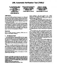
In the second approach to create an object-oriented model of the system, we take a view where data involved in the system plays a central role. This approach is not far from the structured methods philosophy where determining the type of data involved in the system is the main task. The transformation between the views is based on the classification and encapsulation of data into classes, along with the corresponding methods that operate over this data. Briefly, the algorithm implemented by the transformation script classifies all the data flows and data stores inside the DFD, based on their type. For each identified type in the DFD, a corresponding class is created in the class diagram. In order to add class methods, the script looks for three kinds of patterns in the data flow diagram: data flows communicating with the external environment of the system (Figure 6), data flows between two processes (Figure 7) and data flows that communicate with data store elements (Figure 8). A number of processes (data transformations) operate over each data flow class inside the DFD. For instance, the ForwardDatagram data flow (Figure 4) is processed by different data transformations (ReceiveFwd, Validate, Forward, SendForward, ICMP). Thus, we create the forwardDatagram class inside the class diagram (Figure 9) and we add the DFD processes that affects it as methods of this class. We consider that a process becomes a method of a class only if it has as output flow the data flow type represented by that class. For instance, the ICMP process in Figure 4 is not transformed into a method of forwardDatagram because it outputs an ErrorDatagram. The Data Store elements in the DFD receive a special treatment. Since they are 17
y Attribute:
x
y
dataTrans
Operation: receive_x()
Actor
Actor
Figure 6: Border process pattern x
dataTrans1
x
y+p1
z
dataTrans2
y y.dataTrans1(x)
Attribute: Operation:
Attribute:
z z.dataTrans2(y,p1)
Operation: dataTrans1(x)
Attribute: Operation: dataTrans2(y,p1)
Figure 7: Interprocess comm. pattern x
dataTrans1
y
y Attribute: Operation: dataTrans1(x)
data store dataStore
dataStore.write(y)
Attribute: Operation: write(y) read_z()
z
v
dataTrans2
v dataStore.read_z() Attribute: Operation: dataTrans2(y,p1)
Figure 8: Data Store communication pattern places that store data and our goal is classifying data in the system, each Data Store element is transformed into a separate class. The newly created class provides read and write methods for accessing data based on the input and output flows of the initial data store (see dataStore in Figure 8). In addition, we classify the data inside the ”Data Store” classes based on the data flows that access the Data Store element. We consider that here we also have a possible classification of classes into active and reactive. The idea behind this classification is based on the life-cycle of objects instantiated from classes. The active classes are those that instantiate objects of other classes, while the reactive classes are the ones whose objects are instantiated by others classes. One example of an active class is the forwardData18
forwardDatagram
routingTable
«attributes»
requestDatagram «attributes»
«attributes» RTEs «methods» receiveFwd() validate() forward() sendForward()
«methods» read_RTEs() write_RTEs()
«methods» request() createRequest()
routingDatagram dataStore
errorDatagram
«attributes» forwardDatagram receivinInterface
«attributes»
«methods» read_forwardDatagram() write_forwardDatagram()
«attributes» «methods» receiveRouting() sendRouting()
«methods» IMCP() sendICMP()
responseDatagram «attributes» «methods» response() createResponse()
Figure 9: The class diagram of the router gram class (Figure 9) because it might instantiate objects of other classes (i.e. errorDatagram). Classifying classes into active and reactive is for the moment an ad-hoc approach, but we intend to further investigate it. The transformation script performs the following steps: 1. transform distinct data flows and data stores into classes 2. transform each external entity into an actor 3. apply the Inter-process Communication Pattern 4. apply the Border Process Pattern 5. apply the Data Store Communication Pattern The detailed transformation script is presented in the Appendix, Section 7.4. 19
4
The SMW Tool
To create and manipulate the UML and DFD models, we make use of the freely available Software Modelling Workbench (SMW) toolkit available for download at [4]. The tool is built upon the OMG’s MOF and UML standards, allowing edition, storage and manipulation of metamodel elements. SMW uses the Python language to describe the elements of a metamodel, each element being represented by a Python class. This fact provides the basic scripting mechanisms for querying and manipulating given models. Moreover, making use of the lambda-functions that the Python language provides, OCL-like idioms are supported. OCL (Object Constraint Language) is a semi-formal language, developed by OMG, to add more precision and less ambiguity to the UML metamodels, beyond the capabilities of the graphical diagrams. Usually, OCL is used as a declarative language, to interrogate parts of a UML specification, thus being free of side effects.
4.1
UML1.4 and SA/RT profiles
SMW allows the creation and usage of user defined profiles based on the MOF standard [29]. The tool is implemented in Python [2], an interpreted, objectoriented programming language, with a slightly different syntax than C++ or Java. The Python implementation of a given metamodel can be obtained from either a DTD file or by creating a UML class diagram saved in the XMI [30] format. In addition, the consistency of models is provided, well-formedness rules being coded into Python using OCL-like constructs. We use two of the profiles (metamodel implementations) SMW provides, UML1.4 and SA/RT, to support the UML and DFD views of the system under study. The UML14 profile is currently the default profile in SMW. It has been implemented to support the definitions of the UML 1.4 standard, where model elements (classes, diagrams, associations among them, etc) have been described. More information on the UML profile and SMW can be found in [33]. The SA/RT profile has been built in the SMW tool to implement the SA/RT metamodel [18]. Structured Analysis for Real-Time Systems, or SA/RT, is a graphical design notation focusing on analyzing the functional behavior of an information flow through a system. Data Flow Diagram (DFD) is the main diagram type used for structured analysis and for representing data-flows in the system. The profile is a MOF-based extension of the SMW tool that allows to graphically operate over SA/RT specifications, thus also benefiting of the scripting facilities of the tool. 20
4.2
Scripting and transformation scripts
The SMW toolkit allows not only the graphical editing and manipulation of model elements belonging to different profiles, but also supports using implementation of scripts to provide automated manipulation of the elements. To automate the transitions between some of the UML and DFD views of the system we implemented the algorithms presented in the previous section using Python scripts. The fact that both SA/RT and UML profiles are built based on the MOF standard allowed us to query and manipulate the elements of both metamodels in an uniform way. Also, the use of OCL-like Python lambda-functions gave us the possibility to raise the abstraction level of the code to the point where we operate directly on the conceptual elements of the two views, making the code easier to understand. For instance, the following example selects those Data Transformation or Data Store elements in a dfdModel, and adds a class with the same name in a given class diagram. dfdModel.ownedElement.select(lambda ts: (ts.oclIsKindOf(DataTransformation) or ts.oclIsKindOf(DataStore)) and classDiag.addClass(name=ts.name))
Also, by looking at the above example, one can note that although OCL is specified in the standard as a declarative language, the Python programming language allows us to specify OCL-like constructs (i.e. select) also in an imperative manner by invoking external defined methods (i.e. addClass). To give a general overview of the implementation, we present in the Appendix the transformation scripts for several steps of the design flow. We mention that, in order to make the scripts shorter we intentionally avoided giving some initialization details.
5
Conclusions
In this report we have presented a practical approach in integrating the data-flow and object-oriented paradigms for the specification and design of embedded systems. Both views are useful due to the different perspectives they provide on the system under consideration. We have also shown that, by using models, it is possible to create and manipulate artifacts provided by both DFD and object oriented paradigms, and also to implement automated transformations between the different steps of the design process. We must state though, that the automated transformations have to be seen more as an aid to the designer and not something 21
to replace him or her. Since both models (UML and DFD) have a user-friendly view by using the SMW tool, the presented approach supports the human (i.e. designer) intervention. The way the diagrams were created and transformed allows the designer to trace what pieces of functionality different elements in the system belong to. Although not evident in Figure 9 because of typographical reasons, the elements in Figure 2, 3 and 4 bear tags that are preserved from one transformation to another. For instance, in Figure 4 we can trace objects {2.c} and {2.i} as belonging to the Send Error {2.} use case in Figure 2. Moreover, we mention that the above transformations are, in some situations, reversible allowing the designer to repeatedly change the view during the system specification and design. At each change of view, new details specific to one of the views can be added until the necessary level of detail is reached. For instance, the object diagram in Figure 4 can be easily transformed into a DFD similar to the one in Figure 2 even if the designer adds new internal details for some of the objects. To be able to perform the reverse transformation, one has to avoid object refactoring. For complex systems, it is inevitable that structural and dynamic models have to be intertwined or interplayed, during the development activities, at different moments and also at distinct levels of abstraction. The same combination appears to occur, at an orthogonal perspective, with specification and implementation [37]. Our approach promotes a mapping between structural (object diagram) and dynamic (DFD) models. If a proper balance between the models is achieved, the main advantage of the approach is that the benefits of both models, in terms of expressiveness and focus, apply simultaneously. However, if both models are biased towards one of the perspectives, we actually have two different diagrams for the same purpose, being thus one of them useless. For the moment, since we were addressing protocol processing applications targeted to hardware platform implementations we have intentionally avoided referring to specific object-oriented mechanisms as inheritance and polymorphism. Their dynamic nature is in contrast with the statical nature of the hardware components. Future work includes investigating a more rigorous method for data classification inside DFDs, that will maximize benefits of object-oriented mechanisms like inheritance and polymorphism. For instance, we can see that the routingDatagram class in Fig. 9 looks similar with a parent class of the responseDatagram and requestDatagram. The models presented here could be obtained from scratch, following some of the techniques proposed by several object-oriented methods, or as the result of transforming the previous DFD into object/class diagrams. In this last situation, we must state that the transformation of DFDs into an object model is not at all straightforward. Usually, transforming requirements into a software architecture 22
(i.e., the transition from analysis to design) is not easy and here there is an additional difficulty, that results from the paradigm shift. Both models obtained from the DFD diagram, were also used for developing prototypes in Java, in order to demonstrate their adequateness to describe the system. The prototypes were built with the idea of showing that the models do constitute a valid solution for the implementation of the system under consideration. The Java program code is not included here, but can be downloaded from [1].
6
Acknowledgements
The first author wishes to thank M.Sc. Marcus Alanen, TUCS, for the technical support provided on the SMW tool. The financial support from Centre for International Mobility (CIMO), under grant HH-02-383, that partially supported the second authors post-doctoral studies at TUCS, is gratefully acknowledged by the second author.
References [1] http://www.abo.fi/˜dtruscan/ipv6index.html. [2] http://www.python.org. [3] Open SystemC Initiative. http://www.systemc.org. [4] System Modeling Workbench http://www.abo.fi/˜iporres/html/smw.html.
[5] An Integrated Environment for the Complete Development Cycle of an Object-Oriented Distributed Real-Time System. In 2nd IEEE International Symposium on Object-Oriented Real-Time Distributed Computing (ISORC ’99), pages 165–71. IEEE CS Press, May 1999. [6] Bruno Alabiso. Transformation of Data Flow Analysis Models to Object Oriented Design. In OOPSLA ’88, pages 335–53. ACM Press, 1988. [7] S. C. Bailin. An Object-Oriented Requirements Specifications Method. Communications of the ACM, 32(5):608–23, 1989. [8] L. B. Becker et al. MOSYS: A Methodology for Automatic Object Identification from System Specification. In 3rd IEEE International Symposium on 23
Object-Oriented Real-Time Distributed Computing, pages 198–201. IEEE CS Press, March 2000. [9] G. Booch, J. Rumbaugh, and I Jacobson. The Unified Modelling Language User Guide. Addison-Wesley Longman, 1999. [10] H. Corporaal. Microprocessor Architectures - from VLIW to TTA. J. Wiley and Sons Ltd., West Sussex, England, 1998. [11] Dennis de Champeaux et al. Panel: Structured Analysis and Object Oriented Analysis. In ECOOP/OOPSLA, pages 135–9. ACM Press, October 1990. [12] Dov Dori. Object-Process Methodology — A Holistic Systems Paradigm. Springer Verlag, 2002. [13] Bruce Powel Douglass. Doing Hard Time. Addison-Wesley, 1999. [14] Joao M Fernandes, Ricardo J. Machado, and Henrique D. Santos. Modelling Industrial Embedded Systems with UML. In Proceedings of CODES 2000, San Diego, CA USA, 2000. [15] Jo˜ao Miguel Fernandes. Functional and Object-Oriented Modeling of Embedded Software. Technical Report 512, Turku Centre for Computer Science (TUCS), Turku, Finland, 2003. [16] Harald Gall and Ren´e Kl¨osch. Finding Objects in Procedural Programs: An Alternative Approach. In 2nd Working Conference on Reverse Engineering, pages 208–16. IEEE CS Press, July 1995. [17] Robert L. Glass. The Naturalness of Object Orientation: Beating a Dead Horse? IEEE Software, 19(3):103–4, 2002. [18] Joakim Isaksson, Dragos Truscan, and Johan Lilius. A MOF-based Metamodel for SA/RT. Technical Report 555, Turku Centre for Computer Science, October 2003. [19] Michael Jackson. Problem Frames: Analyzing and Structuring Software Development Problems. Addison-Wesley, 2001. [20] Ivar Jacobson and Fredrik Lindstr¨om. Reengineering of Old Systems to an Object-Oriented Architecture. In Conference on Object-Oriented Programming Systems, Languages and Applications (OOPSLA ’91), pages 340–50. ACM Press, 1991. 24
[21] Gail E. Kaiser and David Garlan. MELDing Data Flow and Object-Oriented Programming. In Conference on Object-Oriented Programming Systems, Languages and Applications (OOPSLA ’87), pages 254–67. ACM Press, 1987. [22] Kiczales et al. Aspect-Oriented Programming. In ECOOP ’97 - ObjectOriented Programming, volume 1241 of LNCS, pages 140–9. SpringerVerlag, 1997. [23] Tim Korson and John D. McGregor. Understanding Object-Oriented: A Unifying Paradigm. Communications of the ACM, 33(9):40–60, 1990. [24] J. Lilius and D. Truscan. UML-driven TTA-based Protocol Processor Design. In Forum on specification and Design Languages (FDL ’02), September 2002. [25] J. Lilius and D. Truscan. UML-driven TTA-based Protocol Processor Design. Technical Report 518, Turku Centre for Computer Science (TUCS), Turku, Finland, 2002. [26] G. Malkin and R. Minnear. RIPng for IPv6. RFC 2080, January 1997. [27] Mark A. Miller. Implementing IPv6: Supporting the Next Generation Internet Protocols. M&T Publishing Ltd., 2nd edition, 1999. [28] Tony Moynihan. An Experimental Comparison of Object-Orientation and Functional-Decomposition as Paradigms for Communicating System Functionality to Users. Journal of Systems and Software, 33(2), May 1996. [29] OMG. OMG Meta-Object Facility (MOF). OMG Document formal/01-1102. Available at www.omg.org. [30] OMG. Omg XML metadata interchange (XMI) specification. OMG Document formal/00-11-02. Available at www.omg.org. [31] Mor Peleg and Dov Dori. Extending the Object-Process Methodology to Handle Real-Time Systems. Journal of Object Oriented Programming, 11(8):53–8, January 1999. [32] K. Periyasamy and C. Mathew. Mapping a Functional Specification to an Object-Oriented Specification in Software Re-engineering. In 24th ACM Annual Conference on Computer Science (CSC ’96), pages 24–33. ACM Press, 1996. 25
[33] Ivan Porres. A Toolkit for Manipulating UML Models. Technical Report 441, Turku Centre for Computer Science, 2002. [34] J. Postel. User Datagram Protocol. RFC 768, 28 August 1980. [35] James Rumbaugh et al. Object-Oriented Modeling and Design. PrenticeHall International, 1991. [36] Peretz Shoval and Judith Kabeli. FOOM: Functional- and Object-Oriented Analysis & Design of Information Systems — An Integrated Methodology. Journal of Database Management, 12(1):15–25, 2001. [37] William Swartout and Robert Balzer. On the Inevitable Intertwining of Specification and Implementation. Communications of the ACM, 25(7):438–40, 1982. [38] Andr´e van den Hoogenhof. The Maturity of Object-Oriented Methodologies. In Lectures on Embedded Systems, volume 1494 of LNCS, pages 268–303. Springer-Verlag, 1998. [39] Paul T. Ward. How to Integrate Object Orientation with Structured Analysis and Design. IEEE Software, 6(2):74–82, 1989. [40] R. J. Wieringa. Object-Oriented Analysis, Structured Analysis, and Jackson System Development. In IFIP TC8/WG8.1 Working Conference on the Object Oriented Approach in Information Systems, pages 1–21. North-Holland, 1991.
26
7 7.1
Appendix Use Cases Diagram to Initial Object Diagram transformation script
#initializations . . . . . . . . #extracting the use cases in the use case diagram ucd=ucModel.ownedElement.select(lambda pac: pac.oclIsKindOf(Package)).ownedElement[0].select(lambda uc: uc.oclIsKindOf(UseCase))[0] #extracting actors and use cases in the use case diagram ucActors=ucd.ownedElement.select(lambda x: x.oclIsKindOf(Actor)) useCases=ucd.ownedElement.select(lambda x: x.oclIsKindOf(UseCase)) #for each use case create 3 objects, "interface", "control","data" for el in useCases: #add classes in the UML model intCl=objModel.addClass(name=el.name) intCl.stereotype.append(Stereotype(name = "interface")) intCl.stereotype.append(Stereotype( name = string.split(el.stereotype[0].name, ’}’)[0]+".i}")) conCl=objModel.addClass(name=el.name) conCl.stereotype.append(Stereotype(name = "control")) conCl.stereotype.append(Stereotype( name = string.split(el.stereotype[0].name, ’}’)[0]+".c}")) datCl=objModel.addClass(name=el.name) datCl.stereotype.append(Stereotype(name = "data")) datCl.stereotype.append(Stereotype( name = string.split(el.stereotype[0].name, ’}’)[0]+".d}")) # adding associations Interface-Control-Data as1=objModel.addAssociation(intCl,conCl) as2=objModel.addAssociation(conCl,datCl) #adding actors to object diagram for el in ucActors: objModel.addActor(name=el.name) #extracting associations in the Use Case diagram ucAssoc=ucd.ownedElement.select(lambda x: x.oclIsKindOf(UML14.Association)) #function for drawing association between 2 elements def drawObjAssoc(x,y,asname): myPack.ownedElement.select(lambda el1: el1.oclIsKindOf(Actor) and el1.name==x.name and myPack.ownedElement.select(lambda el2: el2.oclIsKindOf(Class) and "interface" in el2.stereotype.name and el2.name==y.name and objModel.addAssociation(el1,el2,name=asname))) return 1 #draw associations Actors to interface objects ucAssoc.select(lambda as: ucd.ownedElement.select(lambda x: x.oclIsKindOf(Actor) and as.connection[0] in x.association and ucd.ownedElement.select(lambda y: y.oclIsKindOf(UseCase) and as.connection[1] in y.association and drawObjAssoc(x, y, as.name))))
27
7.2
Object Diagram to Data-flow diagram transformation script
#initializations .............. objPack=objModel.ownedElement.select(lambda pac: pac.oclIsKindOf(Package))[0] #add externalEntities objModel.ownedElement.select(lambda x: x.oclIsKindOf(Actor) and dfdModel.addExternalEntity(name=x.name)) #add a data transformation for each class/object in object diagram objModel.ownedElement.select(lambda x: x.oclIsKindOf(Class) and dfdModel.addDataTransformation(name=x.name)) #function for drawing a data flow between 2 elements def drawDataFlows(xx,yy,z): start=dfdPack.ownedElement.select(lambda el1: el1.oclIsKindOf(DataTransformation) and el1.name==xx.name)[0] stop=dfdPack.ownedElement.select(lambda el2: el2.oclIsKindOf(DataTransformation) and el2.name==yy.name)[0] dfdModel.addDataFlow(start, stop, name=z.name, type=FlowKind.fk_discrete) return 1 #adding corresponding data flows between data transformations objModel.ownedElement.select(lambda as: as.oclIsKindOf(UML14.Association) and objModel.ownedElement.select(lambda y: y.oclIsKindOf(Class) and as.connection[1] in y.association and objModel.ownedElement.select(lambda x: x.oclIsKindOf(Class) and as.connection[0] in x.association and drawDataFlows(x,y,as)))) #Add input data flows between external entities(actors) and data #transformations (classes) objModel.ownedElement.select(lambda assoc: assoc.oclIsKindOf(UML14.Association) and assoc.connection[0].participant.oclIsKindOf(Actor) and assoc.connection[1].participant.oclIsKindOf(Class) and dfdModel.ownedElement.select(lambda ee: ee.oclIsKindOf(ExternalEntity) and ee.name==assoc.connection[0].participant.name and dfdModel.ownedElement.select(lambda target: target.oclIsKindOf(DataTransformation) and target.name==assoc.connection[1].participant.name and addOuterLinkFlow(target,dfdModel.addDataFlow(ee, dfdPack, name=assoc.name, type=FlowKind.fk_discrete))))) #Add output data flows between external entities(actors) and data #transformations (classes) objPack.ownedElement.select(lambda assoc: assoc.oclIsKindOf(UML14.Association) and assoc.connection[1].participant.oclIsKindOf(Actor) and assoc.connection[0].participant.oclIsKindOf(Class) and dfdModel.ownedElement.select(lambda ee:
28
ee.oclIsKindOf(ExternalEntity) and ee.name==assoc.connection[1].participant.name and dfdModel.ownedElement.select(lambda target: target.oclIsKindOf(DataTransformation) and target.name==assoc.connection[1].participant.name and addOuterLinkFlow(target,dfdModel.addDataFlow(ee,dfdPack, name=assoc.name, type=FlowKind.fk_discrete)))))
7.3
Data-Flow Diagram to Object-Like class diagram transformation script
#initializations . . . . . . . umlPac=umlModel.addPackage() classDiag=umlModel.addClassDiagram(umlPac) #gather DFD information dataFlows=dfdModel.ownedElement.select(lambda x: x.oclIsKindOf(DataFlow) and not x.oclIsKindOf(DataStore)) externalEntities=topDfd.ownedElement.select(lambda x: x.oclIsKindOf(ExternalEntity)) dataStores=topDfd.ownedElement.select(lambda x: x.oclIsKindOf(DataStore)) dataTransformations=topDfd.ownedElement.select(lambda x: x.oclIsKindOf(DataTransformation)) #looking for active data transformations activeObjects=dataTransformations.select(lambda y: dataFlows.exists(lambda x: x.connection[1] in y.association and dataStores.exists(lambda z: x.connection[0] in z.association and not dataFlows.exists(lambda v: df.connection[1] in y.association and v!=y and dataTransformations.exists(lambda w: v.connection[0] in w.association and w!=y))))) #transforming each dfd external entity into a UML actor actors[] def app_actor(s,cn): #creates the actors (corresponding to External Entities) in the class diagram topAct=dfdModel.ownedElement.select(lambda act: act.oclIsKindOf(ExternalEntity) and (s.refinedFlow.connection[0] in act.association or s.refinedFlow.connection[1])) #adding a distinct Actor only once if topAct.name[0] not in actors: newActCl=classDiag.addActor(name=topAct.name[0]) actors.append(newActCl.name) return 1 #mapping each data transformation into a class dfdModel.ownedElement.select(lambda ts:
29
(ts.oclIsKindOf(DataTransformation) or ts.oclIsKindOf(DataStore)) and classDiag.addClass(name=ts.name)) #drawing associations among objects/classes corresponding to #dataflows, except those from/to actors and data stores def addAssoc(source,destination,theName): umlModel.ownedElement.select(lambda src: src.oclIsKindOf(Class) and src.name==source.name and umlModel.ownedElement.select(lambda dest: dest.oclIsKindOf(Class) and dest.name==destination.name and classDiag.addAssociation(src, dest, name=theName+"()"))) return 1 #selecting data flows among Data Transformations dfdModel.ownedElement.select(lambda f: f.oclIsKindOf(DataFlow) and dfdModel.ownedElement.select(lambda src: src.oclIsKindOf(DataTransformation) and f.connection[0] in src.association and dfdModel.ownedElement.select(lambda dst: dst.oclIsKindOf(DataTransformation) and f.connection[1] in dst.association and addAssoc(src,dst,"send"+string.split(f.name,’+’)[0])))) #adding read methods to associations topDfd.ownedElement.select(lambda f: f.oclIsKindOf(DataFlow) and topDfd.ownedElement.select(lambda src: src.oclIsKindOf(DataStore)and f.connection[0] in src.association and topDfd.ownedElement.select(lambda dst: dst.oclIsKindOf(DataTransformation) and f.connection[1] in dst.association and addAssoc(src,dst,"read"+string.split(f.name,’+’)[0])))) #adding write method topDfd.ownedElement.select(lambda f: f.oclIsKindOf(DataFlow) and topDfd.ownedElement.select(lambda src: src.oclIsKindOf(DataStore)and f.connection[1] in src.association and topDfd.ownedElement.select(lambda dst: dst.oclIsKindOf(DataTransformation) and f.connection[0] in dst.association and addAssoc(src,dst,"write"+string.split(f.name,’+’)[0])))) drawInAssoc(source,destination,asName): classDiag.ownedElement.select(lambda src: src.oclIsKindOf(Actor) and src.name==source.name and classDiag.ownedElement.select(lambda dest: dest.oclIsKindOf(Class) and dest.name==destination.name and classDiag.addAssociation(src, dest, name=asName))) return 1 #adding associations between external entities and border classes #input flows dataFlows.select(lambda ee:
30
ee.oclIsKindOf(DataFlow) and ee.presentation[0].oclIsKindOf(OuterLinkView) and dataTransformations.select(lambda t: ee.connection[1] in t.association and dfdModel.ownedElement.forAll(lambda x: x.oclIsKindOf(ExternalEntity) and ee.refinedFlow.connection[0] in x.association and drawInAssoc(x,t,"send"+ee.name)))) #output flows dataFlows.select(lambda ee: ee.oclIsKindOf(DataFlow) and ee.presentation[0].oclIsKindOf(OuterLinkView)and dataTransformations.select(lambda t: ee.connection[0] in t.association and dfdModel.ownedElement.forAll(lambda x: x.oclIsKindOf(ExternalEntity) and ee.refinedFlow. connection[1] in x.association and drawInAssoc(x,t,ee.name)))) #adding methods from associations, the name of the target DT. #adding encapsulated attributes def addAssocMeth(flow, trans, prefix): className=string.split(flow.name, ’+’)[0] o=Operation(name=prefix+t) theClass=classDiag.ownedElement.select(lambda cl: cl.oclIsKindOf(Class) and cl.name==className) if trans not in theClass[0].feature.name: theClass[0].feature.insert(o) #adding attributes to destination class t2=Class(name="String") attr=Attribute(name=t, visibility=1,type=t2) theClass[0].feature.insert(attr) return 1 #gathering classes in my UML model, class diagram classes=dataTransformations.select(lambda t: dataFlows.select(lambda f: f.connection[1] in t.association and classDiag.ownedElement.select(lambda cl: cl.name==t.name).forAll(lambda x: addAssocMeth(x,string.split(f.name,’+’)[0],"send")))) #adding read and write methods to dataStore classes dataStores.select(lambda t: dataFlows.select(lambda f: f.connection[1] in t.association and addAssocMeth(t,string.split(f.name,’+’)[0],"write_"))) dataStores.select(lambda t: dataFlows.select(lambda f: f.connection[0] in t.association and addAssocMeth(t,string.split(f.name,’+’)[0],"read_")))
31
7.4
Data-Flow Diagram to Class Diagram transformation script
#initializations .............................................. umlPac=umlModel.addPackage() #Creating Class Diagram for package classDiag=umlPac.addClassDiagram(umlPac) #Looking for Data Flows dataFlows=dfdModel.ownedElement.select(lambda x: x.oclIsKindOf(DataFlow)) #Looking for External Entities externalEntities=dfdModel.ownedElement.select(lambda x: x.oclIsKindOf(ExternalEntity)) #Looking for Data Transformations dataTransformations=dfdModel.ownedElement.select(lambda x: x.oclIsKindOf(DataTransformation)) #Looking for DataStores dataStores=dfdModel.ownedElement.select(lambda x: x.oclIsKindOf(DataStore)) #Looking for Active DataTransformations activeObjects=dataTransformations.select(lambda y: dataFlows.exists(lambda x: x.connection[1] in y.association and dataStore.exists(lambda z: x.connection[0] in z.association and not dataFlows.exists(lambda v: v.connection[1] in y.association and v!=y and dataTransfomatons.exists(lambda w: v.connection[0] in w.association and w!=y))))) dataFlowNames=[] #adding one class for each data flow type def addClass(s,theClassNames): dfName=string.split(s.name,’+’) if dfName[0] not in theClassNames: theClassNames.append(dfName[0]) newClass=classDiag.addClass(name=dfName[0]) return 1 #getting data flows or data stores from the model classNames=dfdModel.ownedElement.select(lambda f: f.oclIsKindOf(DataFlow) or f.oclIsKindOf(DataStore)).forAll(lambda r: addClass(r,dataFlowNames)) actors=[] def app_actor(s,cn): #finding out what is the refinedFlow and actor from the top diagram topAct=dfdModel.ownedElement.select(lambda act: act.oclIsKindOf(ExternalEntity) and (s.refinedFlow.connection[0] in act.association or s.refinedFlow.connection[1])) #adding a distinct Actor only once
32
if topAct.name[0] not in actors: newActCl=classDiag.addActor(name=topAct.name[0]) actors.append(newActCl.name) return 1 #adding actors to the class diagram eeFlows=dfdModel.ownedElement.select(lambda e: e.oclIsKindOf(DataFlow) and e.presentation[0].oclIsKindOf(OuterLinkView)).forAll(lambda ee: app_actor(ee, actors)) #adding to the association the name of the target data trans def addAssocMeth(f,t): className=string.split(f.name, ’+’)[0] methodName=t.name theClass=classDiag.ownedElement.select(lambda cl: cl.oclIsKindOf(Class) and cl.name==className) if methodName not in theClass[0].feature.name: theClass[0].feature.insert(Operation(name=methodName)) return 1 #classes in my UML model, class diagram clas=classDiag.ownedElement.select(lambda c: c.oclIsKindOf(Class)) #adding set() method to classes, classes=dataTransformations.select(lambda t: dataFlows.select(lambda f: f.connection[0] in t.association and clas.select(lambda cl: cl.name==string.split(f.name,’+’)[0] and string.split(t.name,’+’)[0] not in cl.feature.name).forAll(lambda x: addAssocMeth(x,t)))) #adding associations from input actors def drawAssoc(s,d,name): classDiag.ownedElement.select(lambda src: src.oclIsKindOf(Actor) and src.name==s.name and classDiag.ownedElement.select(lambda dest: dest.oclIsKindOf(Class) and dest.name==d.name and classDiag.addAssociation(src, dest, name=dest.name"))) return 1 dataFlows.select(lambda ee: ee.oclIsKindOf(DataFlow) and ee.presentation[0].oclIsKindOf(OuterLinkView) and dataTransformations.select(lambda t: ee.connection[1] in t.association and dfdModel.ownedElement.forAll(lambda x: x.oclIsKindOf(ExternalEntity) and ee.refinedFlow. connection[0] in x.association and drawAssoc(x,ee,ee.name)))) #adding associations to output actors def drawExtAssoc(s,d,name): classDiag.ownedElement.select(lambda src: src.oclIsKindOf(Actor) and src.name==s.name and classDiag.ownedElement.select(lambda dest:
33
dest.oclIsKindOf(Class) and dest.name==d.name and classDiag.addAssociation(src, dest, name="send_"+dest.name))) return 1 #selecting flows to output actors dataFlows.select(lambda ee: ee.oclIsKindOf(DataFlow) and ee.presentation[0].oclIsKindOf(OuterLinkView) and dataTransformations.select(lambda t: ee.connection[0] in t.association and dfdModel.ownedElement.forAll(lambda x: x.oclIsKindOf(ExternalEntity) and ee.refinedFlow. connection[1] in x.association and drawExtAssoc(x,ee,ee.name)))) #adding associations between remaining objects, except datastores def addAssoc(s,d,theName): classDiag.ownedElement.select(lambda src: src.oclIsKindOf(Class) and src.name==string.split(s.name,’+’)[0] and classDiag.ownedElement.select(lambda dest: dest.oclIsKindOf(Class) and dest.name==string.split(d.name,’+’)[0] and classDiag.addAssociation(src, dest, name=theName))) return 1 #looking for a given DT and for each input flow class #I draw an association to each output flow class flows=dataFlows.select(lambda f: f.oclIsKindOf(DataFlow) and dfdModel.ownedElement.select(lambda dt2: dt2.oclIsKindOf(DataTransformation) and f.connection[1] in dt2.association and dataFlows.select(lambda f1: f1.connection[0] in dt2.association and addAssoc(f,f1,dt2.name+"()")))) #adding input associations to DataStores flows=dataFlows.select(lambda f: dfdModel.ownedElement.select(lambda ds1: ds1.oclIsKindOf(DataStore) and f.connection[1] in ds1.association and addAssoc(f,ds1,"write_"+string.split(f.name,’+’)[0]))) #adding output associations to DataStores flows=dataFloaws.select(lambda f: dfdModel.ownedElement.select(lambda ds1: ds1.oclIsKindOf(DataStore) and f.connection[0] in ds1.association and addAssoc(f,ds1,"read_"+string.split(f.name,’+’)[0])))
34
Turku Centre for Computer Science Lemmink¨aisenkatu 14 FIN-20520 Turku Finland http://www.tucs.fi
University of Turku • Department of Information Technology • Department of Mathematics
˚ Abo Akademi University • Department of Computer Science • Institute for Advanced Management Systems Research
Turku School of Economics and Business Administration • Institute of Information Systems Science