Comparison of software and knowledge engineering development processes ...... Custom. Metamodel. UML models. Models based on custom metamodel. Instances ...... International Conference on Information Systems, Brisbane, Australia.
A UML Profile for Conceptual Modelling of Knowledge-Based Systems
Mohd Syazwan Abdullah Submitted for the Degree of Doctor of Philosophy
The University of York Department of Computer Science April 2006
Dedication
I dedicate this thesis to
My late mother, who made this entire journey possible
My wife Zaharah, daughters Anisa and Natasha, and son Adam
My father, brothers and sisters
2
Abstract
Knowledge management is fast becoming a commercial necessity for many organisations, in order that they manage their intellectual assets and gain competitive advantage. Most knowledge resides in human memories and managing it is seen as a human-oriented process rather than a technology-based solution. Nevertheless, technology can be utilised as a knowledge management enabler with automated tools such as knowledge-based systems that are used to capture and manage knowledge. These systems are designed and developed using knowledge engineering techniques that are similar to those used in software engineering, but have more emphasis on the role of knowledge in the reasoning process. There is no standard modelling language available in this field and most of the techniques used are usually adapted from the software engineering domain. Although these languages are used in a mix of notations for knowledge modelling, the literature shows that the Unified Modeling Language (UML) is much preferred as it is a standardised modelling language widely adopted by industry and academia. However, little research has been done in extending the standardised language for modelling knowledge-based systems. This research has developed, validated and evaluated a knowledge modelling profile, based on the profile extension mechanism of UML, for modelling knowledge-based systems. The research was organised in three stages. The initial stage is a comprehensive study of the role of knowledge-based systems in managing knowledge and how conceptual models are used to design and build these systems. The intermediate stage involves structuring a methodologically sound and systematic process for developing the profile extension. The final stage addresses the validation and evaluation of the profile using tools and case studies, one of which included the design and development of a prototype knowledge-based system. This research has contributed to the standardisation of the knowledge modelling language based on UML which enables knowledge-based systems to be designed coherently and enables the profile to be integrated into the Model Driven Architecture space as a domain specific language. It also bridges the gap between domain analysis and system implementation and contributes to a better understanding of how profiles should be designed.
3
Table of Contents
Dedication Abstract Table of Contents List of Figures List of Tables Acknowledgements Author’s Declaration
2 3 4 8 10 11 12
1. Introduction 1.1. Background 1.2. Motivation for the research 1.3. Rationale for extension 1.4. Research gaps 1.5. Research question 1.6. Research objectives 1.7. Scope 1.8. Research strategy 1.9. Contributions 1.10. Thesis organisation
14 14 15 16 18 19 19 20 21 22 24
2. Managing Knowledge 2.1. Knowledge management 2.1.1. Definition 2.1.2. Need for knowledge management 2.2. Knowledge 2.2.1. Tacit knowledge 2.2.2. Explicit knowledge 2.2.3. Tacit versus explicit 2.2.4. Knowledge conversion 2.2.5. Tools for knowledge management 2.3. Knowledge engineering 2.3.1. Knowledge engineering process 2.3.2. Knowledge engineering as a transfer process 2.3.3. Knowledge engineering modelling process 2.3.4. Process role in knowledge engineering 2.4. Conclusion
27 27 28 28 30 33 33 34 35 37 39 40 42 43 45 46
3. Knowledge-Based Systems 3.1. Introduction 3.1.1. Definition 3.1.2. Architecture 3.2. Current issues in knowledge-based systems for managing knowledge 3.3. Benefits of knowledge-based systems in managing knowledge 3.4. Problems with knowledge-based systems and possible solutions 3.4.1. Problems
48 48 49 48 53 57 59 59
4
3.4.2. Solutions 3.5. Stages in knowledge-based system development 3.5.1. Business modelling 3.5.2. Conceptual modelling 3.5.3. Knowledge-based system design 3.5.4. Knowledge acquisition 3.5.5. knowledge-based system implementation 3.6. Conclusion
60 62 62 63 64 65 65 66
4. Conceptual Modelling of Knowledge-Based Systems 4.1. Conceptual modelling 4.2. Knowledge modelling in knowledge-based systems design 4.3. Knowledge representation 4.3.1. Attribute-value pair 4.3.2. Object-attribute-value pair 4.3.3. Semantic networks 4.3.4. Frames 4.3.5. Logic 4.4. Problem solving methods and ontologies (domain knowledge representation) 4.5. Knowledge-based systems modelling concepts/elements 4.5.1. Concept 4.5.2. Inference 4.5.3. Rule 4.5.4. Task 4.5.5. Task method 4.5.6. Static role 4.5.7. Dynamic role 4.5.8. Knowledge base 4.5.9. Fact base 4.6. Review of current knowledge modelling techniques 4.6.1. CommonKADS 4.6.2. Protégé – 2000 4.6.3. Multi-perspective Modelling 4.6.4. Unified Modeling Language 4.7. Standardising knowledge modelling language 4.7.1. Characteristics of Unified Modeling Language 4.7.2. Extension mechanism of UML 4.7.2.1. Profile extension 4.7.2.2. Meta-model extension 4.7.3. UML Profile extension for knowledge-based systems design 4.8. Conclusion
67 67 70 72 72 73 73 74 75 76 77 77 77 78 78 79 79 79 79 80 80 81 83 85 86 89 90 91 92 92 93 94
5. Research Methodology 5.1. Introduction 5.2. CommonKADS knowledge engineering methodology 5.2.1. Organisational, Agent and Task model 5.2.2. Knowledge model 5.2.3. Communication and Design model 5.3. CommonKADS Conceptual Modelling Language 5.4. UML profile development 5.4.1. Stereotypes
95 95 96 97 97 99 100 102 104
5
5.4.2. Tagged values 5.4.3. Constraints 5.5. eXecutable Modelling Framework (XMF) approach 5.5.1. Abstract syntax 5.5.2. Semantics 5.5.3. Concrete syntax 5.6. Development process of the knowledge modelling profile 5.6.1. Identification of domain concepts 5.6.2. Profile abstract syntax meta-model 5.6.3. Describing well-formedness rules (constraints) 5.6.4. Semantics 5.7. Profile validation and evaluation 5.7.1. UML compliant tool – XMF-Mosaic and Eclipse Plug-In 5.7.2. Case studies 5.8. Conclusions
105 106 106 107 108 109 110 111 117 119 121 122 122 123 124
6. UML Profile for Knowledge Modelling 6.1. Introduction 6.2. Profile definition 6.3. Knowledge modelling using the profile 6.4. Conclusion
125 125 125 143 148
7. Profile Validation and Evaluation 7.1. Introduction 7.2. XMF Mosaic tool 7.3. Eclipse Plug-In 7.4. Case study 1: Re-engineering of existing CommonKADS system 7.5. Case study 2: Re-modelling of existing KBS requirement model based on Clinical Practice Guidelines 7.6. Case study 3 – Real-life KBS requirement modelling 7.6.1. Case study description 7.6.2. Clinical Practice Guideline KBS development 7.6.3. Clinical Practice Guideline KBS modelling 7.6.4. Clinical Practice Guideline KBS prototype implementation 7.6.5.Possible mapping of the profile to Jess 7.6.6. Conclusion 7.7. Discussion and general finding 7.7.1. OMG requirements 7.7.2. Capturing KBS requirements 7.7.2.1. Functional requirements 7.7.2.2. Non-functional requirements 7.7.3. Finding related to Production Rule Representation work 7.8. Validation and evaluation results discussion 7.9. Conclusions
149 149 150 156 159 164 167 168 169 170 174 176 180 180 181 182 182 183 183 184 185
8. Conclusions and Future Work 186 8.1. Summary of the research 186 8.1.1. A review of the fields of knowledge management, knowledge 186 engineering, and conceptual modelling 8.1.2. Development of the knowledge modelling profile 188 8.1.3. Profile implementation and evaluation 189
6
8.2. Research contributions 8.2.1. Integrating the knowledge modelling profile into MDA space 8.2.2. A systematic approach for modelling and designing KBS 8.2.3. Provides transparency between knowledge models and code 8.2.4. Elicit better understanding of how to develop a profile 8.3. Limitation 8.3.1. Limited to rule-based system 8.3.2. Profile mapping 8.4. Future work 8.4.1. Modelling other types of KBS 8.4.2. Automated code generation from the profile 8.4.3. Integrating KBS profile and ontology 8.5. Final remarks
190 190 190 191 191 192 192 192 192 193 193 194 194
Abbreviation
196
Appendix A – Profile Associations
197
Appendix B – Task Type Catalogue
204
Appendix C – Clinical Practice Guidelines Recommendations
209
Appendix D – Jess Program for Clinical Practice Guidelines Recommendations
215
Appendix E – Screenshots of CPG System Recommendations
236
Appendix F – Jess Meta-model Concepts Definition
243
References
247
7
List of Figures
Figure 1.1 Figure 2.1 Figure 2.2 Figure 2.3 Figure 2.4 Figure 2.5 Figure 2.6 Figure 3.1 Figure 3.2 Figure 3.3 Figure 3.4 Figure 4.1 Figure 4.2 Figure 4.3 Figure 4.4 Figure 4.5 Figure 5.1 Figure 5.2 Figure 5.3 Figure 5.4 Figure 5.5 Figure 5.6 Figure 5.7 Figure 5.8 Figure 5.9 Figure 5.10 Figure 5.11 Figure 5.12 Figure 5.13 Figure 5.14 Figure 5.15 Figure 6.1 Figure 6.2 Figure 6.3 Figure 6.4
Research Strategy The conventional view of a knowledge hierarchy The recursive relationship between data, information and knowledge Knowledge conversion model Major technology enabler for knowledge management Comparison of software and knowledge engineering development processes The role of conceptual model in problem-solving The basic architecture of the first generation of expert systems Schematic view of a KBS Architecture of a generic expert system Activities in KBS development with the corresponding stages in KE Examples of rules A simple semantic network An example of a frame Sample screenshots of the Protégé editor MDA four-layer MOF-based metadata architecture with example The CommonKADS model suite Overviews of knowledge categories in a knowledge model CommonKADS graphical notations An example of using the stereotype extension An example of defining tagged values Research strategy – Initial stage Summary of the structure and key concepts of the CML definition of Concept shown as a UML meta-model Summary of the structure and key concepts of the CML definition of Inference Knowledge shown as a UML meta-model Summary of the structure and key concepts of the CML definition of Task Knowledge shown as a UML meta-model Summary of the structure and key concepts of the CML definition of Domain Knowledge shown as a UML meta-model Summary of the structure and key concepts of the CML definition of Rule Type shown as a UML meta-model Summary of the structure and key concepts of the CML definition of Knowledge Base shown as a UML meta-model Research strategy – Intermediate stage Initial abstract syntax meta-model of knowledge modelling profile Research strategy – Final stage Abstract syntax meta-model of knowledge modelling profile Task decomposition diagram for CODA Activity diagram for CODA Partial class and object diagram for CODA case study using profile
8
22 31 32 36 38 41 44 50 51 52 63 72 73 74 84 90 96 98 101 105 105 111 112 113 114 115 116 117 118 119 122 128 144 145 146
Figure 6.5 Figure 7.1 Figure 7.2 Figure 7.3 Figure 7.4 Figure 7.5 Figure 7.6 Figure 7.7 Figure 7.8 Figure 7.9 Figure 7.10 Figure 7.11 Figure 7.12 Figure 7.13 Figure 7.14 Figure 7.15 Figure 7.16 Figure 7.17 Figure 7.18 Figure 7.19 Figure 7.20
Snapshot of the CODA model Profile definition in Mosaic Defining the profile meta-model elements in Mosaic Example of a CODA knowledge model implemented using the knowledge modelling profile in Mosaic CODA snapshot of an object selection in Mosaic An example of a failed instantiation of the model element in Mosaic Passed constraint – round trip in Mosaic Failed constraint – round trip in Mosaic Eclipse definition of the knowledge modelling profile plug-in in XML Sample of the profile implemented as an Eclipse plug-in Housing assignment case study knowledge model in Mosaic Partial snapshot of housing assignment model in Mosaic Partial snapshot of CODA model in Mosaic UML Sequence diagram of CODA system Task decomposition diagram for CPG based on CommonKADS CPG activity diagram CPG knowledge model in Mosaic Snapshot of CPG model in Mosaic UML Sequence diagram of CPG system Sample screenshot of the CPG system in Jess Jess meta-model
9
147 151 151 152 153 154 155 155 157 158 161 163 165 166 170 171 172 173 174 176 178
List of Tables
Table 2.1 Table 4.1 Table 5.1 Table 5.2 Table 5.3 Table 6.1 Table 6.2 Table 6.3 Table 6.4 Table 6.5 Table 6.6 Table 6.7 Table 6.8 Table 6.9 Table 6.10 Table 6.11 Table 6.12 Table 6.13 Table 6.14 Table 7.1 Table 7.2 Table 7.3 Table 7.4 Table 7.5 Table 7.6 Table 7.7
Table 7.8
Explicit and tacit knowledge Constructs in the CommonKADS knowledge model CML definition of concept Well-formedness rule on stereotyped class elements Well-formedness rule on stereotyped association elements Concept stereotype Task stereotype TaskMethod stereotype FactBase stereotype DynamicRole stereotype StaticRole stereotype Inference stereotype KnowledgeBase stereotype TransferFunction stereotype Tuple stereotype Rule stereotype DecisionTable stereotype ProductionRule stereotype Association stereotype Constraint report checks for inference using Mosaic Part of the table that indicates the relation between rent and income Example of two CML definition of domain concept - applicant Evidence strength description for Clinical Practice Guideline recommendations Samples rules used in CPG KBS Jess program summary for CPG system Possible mapping of the knowledge modelling profile to Jess CPG ‘S-C-F-1-0-0’ rule in Jess
10
35 82 100 120 121 129 130 131 132 133 134 135 135 137 138 139 140 141 142 156 160 162 169 170 175 179 180
Acknowledgments
First and foremost I would like to thank the fellowship from Universiti Utara Malaysia (UUM) and the support of the PhD Research grant from the Center for Research and Consultancy (CRC) UUM that enabled the research to take place at York. My sincere gratitude to my current and former supervisors: Ian Benest, Richard Paige, Chris Kimble and Andy Evans for their help, guidance, encouragement, support, friendship, patience and dedication during the last four years. For their friendship and support, I would like to thank my friends at the Department of Computer Science in particular Konstantinos, Nikolaos, Ashish, Savita, Izura, Fauzi, Alexandros, Jasem, Abdullah, and Dimitrios. Finally I would like thank all my Malaysian friends in York for their friendship, love and help for my family throughout our stay in the UK.
11
Author’s Declaration
The work in this thesis was developed by the author between April 2002 and April 2006. Apart from work whose authors are clearly acknowledged, all other work presented in this thesis was carried out by the author. The results of this work related to knowledge management, knowledge-based systems, knowledge modelling, UML profile and knowledge engineering have been published in the following papers: •
Abdullah, M.S., Kimble, C., Benest, I. and Paige, R. (2006) Knowledge-Based System - A Re-Evaluation, Journal of Knowledge Management, Vol. 10(3), pp.127142.
•
Abdullah, M.S., Paige, R., Benest, I. and Kimble, C. (2006) Knowledge Modelling Using The UML Profile, Proceedings of Third IFIP Conference on Artificial Intelligence Applications and Innovations (AIAI-2006) June 7-9, 2006, Athens, Greece, Vol. 204, IFIP Series, Springer-Verlag.
•
Abdullah, M.S., Paige, R., Benest, I. and Kimble, C. (2006) Knowledge Engineering Using The UML Profile: Adopting the Model-Driven Architecture for KnowledgeBased System Development, Proceedings of the 8th International Conference on Enterprise Information Systems (ICEIS), Paphos, Cyprus, May 2006.
•
Abdullah, M.S., Paige, R., Benest, I. and Kimble, C. (2005) Unified Modeling Language for Knowledge Modelling, Proceedings of the International Conference on Computational Intelligence for Modelling Control and Automation – CIMCA'2005, 28 - 30 November 2005, IEEE Press, Vienna - Austria.
•
Abdullah, M.S., Paige, R., Thompson, C., Benest, I. and Kimble, C. (2005) Conceptual Modelling of Knowledge-Based System Using UML, Proceedings of Second IFIP Conference on Artificial Intelligence Applications and Innovations (AIAI-2005) Sept. 7-9, 2005, Beijing, China, Vol. 187, IFIP Series, Springer-Verlag.
12
•
Abdullah, M.S., Paige, R., Benest, I., Kimble, C. and Evans, A. (2005) Designing Knowledge-Based Systems Using UML Profile, Proceedings of the Second International Conference on Intelligent Computing and Information Systems (ICICIS 2005), Cairo, Egypt, March 5-7, 2005, pp. 299-306.
•
Abdullah, M.S., Kimble, C., Paige, R., Benest, I. and Evans, A. (2004). Developing UML Profile for Modelling Knowledge-Based Systems, Model Driven Architecture: European MDA Workshops: Foundations and Applications, MDAFA 2003 and MDAFA 2004, LNCS 3599, pp. 220-233, Springer-Verlag.
•
Abdullah, M.S., Evans, A., Benest, I., Paige, R. and Kimble, C. (2004) Modelling Knowledge Based Systems Using the eXecutable Modelling Framework (XMF), Proceedings of the IEEE Conference on Cybernetics and Intelligent Systems (CIS 2004), Singapore, December 1-3, pp. 1054-1059.
•
Abdullah, M.S., Kimble, C., Benest, I. and Evans, A. (2004) Designing KnowledgeBased System to Manage Knowledge, Proceedings of the 5th European Conference on Knowledge Management (ECKM 04) Paris, France, September 30-October 1, 2004, pp. 5-18.
•
Abdullah, M.S., Benest, I., Evans, A. and Kimble, C. (2004) Modelling KnowledgeBased Systems Using UML Profiles, Proceedings of the IEEE 4th International Conference on Intelligent Systems Design and Application (ISDA 2004) Budapest, Hungary, August 26 - 28, 2004, pp.49-54.
•
Abdullah, M.S., Evans, A., Kimble, C. and Benest, I. (2004) Extending UML Using Profiles for Knowledge-Based Systems Modelling, Proceedings of the International Conference on Knowledge Engineering and Decision Support (ICKEDS 04) 2004, Porto, Portugal, July 21-23, pp. 489-496.
•
Abdullah, M.S., Benest, I., Evans, A. and Kimble, C. (2002) Knowledge Modelling Techniques For Developing Knowledge Management Systems, Proceedings of the 3rd European Conference on Knowledge Management (ECKM 02), Dublin, Ireland, September 2002, pp. 15-25.
13
Chapter 1 Introduction This chapter provides an overview of the research in this thesis. It presents the background and outlines the research areas. The motivation and main objectives of this research are introduced as well as the problem to be investigated. The expected contributions of the research are also presented. This chapter ends with an overview of the thesis structure.
1.1
Background
The need to manage knowledge in organisations has become the key factor for success in the knowledge economy. Organisations throughout the world are engaging with knowledge management projects and strategies to harvest the value of knowledge in order to stay competitive and be innovative. Knowledge management is the process of systematically managing individual, group and organisational knowledge. This is possible because knowledge can be viewed as ‘information about information’ (Schreiber et al. 1999). Research in the field of knowledge management concentrates mainly on finding effective ways of managing this knowledge through social and management perspectives, as it resides in human memories; managing is seen as a human-oriented process rather than one that is technology-based. However, the increasing power and importance of information communication technology (ICT) means that it may now be possible to harness the capacity of such technologies to find solutions that will be of value in managing knowledge. One of the prominent contributions of technology in managing knowledge is the deployment of knowledge-based systems (KBS) or rule-based systems. Introduced in the early 1970s as expert systems from the field of artificial intelligence (AI) research, these systems were originally designed by extracting human expert knowledge (by means of knowledge transfer) from domain experts and codifying them as rules in a knowledge base. However, there has been a paradigm change in knowledge engineering, in which the transfer approach has been replaced by the modelling approach. Models are used to provide an abstraction or
14
simplification about reality and through these models the human experts’ problem solving approaches are modelled and used in developing knowledge-based systems. The knowledge modelling approach is now regarded as an appropriate technique for knowledge-based systems development as emerging trends in information systems development research such as ‘reuse’, ‘model-driven development’ and ‘component-based development’ can be employed. Various modelling languages have been in use ever since, especially those adopted from the software engineering community and adapted for knowledge engineering methodologies. In most cases this means that several modelling languages are typically applied in one project. This leads to the problem of mixing different modelling language notations for knowledge modelling such as sharing and re-use of KBS design, as there is no commonly accepted modelling notation. The software engineering (SE) domain has defined a standardised modelling language to ensure systems are modelled using a common language, so that the aspiration of integration, reusability and interoperability will be achieved. Can the same happen to knowledge modelling? This is an important issue, as systems of the future, including knowledge-based systems, will be designed to work together with other applications as part of the enterprise’s information system and will require the exchange of rules between modelling tools and inference engines. Most of these systems are, or will be, built using object-oriented programming languages that support standardised modelling techniques – for example, the Model Driven Architectures (MDAs). As there is no standard way of modelling knowledgebased systems using a knowledge engineering modelling language, there is a need to extend the use of a standardised software engineering modelling language. Doing so will enable integration, reusability and interoperability among enterprise systems and different inference. 1.2
Motivation for the research
The overall motivation of this research is to be able to manage the development of knowledge-intensive systems better by integrating the application of information systems and artificial intelligence techniques by exploiting a common modelling language that is widely adopted by academics and industry for knowledge modelling. The focus for the work has led to the design and development of an extension to the chosen standard language for knowledge modelling, and applying the knowledge model to develop prototype knowledgebased systems.
15
1.3
Rationale for extension
Research has shown that neither technical nor economic factors determine whether KBS technology will be successfully adopted; rather, it is the organisational and managerial environment that is the main determinant (Gill 1995; Edwards et al. 2005; Tsui 2005). The same can be said of Knowledge Management Systems (KMS) (Xu and Quaddus 2004; Tsui 2005). Gill (Gill 1995) highlights one of the problems: that of the management of the development team. KBS projects are specialised in nature, requiring team members to have knowledge of both the problem domain and the development tools (Chan 2004). As a result, the team members are skilful individuals and the success of the project is threatened if one or more leave the team mid-way through the project or during the maintenance period (Lim et al. 2005). But a KBS that is well designed using an appropriate, well-understood, standard modelling language for both conceptual modelling and representation (provided it is based on a sound methodology), should be more easily understood by new team members (Chan 2004; Lim et al. 2005; McClintock 2005) and this will enhance the system development process. The major problem with knowledge modelling is that there is no standard language available to model the knowledge for developing a knowledge-based system (Abdullah et al. 2002; Chan 2004; McClintock 2005). Most of the languages used by the researchers in the field of knowledge engineering are adapted from the software engineering community. These languages consist of a mix of notations for knowledge modelling that are based on software engineering modelling languages such as the Unified Modelling Language (UML) (OMG 2003), Integrated Definition Method (IDEF) (KBSInc 1995), Structured Analysis and Design Technique (SADT) (Yourdon and Constantine 1978; Marca and Macgowan, 1987; Ambler 2004), Multi-Perspective Modelling (Nuseibeh 1996; Chen-Burger 2001) and so on. The software engineering community has adopted UML as the de facto standard (France and Rumpe 2004; Kobryn 2004) for modelling object-oriented systems and the knowledge engineering community should, in the author’s view, do the same (Abdullah et al. 2002; Chan 2004). If knowledge-based systems are integrated with other enterprise systems, and their designs use the same standardised modelling language, it would help facilitate communication, and with the sharing of blueprints among developers, the re-use of system design and the sharing of rules (Abdullah et al. 2002; Brown 2004; Chan 2004; Krovvidy et al. 2005; McClintock 2005). However, the adoption of UML standards for modelling business rules (business knowledge), rule-based systems and rule engines is relatively new – around 2003 (Tabet et al. 2005).
16
KBS development processes are usually associated with structured techniques for modelling and coding the system. Nevertheless, object-oriented (OO) features such as abstraction, inheritance, aggregation, polymorphism, modularity and encapsulation can be utilised in developing a KBS, as has been shown by (Stary 2000; Wu and Cai 2000; Parpola 2005). This is possible because knowledge can be viewed as ‘information about information’ (Schreiber et al. 1999). UML supports modelling of these OO features (Lim et al. 2005), which can be implemented using popular object-oriented programming languages such as Java and C++ (de Raadt et al. 2003; McCarthy et al. 2004; Pavlov and Yatsenko 2005). Another important factor to consider is that most system analysis and design courses currently are teaching object-oriented techniques as a tool for conceptual modelling and the development of systems (Selic 2000; Selic 2003; Uhl 2003; IEEE-ACM 2004; Selic 2004; Ciancarini 2005; Cowling 2005; Pavlov and Yatsenko 2005). The main motivating factor is the growing importance of object-oriented programming languages like Java in systems development (Uhl 2003; Bezivin and Breton 2004; Ciancarini 2005). Researchers such as Purchase (Purchase et al. 2004) have pointed out that the extent to which diagrammatic notations are used is usually determined by personal preference, convention or technical ease-of-use. The new generation of systems analysts and software engineers will have a knowledge of UML (Ruocco 2003; Chan 2004) and object-oriented programming, and will thus be able to use them for modelling purposes (Selic 2000). In addition to this, modern enterprise systems are an integration of various programs built on different platforms with the ability to communicate with each other. Most of these systems, especially the new ones, are built on platforms that support object-oriented languages, model driven architectures, object-based modelling and so on. Knowledge-based systems are no longer the stand-alone systems of the past; they are now part of the enterprise group of systems (Cuena and Molina 2000; Davis et al. 2004). They attract higher rates of usage when they are embedded in conventional systems (Gill 1995). They have been integrated with other systems such as Computer Aided Design (CAD) systems for managing engineering product design knowledge (Gardan and Gardan 2003), intelligent SCADA alarm interpretation for power generation systems (Hossack et al. 2001), Geographical Information Systems (GIS) as intelligent advisors (Cooper and Jarvis 2004) and for modelbased software engineering Computer Aided Software Engineering (CASE) tools (Menzies 2003). Having a standardised modelling language promotes integration, reusability and interoperability within an enterprise’s systems (Abdullah et al. 2002; Krovvidy et al. 2005;
17
Tabet et al. 2005). Thus it is proposed to model knowledge-based systems using an extension to UML. This view is also favoured by industry (McClintock 2005) though currently it is concentrating on standardising rule modelling (OMG 2003; Tabet et al. 2005) and knowledge based engineering (KBE) applications (OMG 2004) only and not on standardising all the dimensions of KBS development. The UML is a general-purpose modelling language that covers a wide range of different application domains (McCarthy et al. 2004); some domain-specific concepts and techniques need a more specialised refinement to the existing construct of the language (OMG 1999). These extensions are commonly referred to as profiles that customise and tailor the UML for specific domains (Kobryn 2004). Profiles have ‘precisely’ defined semantics and syntax, which enables them to be formally integrated into the existing profiles of UML. Of course they must adhere to the requirements proposed by OMG (OMG 1999; OMG 2003). Previous developments of UML profiles for modelling knowledge have only concentrated on certain task types such as product design, as in MOKA (Stokes 2001), product configuration design (Felfernig et al. 2000a; Felfernig et al. 2000b) and ontology-based systems (Kitamura et al. 2004; Chan 2005). As there has been no specific study into creating a generic profile that can be used for different task types, this is the focus of the research described in this thesis. 1.4
Research gaps
Although the field of knowledge engineering (KE) has been around for quite some time, it has yet to establish a widely used visual modelling technique. The modelling languages of KE have long been adapted from the software engineering (SE) domain, which has more established modelling languages, tools and a strong user base. As the demand for finding effective solutions in managing knowledge grows, the need to have better knowledge management tools has become the strategic role of KE. Software systems developed in the KE field are gradually being adopted in mainstream software, as they are embedded in larger enterprise systems and applications. The growing importance of KBS in managing knowledge and business rules 1 (Abdullah et al. 2002; McClintock 2005) have warranted the OMG to start working on the standardisation process for modelling business rules (Selman and Majoor 2005; Tabet et al. 2005; Wagner 2005) as well as knowledge based engineering (KBE) services (a subset of KBS for the engineering domain) (OMG 2004). Having a 1
The term business rule is starting to replace knowledge as it is considered to be much more suitable in the business environment.
18
modelling language that can be used in both KE and SE domains for conceptual modelling of KBS will allow the interchange of models and experiences between software engineers and knowledge engineers when developing intelligent software systems (Selman and Majoor 2005; Tabet et al. 2005; de Sainte Marie 2005). 1.5
Research question
As identified earlier, in section 1.4, the domain of KE needs a standardised modelling language that can be used to design a KBS that fulfills the modelling needs of the domain as well as that of the system. Rather than re-inventing different modelling techniques each time by adapting languages from the SE domain, it is time formally to adopt a suitable standardised language from the SE domain, for knowledge modelling. Therefore, the central research problem can be framed as: “Can an extension to a standardised modelling language, designed for software engineering, be used successfully to model design knowledge about a knowledge-based system?” 1.6
Research objectives
The overall research objective of this research is to develop and validate systematically a UML Profile for Knowledge Modelling using UML 2.0, so that a prototype KBS can be designed and developed in a purely object-oriented fashion using the newly developed profile. In particular, the research aims: 1
To explore the current modelling techniques used to model KBS and identify the knowledge modelling concepts necessary for developing the ‘profile’ information meta-model.
2
To develop in a systematic way a UML Profile for knowledge modelling by following the profile development requirements proposed by OMG.
3
To validate the profile through a UML-based tool (or compliance tool) to ensure its “correctness”, and by mapping it to the core UML meta-model.
19
4
To test the profile in real-life case studies; this involves re-engineering existing KBS systems as well as developing a new KBS from design through to code.
5
To make the profile useful in describing itself by including meta-modelling capabilities to ensure users can understand it and use it for modelling.
6 1.7
To provide guidelines for future developments in UML profiling.
Scope
The term knowledge-based system (KBS) used in this research refers to the general rulebased inferencing system and not those systems that are implemented on other KBS technologies such as Case-Based Reasoning, Logic programming, Inference Nets, Frames, Induction-based systems and Neural Networks. The work conducted in this research on knowledge-based system design is focused on the production rule system or (rule-based system) in which knowledge is represented in the ‘If-Then’ formalism. There exist other KBS rule representations, which are based on logic programming and unification, constraint programming and constraint satisfaction, event condition action (ECA) rules, fuzzy rules and Bayesian inferencing strategies that are beyond the scope of this research. The work that underpins this thesis is to develop a UML-based profile according to: the profile development requirements of UML 1.4 (OMG 2001) and UML 2.0 (OMG 2003), the production rule representation requirements, and the knowledge-based services for engineering design requirements, all of which have been defined by the Object Management Group (OMG) (OMG 2003; OMG 2004; Tabet et al. 2005). Suggestions from leading researchers on profile development (Clark et al. 2005) have also been incorporated. The knowledge modelling profile is developed independently of any UML compliant modelling tools and supports all Meta Object Facility (MOF) compliant UML tools. The prototype KBS system developed as part of the research case study is implemented using the Java Rule Engine API JSR-94 standard through Sandia Labs’ Java Expert System Shell (JESS) (Friedman-Hill 2003; Selman and Majoor 2005). The UML profile meta-model only focuses on capturing design knowledge about a KBS and not the complete KBS requirements. Furthermore, the use of this profile would not address semantic inter-operability issues when integrating a KBS with an information system or
20
another KBS as this involves using ontologies. However, this issue is not addressed in this thesis as the use of ontologies for inter-operability between systems is still an open issue. 1.8
Research strategy
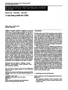
The research process consists of three main stages: an initial stage, an intermediate stage and a final stage, which were devised to address the central research question and achieve the research objectives. These are illustrated in Figure 1.1. In the initial stages, knowledge modelling concepts are identified from four main sources: the knowledge engineering domain, knowledge itself, knowledge modelling techniques, and knowledge engineering methodologies. These concepts were used to develop the early version of the UML profile and were verified using examples from the literature on knowledge-based systems. In the intermediate stage, the initial profile was refined. The refinement process was guided by the general profile requirements, the OMG profile requirements, the OMG request for proposals for KBE services and production rule representation, and the requirements of the hypothetical case studies taken from the literature. The final stage involved further modification of the profile using a UML compliant tool that verified the profile and provided valuable feedback for profile refinement. The profile has also been used in case studies for designing KBS, and the feedback from these modelling activities generated further modification of the profile. Finally, the refined profile was verified and validated using the UML tool, with the final models generated for the case studies used to evaluate the practical aspects of the profile in designing KBS.
21
Knowledge Modelling Techniques
Knowledge Knowledge Engineering Domain
Source of
Source of
Source of
Knowledge Engineering Methodology
Source of
Knowledge-Based System Literature
Knowledge Modelling Concepts
Verify
Initial stage Initial Knowledge Modelling Profile requirements requirements
General Profile Requirement
Hypothetical Case (Literature)
requirements
OMG Profile Requirement OMG RFP Requirement
requirements
Refinement
Intermediate stage Intermediate Knowledge Modelling Profile
verification
used in
UML Compliant Tool feedback
feedback
Case Studies I, II, III
Refinement verification/ validation
verification/ validation
UML Profile for Knowledge Modelling
Final stage
Figure 1.1: Research strategy 1.9
Contributions
The high-level goal of this research is to create an extension to UML for modelling KBSs. Therefore this research contributes towards the field of computer science (and software engineering), particularly in that area of knowledge engineering and artificial intelligence which covers the design of knowledge-based systems.
22
Knowledge-Based System Design
This research has: •
Demonstrated a systematic approach to modelling KBSs using a standardised software engineering modelling language; this has not previously received any attention.
•
Provided transparency between knowledge models and program code. Previous knowledge models are usually hidden within the program code of the knowledgebased system and modelled using a mixture of different techniques. This transparency promotes better understanding between program code and its functionality amongst KBS developers, and enables changes in requirements to be implemented in a straightforward fashion.
•
Enabled better tool support in designing object-oriented knowledge models and, so as to develop KBSs using code generator facilities, it has standard models that can be executed. Most tools only support a particular modelling language; a mixed notation approach generally lacks genuine integration.
•
Made knowledge models much more reusable across applications. The use of a standardised language enables KBSs to be designed in a unified manner and allows reuse of models for the same task type across domains.
Software Engineering
This research has: •
Enabled the knowledge modelling profile to be integrated into the MDA space that is currently in use. Integration with MDA is important for this knowledge modelling language since such languages do not exist in isolation from each other. Through the integration process of MDA, the relation between knowledge models and other language models can be understood, analysed, leveraged and studied.
•
Elicited a better understanding of how the extension mechanisms of UML can be used specifically to create profiles. This is one of the first pieces of work to have extensively studied this in a real case study and shown it to work in practice.
•
Demonstrated that the profile will offer better visibility of knowledge models by defining meta-modelling capabilities. It defines the syntax, semantics, and rules for the knowledge models and enables it to be mapped to the core of UML.
23
•
Provided an insight into how to create UML profiles. There are no specific studies conducted in how to develop a profile from scratch. This will contribute towards creating a short guide to developing this extension mechanism.
1.10
Thesis organisation
1.10.1 Chapter 1: Introduction This first chapter has provided an overview of the thesis. It describes the research background and explains the rationale for conducting the research, the research objectives, the research gaps, the research problems, and the contribution to knowledge. 1.10.2 Chapter 2: Managing Knowledge Chapter 2 is a review of that literature which is related to managing knowledge from both the knowledge management and knowledge engineering perspectives. The chapter starts with defining knowledge management, the need to manage knowledge and the tools used. It introduces different type of knowledge and emphasizes the importance of the knowledge conversion process. Knowledge engineering describes the engineering stages of building tools for knowledge management. This is discussed with an emphasis on knowledge-based systems.
1.10.3 Chapter 3: Knowledge Based-Systems Chapter 3 discusses knowledge-based systems in detail, their background, general architecture and the stages in KBS development. It also addresses the integration of KBS with knowledge management and discusses the benefits of adopting KBS in managing knowledge. The current issues relating to KBS in managing knowledge are highlighted together with the problems faced by the KBS technology in general. 1.10.4 Chapter 4: Conceptual Modelling of Knowledge-Based Systems Chapter 4 describes the importance of conceptual modelling in designing KBS. It reviews that literature which is related to those modelling concepts widely used in KBS conceptual models, the various knowledge representation techniques used in the field of artificial
24
intelligence, and highlights the importance of adopting problem solving methods and ontologies as the means of representing domain knowledge. Current modelling techniques are discussed together with their weaknesses (research problem) and the solution (research objective). The chapter also describes UML and the extension mechanism of UML, highlighting the importance of having a formal extension in terms of the derived benefits to KBS system developers/designers as well as the modelling community. 1.10.5 Chapter 5: Research Methodology This chapter describes the grounded theory on knowledge engineering methodologies adopted when conducting KBS-related research and the acceptance of guidelines for profile development proposed by the standardising agency and researchers. The research strategies are described in detail, together with the techniques for validation and evaluation of the outcomes. 1.10.6 Chapter 6: UML Profile for Knowledge Modelling This chapter presents the complete UML Profile for Knowledge Modelling including the relevant meta-models, syntax, semantics and well-formedness-rules. It details the knowledge modelling concepts, their relations to the profile and the UML meta-model. The development of the profile is the main contribution in this research; it will formally integrate UML and the knowledge engineering discipline and will do so through the conceptual modelling of knowledge when designing a KBS for managing knowledge. 1.10.7 Chapter 7: Profile Evaluation and Validation Chapter 7 discusses the evaluation and validation process of the profile. It will outline the case studies in which the profile has been tested. These are: re-engineered KBSs, and the modelling of new KBS using real-life requirements implemented as a prototype system to evaluate the research. The profile is validated through the use of UML compliant tools to test whether the extension mechanisms are correct and consistent with the UML superstructure as well as adhering to the OMG’s profile requirements.
25
1.10.8 Chapter 8: Conclusions and Future Work This chapter closes the thesis. It discusses the limitation of the research and with it concludes the overall research, and discusses future research directions.
26
Chapter 2 Managing Knowledge This chapter describes the concept of knowledge management for managing organisational knowledge. The needs of organisations to engage in knowledge management initiatives are explained and the technological tools required for this are introduced. The concept of knowledge is described and the types of knowledge that can be managed by technology are highlighted. The chapter ends with a discussion on the discipline of knowledge engineering and its role in developing systems for managing knowledge.
2.1
Knowledge management
Knowledge management (KM) is an evolving trend that spans different domains such as business, organisational studies, management, human resources and computers (Argote et al. 2003). The emergence of a knowledge economy (k-economy), business globalisation and the innovative forces of technology have combined to create a revolution that forces organisations to reinvent themselves (Rowley 1999; Holsapple and Jones 2004) and this is achievable through effective management of organisational knowledge (Garavelli et al. 2004). In recent years, many large organisations have engaged with KM projects either to improve profits, or to be competitively innovative, or simply to survive (Nonaka and Takeuchi 1995; Prusak 1997; Wigg 1997a; Davenport and Prusak 2000; Holsapple and Jones 2004). The process of managing knowledge involves the execution of such actions as knowledge gathering and acquisition, knowledge structuring, knowledge refining and knowledge distribution (Benjamins et al. 1998; Argote et al. 2003; Garavelli et al. 2004; Holsapple and Jones 2004). These processes are implemented using a combination of organisational, social and managerial initiatives as well as appropriate deployment of technology (Marwick 2001; Butler 2003; Carlsson 2003; Garavelli et al. 2004; Moffett et al. 2004). The work reported in this thesis focuses primarily on the technological implementation issues related to KM projects.
27
2.1.1
Definition
Although there is a strong and undoubted interest from the commercial world, the term Knowledge Management still suffers from a high degree of "terminological ambiguity" (Hildreth and Kimble 2002). There is no consensus about what the term really means (Shin et al. 2001; Salisbury 2003; Call 2005) and researchers are constantly attempting to forge their own definitions as shown in the work of Geng et al (2005). Knowledge management involves the systematic management of knowledge resources within the organisation (Zack 1999a; Holsapple and Jones 2004) in order to create value from its knowledge assets (Wigg 1997a; Ergazakis et al. 2005) by creating, coding, storing, distributing and exchanging knowledge using technology as an important contributor and enabler (Davenport and Prusak 1998; Benbya and Belbaly 2005). Nevertheless, it is not completely technology-based as it involves managing people, their tacit knowledge (Currie and Kerrin 2003) and their social interaction (Butler 2003). As there is no agreed definition now, and there is no prospect of one in the near future, the following view of knowledge management, based on that offered by Sallis and Jones (2002) has been adopted in this research. KM is viewed as “a systematic method for managing individual, group and organizational knowledge using the appropriate means and technology. At its root it is to do with managing people, what they know, their social interactions in performing tasks, their decision making, the way information flows and the enterprise’s work culture”. This view represents the scope of the work reported in this thesis. 2.1.2
Need for knowledge management
Knowledge as a resource (Davenport and Prusak 1998) has to be managed from the following perspectives: delivered at the right time; available at the right place; present in the right shape, satisfying the quality requirement and obtained at the lowest possible cost (Wigg 1997a; Wigg 1997b; Carlsson 2003; Holsapple and Jones 2004; Call 2005). The need to manage knowledge differs between organisations as business processes vary between them. However, most organisations need continually to improve business process effectiveness and this is shown in the survey conducted by Ernst & Young Center for
28
Business Innovation and Business Intelligence of 431 U.S. and European companies in 1997 (Binney 2001; Housel and Bell 2001). Almost three quarters of respondents in the survey agreed that knowledge management would be beneficial to them in improving decision making processes (89%), improving responsiveness to customers (84%), improving efficiency of people and operations (73%), improving innovation (73%) and delivering better products and services (73%). A recent survey of senior executives in Western Europe, conducted by the Economist Intelligence Unit (EIU) (EIU 2005), reported similar benefits as to what companies hope to obtain through knowledge management projects. However, improvement in managing knowledge about customers (65%) and business processes and performances (46%) were found to be more important than decision making (44%). Other main benefits reported were: effective product/service development (41%), smoother collaboration across teams and departments (31%), greater customisation of products and services (23%), improved compliance (16%), improved corporate governance (10%), better corporate security (7%) and improved employee loyalty and retention. These clearly indicate that knowledge management needs to infiltrate every aspect of the enterprise to improve business efficiency and productivity. This has resulted in knowledge emerging as the most important commodity; what is bought and sold have knowledge elements in them, and managing knowledge has become the crucial task for organisations (Schreiber et al. 1999; EIU 2005).
Another important need for engaging in KM projects is to overcome the problems of human turnover in organisations. A lifetime’s accumulation of facts, events, procedures and so on is stored in personal memories that enable people to work in, and make sense of, the world that surrounds them. However, with the ending of the single-job-for-life culture, businesses lose much of that knowledge when an individual leaves the organisation. Some have argued (e.g.(Hildreth et al. 1999) ) that this threat of "lost knowledge" is the principal driver behind the emergence of KM and a number of authors have argued that KM provides the answer to the “brain drain” problem (Gardan and Gardan 2003; Lau et al. 2003; Leung et al. 2003). The concept of knowledge, its common classification types, the difference between them and the role of the knowledge conversion process are discussed in the next section.
29
2.2
Knowledge
The nature of knowledge is widely studied in the area of epistemology (Ayer 1964; Gettier 1963) - a branch of philosophy - and in the area of artificial intelligence through knowledge representation (Davis et al. 1993; Mylopoulos 1980). As such there are many definitions of knowledge from these and other various areas such as cognitive science, management, theology and knowledge engineering. However, most of these definitions are very specific to context of the area in which they are used. From the KM perspective, Davenport and Prusak (2000) comment: “Knowledge is a fluid mix of framed experiences, values, contextual information, and expert insight that provides a framework for evaluating and incorporating new experiences and information. It originates and is applied in the minds of knowers.
In organizations, it often becomes embedded not only in documents or
repositories but also in organizational routines, processes, practices, and norms”. Schreiber et al. (1999), taking a knowledge engineering (KE) perspective, define knowledge as: that which “is the whole body of data and information that people bring to bear to practical use in action, in order to carry out tasks and create new information. Knowledge adds two distinct aspects: first a sense of purpose, since knowledge is the ‘intellectual machinery’ used to achieve a goal; second, a generative capability, because one of the major functions of knowledge is to produce new information. It is not accidental, therefore, that knowledge is proclaimed to be a new ‘factor of production’”. Although both definitions provide a different meaning for knowledge, in principle they focus on its importance as a resource that needs to be managed effectively and efficiently. Wigg et al. (1997b) have identified some of the important characteristics of knowledge that make it distinct from other resources used in an organisation. First, knowledge is intangible and difficult to measure. Second, knowledge is volatile, that is, it can ‘disappear’ overnight. Third, knowledge is, most of the time, embodied in agents with wills. Fourth, knowledge is not ‘consumed’ in a process; it sometimes increases through use. Fifth, knowledge has a wide ranging impact within organisations (e.g. knowledge is power). Sixth, knowledge cannot be bought in the market place at any time; it often has long lead times. Seventh, knowledge is ‘non-rival’, it can be used by different processes at the same time. Knowledge is profoundly important in the developed economies and is central to modern industrial organisations.
30
In the literature on KM, there is much debate about what constitutes knowledge, what data is and what information is. George Por at Community Intelligence Labs (CoIL), developed a hierarchy of knowledge based on the relationship between learning and yield (Tuomi 1999) which is shown in Figure 2.1. Yield Compassion WISDOM Choice INTELLIGENCE Predictability KNOWLEDGE Patterns INFORMATION Unfiltered information DATA
Yield = intellectual dividends per effort invested
Learning / Experience
Figure 2.1: The conventional view of a knowledge hierarchy (Tuomi 1999) Data is unfiltered information with no added meaning; it might be sales transactions at a point of sale (POS) terminal. But once it is structured, it becomes information. Sales data that is structured into a sales report becomes information, which is information about the sales. Knowledge is derived when information is interpreted in a particular context and has meaning added to it. When the sales report is interpreted, it becomes knowledge, as decisions can be made with it. If the knowledge is used in making choices between alternative decisions, then it is an act of intelligence. Wisdom is attainable when value and commitment guide intelligent behaviour. Through the process of learning, the value of data, information, knowledge, intelligence and wisdom will increase. Bhatt (2001), however, suggested that data, information and knowledge have a recursive relationship, and their definitions are dependent on the degree of ‘organisation’ and the ‘interpretation’; this is illustrated in Figure 2.2. The ‘organisation’ element is used to
31
differentiate data and information, where information and knowledge are separated by the means of ‘interpretation’.
Knowledge
Data
Information
Figure 2.2: The recursive relationship between data, information and knowledge (Bhatt, 2001) The main reason why the relationship between data, information and knowledge is recursive lies in the basic fact that all of them are interrelated through the IPO (input-process-output) concept in an information system. In the IPO concept, an output of a process can also become an input to another process. Information for one person might just be data to another person, and knowledge for one person might just be information to another. This argument is similar to the one given by Schreiber et al. (1999), who also suggested that the three views (data, information and knowledge) are interrelated and are very much dependent on the ‘context’ of the viewer. There are various types of knowledge in an organisation, namely explicit knowledge, tacit knowledge and cultural knowledge (Choo 2000). There are other classifications of knowledge such as, declarative knowledge, procedural knowledge, heuristic knowledge and group knowledge. Although different authors define knowledge in different ways, a classification of knowledge into two types, tacit and explicit, features in most of the KM literature (e.g. (Nonaka and Takeuchi 1995; Prusak 1997; Zack 1999b). Explicit knowledge can be defined as things that are clearly stated or defined, while tacit knowledge can be defined as things that are not expressed openly, but implied (Choo 2000; Bloodgood and Salisbury 2001; de Carvalho and Ferreira 2001; Herschel et al. 2001).
32
2.2.1
Tacit knowledge
Tacit knowledge is embedded in a person’s memory and is difficult to extract and share with others (Zack 1999b; Choo 2000). The knowledge of how to solve the problem is actually a matter of personal interpretation, ability and skill. While the techniques for problem solving can be learnt in the classroom, the solution created by one employee will differ from that of another. For example, Goguen (Goguen 1997) states: "People may know how to do something without being able to articulate how they do it. In the social sciences, this is called the say-do problem. Some examples are riding bicycles, tying shoe laces, speaking languages, negotiating contracts, reconciling personal differences, evaluating employees and using a word processor." Consequently, tacit knowledge is difficult (or arguably impossible) to code adequately into a set of rules for a knowledge-based system. Nevertheless, some researchers (Nickols 2000; lchmann 2003; Novak and Wurst 2004) believe it is possible to articulate the implicit part of tacit knowledge. Implicit knowledge is incomplete codified knowledge that has not been articulated and the existence of it is implied by, or inferred from, observable behaviour or performance (Nickols 2000; Ichmann 2003; Novak and Wurst 2004). 2.2.2
Explicit knowledge
Explicit knowledge, on the other hand, can be defined as knowledge that can be seen, shared, communicated with others and is easy to manage. It can be communicated because it can be represented/expressed in a formal way using a set of symbols (Choo 2000). For example, a business’s strategic planning report can be circulated within the organisation in any appropriate form and the employees can read and execute the plan. Explicit knowledge can be reports, articles, computer programs, and so on. They can be in electronic or paper form, they can be mathematical formulae or they can exist as diagrams.
However, most explicit knowledge is in the form of documents that contain the work experiences of staff such as raw data, descriptions of cases or events, data interpretation, beliefs, guesses, hunches, ideas, opinions, judgement and proposed action (Jones et al. 2000). Choo (Choo 2000) noted: “explicit knowledge may be object-based or rule-based… knowledge is object-based when it is represented using strings of symbols (words, numbers, formulas), or is embodied in physical entities (equipment, models, substances). Explicit
33
knowledge is rule-based when the knowledge is codified into rules, routines or operating procedures.” This makes explicit knowledge the type of knowledge that can be codified in computer systems, namely knowledge based systems. 2.2.3
Tacit versus explicit
Explicit knowledge can be the property of an organisation even after its inventors or authors leave the organisation (Choo 2000), because it is already captured in the forms mentioned above. However, this is not true in the case of tacit knowledge, which is often lost when the ‘owners’ leave. The only means of having access to this implicit knowledge is when it has been captured by the organisation. One way of capturing the implicit part of tacit knowledge is explained later in the following Section 2.2.4.
Both explicit knowledge and tacit knowledge can be managed using techniques and methods developed in the field of knowledge management and knowledge engineering. However many researchers (Nonaka and Takeuchi 1995; Schreiber et al. 1999; Zack 1999b; Choo 2000) agree that most knowledge is tacit and is more valuable to organisations than explicit knowledge. Despite this, tacit knowledge is the toughest to manage as it resides in peoples’ heads, and is difficult to articulate and share. Based on the research of others, (Bolisani and Scarso 1999) highlight several differences between explicit and tacit knowledge; their findings are summarised in Table 2.1. Explicit knowledge is about knowing something and is regarded as objective knowledge. It is derived from the rationalisation of information and thus can be represented in formulae, diagrams, reports and so on. It can be communicated, codified and transferred using appropriate representation techniques and a shared language (such as knowledge representation languages, formal logic and ontologies). Tacit knowledge, on the other hand, is related to knowing how to do something, which is much more subjective in nature. It is related to ideas, perceptions and experiences. These are difficult to transfer directly by means of a representation because of the lack of common ground (Clark and Brennan 1991) and the fact that tacit knowledge is usually only gained through experience and practice. Another important distinction is that tacit knowledge has a higher degree of ambiguity, as it
34
is open to interpretation, unlike explicit knowledge, which has no room for misinterpretation.
Explicit Knowledge
Tacit Knowledge
Knowing about (objective knowledge)
Knowing how (subjective knowledge)
Rationalisation of facts; formal methods
Systems of ideas, perceptions, experience
Easy to codify, transfer, reuse
Difficult to transfer
Table 2.1: Explicit and tacit knowledge (Bolisani and Scarso 1999)
However, for the purpose of this discussion one of the most important distinctions lies in what Cook and Brown (1999), call "the epistemology of possession". Explicit knowledge is abstract and static: it is about, but not in, the world and accordingly it may be owned without being used. Tacit knowledge, on the other hand, is concrete and dynamic: it is concerned with who we are and what we do; it is not something that can be possessed. Consequently, discussions of “lost knowledge" tend to favour explicit knowledge over tacit knowledge. For the purpose of this research, the focus is on managing codified knowledge that is either explicit or implicit. Understanding the differences between these two types of knowledge is important when identifying the type of knowledge-related application/problems that can be solved/addressed using knowledge engineering techniques as they are applied in knowledgebased systems, which is the focus of this research. 2.2.4
Knowledge conversion
As indicated previously, both explicit knowledge and tacit knowledge must be a part of any KM initiative. Fortunately, both tacit and explicit knowledge can be managed using techniques and methods developed in the fields of KM and KE. However, in the case of tacit knowledge, it must first be "converted" into explicit knowledge (codifying implicit knowledge).
35
Knowledge conversion is the name given to a method of knowledge creation within an organisation and is described as the conceptual relationship between tacit and explicit knowledge (Nonaka and Takeuchi 1995). They view "knowledge conversion" as the repeated application of four processes. (1) Socialisation is the process of transferring the tacit knowledge in one person to tacit knowledge in another person through direct interactions and experience shared between them. (2) Externalisation is the process of making tacit knowledge explicit through articulating one’s tacit knowledge into ideas, metaphors and analogies that can be shared between individuals within a group. (3) Combination is the process of transferring the explicit knowledge through documents, emails, data bases and through meetings. This is achieved by collecting relevant internal and external knowledge, processing it to make it more intelligible, and disseminating it among groups in the organisation. (4) Internalisation is the process of grasping and retaining the learned explicit knowledge into tacit knowledge by an individual. Through internalisation, experiences gained are actualised as concepts, methods and processes performed during experiments and simulation. The knowledge conversion processes are shown in Figure 2.3. Included in this model (shown in italics) are the descriptions by Bolisani and Scarso (1999) for each process of knowledge conversion. The idea of "knowledge conversion", however, remains contentious. For example, Hildreth and Kimble (2002) have criticised the validity of this process, although others such as Schreiber et al. (1999) and Zack (1999b) argue that this framework has provided new insights into the management of tacit knowledge.
To
Tacit Knowledge
Tacit Knowledge
Explicit Knowledge
Externalisation
Socialisation Shares experience, discusses ideas, opinions
Articulate experience in formal models; embed experience into equipment, software, etc.
From
Internalisation Explicit Knowledge
Convert models and formulae into tacit skills; e.g. learn/teach how to use equipment
Combination Re-formulate formal models and data, convert codes, etc.
Figure 2.3: Knowledge conversion model – adapted from Nonaka and Takeuchi (1995) and Bolisani and Scarso (1999)
36
Implicit knowledge is tacit knowledge that has not yet been articulated explicitly and its existence is implied by, or inferred from, observable behaviour or performance. This kind of knowledge is acquired by analysing and understanding the tasks in which the knowledge is used by task analysts or knowledge engineers (Nickols 2000). While there is still some debate as to how widely this knowledge conversion process can be applied, and to what extent certain aspects of tacit knowledge might be "lost" in the process of conversion, Nonaka and Takeuchi's (1995) process has proved to be extremely influential. This is particularly so in knowledge based systems: because only explicit and implicit knowledge can be represented in the knowledge base of a KBS as rules (Choo 2000), the process of knowledge conversion is absolutely fundamental to all activities employed in the development of such systems (Stein et al. 2003). The process of acquiring knowledge for these systems is done through the knowledge acquisition stages of the knowledge engineering process and is discussed further in Section 2.3.1. Knowledge management concerns better management of organisational knowledge using appropriate tools, procedures and techniques from diverse domains. Though managing knowledge is a human-related task, technology can complement human knowledge handling and one such example is the knowledge-based system, which is capable of managing explicit and implicit knowledge. Knowledge-based systems are developed using knowledge engineering techniques that emphasise an engineering approach in the construction of knowledge-intensive systems. They are elaborated in the next section. Having appropriate tools and techniques will ensure that knowledge is fully utilised within the organisation and employees’ knowledge is captured and retained in a form that can be used even when the employee leaves. Section 2.2.5 discusses the tools that are developed for KM. 2.2.5
Tools for knowledge management
There exist several tools developed for KM that perform the task of supporting transactional activities, analytical capabilities, asset management, processes management, human resources development and the knowledge innovation and creation process (Binney 2001; Moffett et al. 2004; Holsapple 2005). The enabling technologies and tools that support these tasks are based on information communication technologies (ICT).
37
Technology plays a catalytic role in supporting KM activities (Moffett et al. 2004; Call 2005; EIU 2005; Holsapple 2005; Tsui 2005), which in some cases are developed specifically within the domain of Artificial Intelligence for managing knowledge. Examples of such systems are knowledge-based systems (KBS), ontologies, business intelligence solutions and organisational memories as well as conventional information system software such as databases and decision support systems (Moffett et al. 2004; Edwards et al. 2005; Ergazakis et al. 2005). Tsui et al. (2000) in their editorial comments made in a special issue on Artificial Intelligence in Knowledge Management support this perspective by arguing that “every Knowledge Management project should embrace some Knowledge Engineering (or Artificial Intelligence or web-based business rule execution) expertise to (attempt to) provide value-added services often needed in knowledge processing.” Devedzic (2001), Moffett et al. (2004) and Ergazakis et al. (2005) have listed the technology tools from Information System (IS) and Artificial Intelligence (AI) that are thought to be the major KM enablers, and these are shown in Figure 2.4.
Intelligent Agents
Ontologies
Databases
Datam ining
Groupware Know ledge M anagem ent
Browsers Decision Support
Docum ent Retrieval
Intranets
KnowledgeBased System s Pointers to People
XML
Figure 2.4: Major technology enablers for knowledge management (Devedzic, 2001) Ontologies, document retrieval, groupware, intranets, KBS, pointers to people, Xtensible Markup Language (XML), decision support, browsers, data mining, databases, intelligent agents are considered to be the major IT/AI components in the KM field. Each of these technologies can either be used by themselves or in combination with other technologies to create hybrid technologies. Examples of these hybrids are ontology based KBS, intelligent agents in decision support and XML for document retrieval. Most current software systems
38
adopt all or some of these technologies and they underpin the services and products of the knowledge economy (Schreiber et al. 1999). This research focuses on adopting technology to manage knowledge using the knowledge-based systems that are highlighted in Figure 2.4 and these systems were developed within the field of knowledge engineering discussed in Section 2.3. Knowledge-based systems are computer systems that are used to assist decision making where human knowledge is represented explicitly as rules in the knowledge base; these are discussed in detail in Chapter 3. However, not all types of knowledge can be managed successfully through the use of technology as some types of knowledge are better managed through human-oriented processes with the support of ICT (Call 2005; Edwards et al. 2005; Holsapple 2005; Tsui 2005). Tsui (2005) believes that successful implementation of any KM project involves the blending of technology, people, process and content. To select the appropriate technology support for KM requires an understanding of the extent to which knowledge can be structured (Hahn and Subramani 2002) and the type of strategy adopted: codification versus personalisation strategy as proposed by (Hansen et al. 1999) and adopted by (Hansen et al. 1999), Carlsson (2003), Garavelli et al. (2004) and Novak and Wurst (2004). The codification strategy relies on knowledge which is stored in databases that are easily accessible by people who need to access the knowledge. The personalisation strategy, on the other hand, focuses on the tacit dimension of knowledge that is embedded in people and is shared through person-to-person contacts. 2.3
Knowledge engineering
Knowledge engineering (KE) was established as a discipline in AI in the eighties with the aim of establishing methods and tools for developing knowledge-based systems in a systematic and controllable manner (Studer et al. 1998; Studer et al. 2000). KE, as with other engineering disciplines, offers scientific methodology together with theories and techniques for analysing and engineering that knowledge (Schreiber et al. 1999). KE techniques are used in building and developing knowledge-based systems (Studer et al. 1998). These are similar to software engineering (SE) techniques (Studer et al. 1998; Motta 1999; Preece et al. 2001; Dieste et al. 2002), but have an emphasis on knowledge rather than data or information processing (Schreiber et al. 1999). The emphasis on knowledge is fundamental as it differentiates KE and SE applications: this is a characteristic of the KE problem domain, which is mainly related to human problem solving with the system
39
architecture based on inference engines (Awad 1996; Preece et al. 2001). KE techniques are similar to SE in that they both advocate an engineering approach (Angele et al. 1998) in developing systems through well-defined development processes that turn system specifications into workable computer programs. Early versions of KBS were built around expert knowledge, as KE activities were approached as a transfer process; however, this approach misses out the problem solving capabilities of the expert. Nevertheless, KBS developers quickly discovered that such capabilities could only be captured through the use of conceptual models in order to understand the problem-solving behaviour of the expert. This leads to defining KE as a modelling process. Sections 2.3.2 and 2.3.3 will discuss this in more detail. 2.3.1
Knowledge engineering process
Both KE and SE development processes have the same objective: to develop the system given the user requirements, in order to solve a particular problem related to the domain (Awad 1996; Acuna and Juristo 1999). Systems development in SE involves the following iterative stages regardless of the methodology adopted: gathering and analysing user requirements, designing the system by translating user requirements into a software specification using conceptual models, coding the software specification into computer programs, testing the program to ensure the agreed results are produced, implementing the system and maintaining the system throughout its intended life span (Jacobson 1992; Pressman and Ince 2000; Sommerville 2001; Priestley 2003). The KE processes for constructing a KBS in general are: requirements analysis involving identifying the scope for the KBS, designing the system by identifying the sources of expert knowledge for the KBS and how to represent them, acquiring the knowledge from the expert through knowledge acquisition techniques and constructing the knowledge base with instances of the domain knowledge, coding the system on target application languages or shells, testing the system to ensure the inference mechanism is working properly and producing the correct results, implementing the system incrementally and performing maintenance on the system (Awad 1996; Schreiber et al. 1999; Preece et al. 2001; Speel et al. 2001; Luger 2004). These iterative stages of KE are compared with SE in Figure 2.5.
40
KBS testing is done in two phases: verification and validation of the system (Awad 1996; Benjamins et al. 1997). In the verification phase, the rules in the knowledge base are analysed for sequence, structure, and specification to ensure the logical correctness of the rules. Then, the validation of the KBS is carried out to test the behaviour of the system in a realistic situation. There are well established techniques for the verification and validation of KBS which are dependent on the implementation domain of the system. For example, in safety-critical applications such as aeroplanes and space missions, the reliability of the KBS is essential, and therefore a formal method verification is essential, whereas in a low-risk application such verification is not necessary (Benjamins et al. 1997). However, testing can also be done on the correctness of the rules during the iterative development process (Friedman-Hill 2003; Awad 1996).
Software Engineering
Knowledge Engineering
Requirement Analysis
Requirement Analysis
System Design
System Design
Knowledge Acquisition
Coding
Coding
Testing
Testing
Implementation
Implementation
Maintenance
Maintenance
Figure 2.5: Comparison of software and knowledge engineering development processes The knowledge acquired from the expert is logically checked for its correctness before populating the knowledge base (Awad 1996). Reliability of the knowledge base is achieved by removing circular rules that are contradictory in meaning or logic, deleting redundant rules that provide different methods for the same problem which causes knowledge
41
duplication, and removing unusable rules that never execute because of the contradictions in the premise of the rule (Awad 1996). In comparison with SE, the KE has one additional stage: that of knowledge acquisition (KA). This stage is vital in KBS development as the KBS is designed around the domain expert’s knowledge of solving problems for a particular task, such as diagnosis, assessment and so on. The acquired knowledge is then used to populate the knowledge base in the form of rules, with which the system will perform reasoning. However, in SE there is no KA stage as the system is intended to capture information rather than reason with it and the actual dataset of the database will be populated by the system user when the system is deployed (Schreiber et al. 1999; Friedman-Hill 2003). Therefore, it may be concluded that the KA stage differentiates the SE and KE domains when developing software systems. 2.3.2
Knowledge engineering as a transfer process
In the early 1980s KE techniques were widely used to construct KBS, which were built on the codifiable knowledge of one or more experts stored in a knowledge base, essentially a process of knowledge transfer (McDermott 1982; Hayes-Roth et al. 1983; Angele et al. 1998; Studer et al. 1998; Schreiber et al. 1999; Studer et al. 2000). This transfer approach is influenced by the success of the Mycin expert system (Shortliffe et al. 1973), which has affected the design of earlier expert systems and expert system shells. Moreover, the development process of KBS was based on the assumption that the codifiable knowledge for the system already existed and just had to be collected and implemented. The knowledge of the expert was directly transferred into the knowledge base by identifying the rules gleaned from the knowledge acquisition process (Studer et al. 1998; Luger 2004). However, this approach fails when the knowledge of the expert is coded with little understanding of how rules are linked or connected with each another (Studer et al. 1998; Schreiber et al. 1999). For example, domain specific knowledge for disease diagnosis is mixed up with strategic knowledge about how the diagnosis should be performed. The transfer approach misses out the experts’ problem-solving experiences and capabilities that are not directly accessible through this approach (Studer et al. 1998; Studer et al. 2000; Luger 2004). The transfer approach also ignores the importance of the tacit knowledge of an expert’s problem solving capabilities (Studer et al. 1998; Schreiber et al. 1999; Luger 2004). This creates a new problem if the knowledge base is to be updated, as changes require substantial effort in reconstituting the coded rules in order to implement the needed changes et al.
42
1998). Consequently, the transfer approach is only feasible for developing prototype systems and fails to scale up when building larger and more reliable KBSs where knowledge bases change (Studer et al. 1998; Schreiber et al. 1999; Luger 2004). These deficiencies have caused the transfer approach to be replaced by the modelling approach (Angele et al. 1998; Luger 2004). During this time, the SE community had already used the modelling approach to construct information systems and it seems that this also suits KBS development (Dieste et al. 2002; Luger 2004). Another direction taken by the KE community during this time to overcome the limitations of the knowledge transfer approach is through Knowledge Sharing initiatives (Neches et al 1991) and the major outcomes of this work are ontologies (Gruber 1993), knowledge interchange format (KIF) (Genesereth 1991), Knowledge Query and Manipulation Language (KQML) (Finin 1994) and Knowledge Representation System Specification (Neches et al 1991). 2.3.3
Knowledge engineering as a modelling process
KE is no longer simply a means of mining the knowledge from the expert’s head and the assumption that knowledge can be directly transferred into computer programs is indeed false (Musen, 1992; Schreiber et al. 1999). The transfer approach was replaced by the modelling approach, which promotes the creation of models that offer similar performance when solving problems in the area of concern (Clancey 1989; Musen 1994; Studer et al., 1998). KE now encompasses “methods and techniques for knowledge acquisition, modelling, representation and use of knowledge”(Schreiber et al. 1999) and KBS development is viewed as a modelling activity (McDermott 1988; Chandrasekaran et al. 1992, Benjamins et al. 1997; Studer et al. 1998) in the analysis and design stages of the systems development (Dieste et al. 2002). The foundation for the modelling process is based on the knowledge-level principle popularised by Alan Newell (Newell 1982), who emphasises the importance of developing problem-solving models of the problem domain rather than focusing on knowledge representation. As a result, two different areas of research have been established based on the knowledge-level modelling principle (Chan 2004). One emphasises the refinement of existing knowledge-level formalisation languages such as KARL (Knowledge Acquisition
43
and Representation Language) (Angele et al. 1996) and KADS (Knowledge Acquisition and Design Support) ML2 language (Flores-Mendez et al. 1998). The other area of research concerns the development of knowledge-level models for a variety of tasks and domains in order to understand the problem-solving techniques used. Knowledge modelling efforts are based on two distinctive approaches, the problem-solving method and domain ontology (Angele et al. 1996; Schreiber et al. 1999; Dieste et al. 2002; Chan 2004). Problem-solving methods (PSM) are domain independent abstract models describing the generic inference patterns for different tasks (Clancey 1985; Angele et al. 1996; GomezPerez and Benjamins 1999). Ontologies define the commonly agreed vocabularies for representing the domain knowledge (Gruber 1993; Gomez-Perez and Benjamins 1999). The focus of the research reported in this thesis is on using PSM techniques for developing knowledge-level models and is discussed in detail in Chapter 4. Figure 2.6 shows the use of conceptual models in KE for developing KBS.
Conceptual Model
Knowledge Acquisition
Programming the KBS If income = 2000 then credit = 3500 If income = 3000 then credit = 5500 If income = 4000 then credit = 7500
Inference Engine
Expertise
Implemented System
Figure 2.6: The role of conceptual models in problem-solving (adopted from (Luger 2004) Studer et al. (1998) feel that building a KBS means building a computer model that has problem-solving capabilities similar to those of a domain expert. It is not necessary to be an exact replica of human cognition; instead it must simulate the thinking processes involved in the narrow area of concern. While experts may consciously articulate part of their knowledge, they will not be aware of a significant part of this knowledge because it is hidden in their skills. This view has been an important part of KE activities and has been supported by many researchers over the years (McDermott 1988; Chandrasekaran et al.
44
1992; Chandrasekaran and Johnson 1993; Schreiber et al. 1999; Juristo and Moreno 2000a; Juristo and Moreno 2000b; Dieste et al. 2002; Luger 2004 and others). Therefore using models KE emphasises how an expert solves a particular problem and develops problem-solving mechanisms in computer systems. It also helps articulate hidden tacit knowledge of the experts’ skills, which is lost in the knowledge acquisition process (as most of the acquired knowledge is explicit knowledge). As such, the modelling process in KBS development mainly involves modelling expert’s reasoning mechanisms (Benjamins et al. 1997; Acuna and Juristo 1999) and the models are useful in bridging the gap between user requirements and the expert, with the KBS performing the required functionality (Angele et al. 1998; Juristo and Moreno 2000b). As a result of the modelling approaches, many KE methodologies have been developed such as CommandKADS, Model-based and Incremental Knowledge Engineering (MIKE), Protégé, and KARL (Benjamins et al. 1997; Gomez-Perez and Benjamins 1999). The usages of conceptual models in developing KBS are discussed in detail in Chapter 4. The shift towards the modelling approach has also enabled KBS models to be re-used in different areas of the same domain (Angele et al. 1998; Studer et al. 1998). In the past, most KBSs had to be designed from scratch every time a new system was needed and they could not interact with other systems in the organisation. 2.3.4
Process role in knowledge engineering
There are several important roles for humans in the process of developing KBS. They are as knowledge experts, knowledge engineers, knowledge-system developers and users (Awad 1996; Schreiber et al. 1999; Luger 2004). Different individuals in larger projects usually perform these roles. However, in smaller projects the same person usually performs a combination of the roles. Knowledge experts are the ‘knowledge’ providers; content is ‘extracted’ from them using different knowledge elicitation techniques such as interviewing, protocol analysis, laddering, concept sorting and repertory grids. Knowledge experts need not be the real expert in the domain but might be a person or a group of people whose expertise is often used in decision-making processes within the organisation. The task of knowledge acquisition from experts, understanding the domain of the targeted system and the analysis
45
of knowledge activities are the role of the knowledge engineer. The engineers will also interact with the knowledge users of the system to gather user requirements for the system and they are the system analysts in a KBS project. The KBS developer will take the knowledge requirement gathered during the analysis stage and present it in the form of analysis models that are used to design and implement the KBS. People use the KBS in order to perform their job function and it is important to include them in the project when gathering user requirements. 2.4
Conclusion
Managing organisational knowledge is crucial because knowledge has become a key factor for business success and survival. As such, it requires effective mechanisms to manage it and KM provides the infrastructure for this. Knowledge management involves two main disciplines, organisational studies and information technology. This has led to different definitions and views of KM. For this research the views suggested by (Sallis and Jones 2002) has been adopted because the application area of KM that is of interest to this research is the knowledge-based system (discussed in Chapter 3). Knowledge can be categorised in many ways, although the two most common are tacit and explicit. Understanding the dimension of tacit and explicit knowledge is important, as there exist different strategies in dealing with them in the knowledge conversion process. Since explicit knowledge can be represented, communicated, codified and expressed, it can be managed effectively by implementing KBS. Furthermore, tacit knowledge that is converted to explicit knowledge can be managed through these knowledge-based systems. Knowledge-based systems are developed using knowledge engineering techniques that are similar to those used in software engineering as both techniques adopt an engineering approach to systems development. Knowledge engineering advocates the modelling approach to constructing KBS and this enables the re-use of the knowledge model in different areas of a domain. It has replaced the conventional knowledge transfer approach, which only concentrated on extracting expert knowledge in the form of rules without making an effort to understand the expert’s reasoning processes in decision-making. The modelling approach adopted in knowledge engineering is similar to the concept of conceptual modelling that is widely used in the software engineering domain. Consequently the modelling techniques, tools and languages used in the software engineering domain can
46
be utilised in constructing models for knowledge engineering. The utilisation of software engineering modelling languages in developing knowledge-based systems is the focus of this research and is discussed in Chapter 4.
47
Chapter 3 Knowledge-Based Systems This chapter presents the technological perspective on managing knowledge using knowledge-based systems. The chapter reviews the KBS architecture literature. It also provides an overview of the current role of this system in managing knowledge and how it is integrated with knowledge management. The benefits of implementing KBS as a tool to manage organisational knowledge are presented. Previous problems relating to introducing the KBS technology are highlighted and how this has been addressed over the years is discussed. The chapter ends with showing the development process of the KBS, highlighting the modelling issues in developing these systems.
3.1
Introduction
The importance of managing different types of knowledge and the technological tools developed in the KE domain for managing that knowledge were discussed in Chapter 2. This chapter discusses one such tool, which is the knowledge-based system. Knowledgebased systems were developed for managing codified knowledge (Awad 1996; Choo 2000; Giarratano and Riley 2004). Widely known as expert systems, these were originally created to emulate the human expert reasoning process (Studer et al. 1998; Giarratano and Riley 2004), hence the name expert system. It became one of the most successful inventions to result from Artificial Intelligence (AI) research (Metaxiotis and Psarras 2003; Giarratano and Riley 2004; Ergazakis et al. 2005) and has been successfully implemented in medical, engineering, business, law, education and other domains (Luger 2004). MYCIN (Shortliffe et al. 1973), used to diagnose infectious diseases, and Digital Equipment Corporation’s XCON for configuring computer systems (O’Connor and Barker 1989) are two of the famous examples of early (successful) expert systems (Awad 1996). This has led to the birth of knowledge engineering,
a domain that supports the development of these systems
(Studer et al. 1998).
48
Expert systems continue to evolve as the need to have a stable technology for managing knowledge grows and their current role as an enabler for KM initiatives has led to greater appreciation of this technology (Studer et al. 2000; Ergazakis et al. 2005; Holsapple 2005). As a result of this evolutionary process, different names have been given to this technology to reflect its current impact and adoption as an established tool for managing knowledge, business rules and process automation in software systems.
3.1.1
Definition
In recent years the terms knowledge-based systems (KBS) (Chandrasekaran and Johnson 1993; Chan 2004), business rule management systems (BRMS) (McClintock 2005), rulebased systems (Friedman-Hill 2003), and knowledge systems (KS) (Schreiber et al. 1999) have been used interchangeably with the term expert system (Awad 1996; Luger 2004). They all refer to the same type of system, where the knowledge (in the form of rules) is inferred in order to arrive at a decision. The Object Management Group (OMG 2004) defines a KBS as follows: “A KnowledgeBased System, or KBS, also known as an expert system, is software that has some knowledge or expertise about a specific, narrow domain, and is implemented such that the Knowledge Base (KB) and the control architecture (i.e. KBE engine) are separate. Knowledge-Based Systems have capabilities that often include inferential processing (as opposed to algorithmic processing), explaining rationale to users and generating non-unique results.” From this definition it can be seen that the important functional features of KBS are that domain specific knowledge is represented in the knowledge base, and this knowledge is used in the reasoning process of the inference engine to generate decisions related to the problem domain. These features are unique to KBS and as such are commonly used to define KBS in the literature (Awad 1996; Giarratano and Riley 2004; Luger 2004).
Nevertheless, there is no single dividing line that differentiates KBS from information systems (IS), as almost all examples contain elements of both knowledge and information within them and are developed using sound engineering techniques (Schreiber et al. 1999). An IS is a set of interrelated components that collects, processes, stores, analyses, and disseminates data and information within an organisation (Stair 1992; O'Brien 1996; Turban et al. 2001). The main differences between IS and KBS are that in a KBS its functionality is embedded in the inference engine (Davis et al. 2004; Giarratano and Riley 2004) and the
49
knowledge about the application domain is represented in an explicit form in the knowledge base (Schreiber et al. 1999; Luger 2004). However, current implementations of certain types of KBS are based on procedural (algorithmic) processing in contrast with conventional inferential processing (Tabet et al. 2005). The KBS’s unique functionality can be seen in the architecture discussed in the next section. 3.1.2
Architecture
Architecture differentiates a knowledge-based system from an information system. The reasoning engine (inference engine) and the knowledge base are the main constituents of a KBS architecture (Awad 1996; Schreiber et al. 1999; Luger 2004). This basic architecture was originally developed and used in expert systems in the late 1970s and is still in use today. The inference engine is usually programmed in a shell-based programming language rather than developed and run with explicit declarative knowledge and information to arrive at a conclusion (Davis et al. 2004; Giarratano and Riley 2004; Luger 2004). The knowledge base contains all the domain knowledge represented as rules (production rules) that are to be consumed by the inference engine during execution (Friedman-Hill 2003; Giarratano and Riley 2004; Luger 2004). The current use of this architecture is a modified version of the original one. The original architecture is shown in Figure 3.1. Here, the reasoning control actually refers to the reasoning or inference engine, and application domain knowledge refers to the knowledge base of the domain.
Reasoning control
Application domain knowledge
Figure 3.1: The basic architecture of the first generation of expert systems (Schreiber et al. 1999) The implementation of this modular architecture is well accepted in the area of KBS development by both researchers (Mills and Gomaa 2000; Chin et al. 2003) and
50
practitioners (Friedman-Hill 2003; Giarratano and Riley 2004); the reasoning engine is the main structural difference between an IS and a KBS. Examples of the current usage of this architecture are shown in Figures 3.2 and 3.3 respectively, adapted from the works of Chau and Albermani (2002) and Rabee (1995).
The knowledge base in both these examples contains the knowledge acquired from the domain expert through the knowledge acquisition process (Håkansson 2001; Giarratano and Riley 2004; Luger 2004) and is represented in the knowledge base as rules, decision criteria, facts and other forms of knowledge representation (Pop and Negru 2002; Luger 2004). As for the inference engine, it contains the necessary reasoning steps that will be used to guide the decision making process (Friedman-Hill 2003; Giarratano and Riley 2004).
User
Context
User Interface
Inference Mechanism
Explanation facility
Expert
Knowledge acquisition facility
Knowledge base
Figure 3.2: Schematic view of a KBS (Chau and Albermani 2002)
According to (Chau and Albermani 2002) and with reference to Figure 3.2, a KBS will comprise three basic components: a knowledge base, the context, and an inference mechanism. The context component, which is additional to the original architecture, contains the current problem scenario that is dynamically constructed by the inference mechanism and the knowledge base. The knowledge is used to manipulate the context, by employing the inference mechanism to make decisions. Other additional components to the basic ones are: the user interface, an explanation facility and knowledge acquisition system. Users will interact through the interface, which will then send the inputs to the system. The reasoning steps and the knowledge used in achieving a particular result will be provided by the reasoning component. The knowledge acquired from the domain experts will populate the knowledge base through the acquisition system.
51
Shown in Figure 3.3 is another example of a KBS architecture that was derived from the earlier architecture given in Figure 3.1. Based on the work of Kulilowski (1989), Rabee (1995) contends that an expert system comprises of the following components: a knowledge base, an inference engine, user interface, knowledge acquisition system and an explanation sub-system. The function of each component here is the same as the components in the architecture presented in Figure 3.2.
Knowledge Acquisition System KB Builder Knowledge Base User Interface ES User
(Objects, Relations, Facts & Domain Specific Reasoning Heuristics)
Inference Engine Domain Independent Reasoning Method
Other Systems (Sensors, Instruments, Display, etc)
Figure 3.3: Architecture of a generic expert system (Rabee 1995)
Judging from the KBS architecture presented in Figures 3.1, 3.2 and 3.3, it may be concluded that the core components of any given KBS are the knowledge base and the inference engine (or reasoning mechanism). However, current architectures differ from the original because new components such as knowledge acquisition, user interface, and the explanation facilities are now added to the core components to make the architecture much more suitable for those current practices used in systems development. One example of this is the user interface component, which has become an important part of any systems development project and takes the form of a conventional graphical user interface (GUI). Due to the growing importance of the user interface element in any system, this component has been explicitly included in the current KBS architecture.
52
3.2
Current issues in knowledge-based system for managing knowledge
In the early 1970s and 1980s, expert systems development was ready for the technology that KM would bring (Gill 1995). Computer scientists from the AI field strongly believed that expert knowledge could be codified, directly transferred and managed through an expert system. However, this proved to be a costly mistake as human knowledge was much more complex and context dependent than was first thought; in the end, not all of it could be coded into a computer program. Nevertheless, work in this area continued, and by the mid 1990s, expert systems were no longer limited to the emulation of expert reasoning, they could also be applied to managing organisational knowledge, such as business rules, procedures and guidelines (Wigg 1997b; Hendriks and Virens 1999; Schreiber et al. 1999). At around the same time, organisations started to recognise the importance of knowledge as a corporate asset and the knowledge management movement started to gain momentum (Wigg 1997b; Studer et al. 1998). However, KM placed more emphasis on managing knowledge as part of a human-related process because it viewed tacit knowledge, which is closely inter-related with human activities, as being the most crucial knowledge for commercial success. By the end of the 1990s, researchers in AI started to realise that organisational knowledge needed to be managed within a far wider context than the traditional KBS application (Binney 2001). Tsui et al. (2000) and Binney (2001) felt that KM provided a macro view of managing knowledge, allowing the formulation of strategies such as knowledge capture, sharing and re-use within an organisation. KE, on the other hand, provided the technical focus in developing KBS. The integration of the AI and KM fields of study has influenced the adoption of techniques such as expert seeking activities and social network analysis used to identify and share knowledge. During this period, KBS technology has been adopted in enterprise and Internet applications through its new role as an embedded system that provides reasoning capabilities. To appreciate the importance of the KBS technology, it is necessary to understand how this technology has evolved over the years and how other external developments in the field of computer science have made the technology much more favourable than its counterparts in the wake of knowledge management programs.
53
The KBS developed in the late 1980s and early 1990s concentrated only on the 'classic' domains of planning, diagnosis, recommendation, tutoring, and prediction (Davis et al. 2004). More recently, and with the growth in the relatively new field of knowledge management (Studer et al. 2000; Lin et al. 2003; Moffett et al. 2004; Holsapple 2005), there has been a greater recognition of the importance of intellectual capital in the knowledge economy and the need to manage it effectively through appropriate technology (Holsapple 2005).
The need to manage knowledge and business rules through technology has caused KBS to be implemented in various (newer) domains and the capabilities of modern KBS technologies have been exploited to manage human competencies, i.e. knowledge. Examples of these domains are: software architecture design assistant (Bachmann et al. 2003), a tool for inferring semantic concepts from visual models (Mills and Gomaa 2000), hospital management (Moreno et al. 2001), clinical management (Torralba-Rodriguez et al. 2003), managing bank loan risk (Yang et al. 2001) and currency exchange advising (Nedovic and Devedzic 2003). Other examples include: legal regulations (Metaxiotis 2004), knowledge-based engineering for managing knowledge related to product design (Gardan and Gardan 2003), learning context management for e-learning applications (Lin et al. 2003), and the production of metals and related compounds (Stein et al. 2003).
Furthermore, while traditionally KBSs were stand-alone applications (Awad 1996; Preece et al. 2001), today they are becoming a part of an enterprise’s information system (Giarratano and Riley 2004; Krovvidy et al. 2005). KBSs have been embedded/integrated with Computer Aided Design (CAD) systems to manage engineering product design knowledge, e.g. Gardan and Gardan (2003) and the MOKA project (Stokes 2001). Other examples of integration can be seen in the field of power system monitoring using the SCADA standard where the knowledge system is successfully used to perform intelligent alarm interpretation (Hossack et al. 2001). Some KBS capabilities have been integrated into Geographical Information Systems (GIS) to provide intelligent advice (Cooper and Jarvis 2004). KBSs have also been incorporated into customer support applications (Krovvidy et al. 2005) for managing mortgages and bank loans. Even e-commerce systems have adopted KBS technology in order to provide recommendations (Chun and Hong 2001; Friedman-Hill 2003; Krovvidy et al. 2005).
54
As a result KBS has matured from a non-scalable technology to a more mature technology for managing knowledge (Studer et al. 1998). While once it was a research laboratory technology, now it is used for demanding commercial applications (Liebowtiz 2001; Preece et al. 2001) and has become a tool widely accepted by industry (Venkatraman and Venkatraman 2000). It provides solutions which cannot be obtained by conventional methods through its unique inferential process (Metaxiotis 2004). There are a number of commercial KBSs in use, for example, Design-a-Trial (DaT) by InferMed Ltd assists in designing and planning clinical trials (Nammuni et al. 2004) and EULE, developed in-house by Swiss Life (a leading provider of life insurance), processes insurance contracts (Reimer et al. 2000) and TURBOLID was developed in Spain for on-line plant-wide supervision of the continuous processes to be found in a sugar-beet factory (Gonzalez et al. 2001). All these solutions are well received and have been judged successful in their respective commercial domains. Because it is a maturing technology and have been widely adopted, there has been a strong demand from industry and KBS developers to standardise both the rule representation language and the development process (OMG 2003a; Krovvidy et al. 2005; McClintock 2005). The motivation behind this is that currently there are interoperability problems with sharing rules between commercial products and between an organisation’s applications (Krovvidy et al. 2005; McClintock 2005). These problems have resulted from company mergers and acquisitions (Selman 2005), industrial legal and trade regulatory requirements and the need to exchange information and knowledge between trading partners. Another area of concern is the growth in the semantic web for enterprise computing, which demands cheaper tools that can write rules faster than writing expensive program codes for syntax tagging (Wagner 2005).
The way forward in addressing these problems lies in having commonly agreed standards for rule representation and the development process of KBS (Abdullah et al. 2002), (McClintock 2005; Selman 2005; Selman and Majoor 2005). Standards will help to drive the acceptance within industry, simplify KBS deployments, and enable exchange of rules between KBSs (Selman 2005). This prompted the Object Management Group, which governs object-oriented software standards, to start the standardisation process for knowledge-based engineering services (OMG 2004) and production rule representation (OMG 2003a; McClintock 2005; Tabet et al. 2005).
55
As discussed earlier in Section 3.1.2, most knowledge systems adopt rules to drive their inference engines. Earlier inference engines (such as CLIPS, VP-Expert, XeprtRule and KnowledgePro) used shell-based production rule systems. These were written in a declarative rather than procedural programming style (Friedman-Hill 2003; Giarratano and Riley 2004) based on algorithms such as RETE (Giarratano and Riley 2004; Kang and Cheng 2004). However, there have been developments in inference engines in which support for embedding features in conventional programming languages such as C++ and Java are implemented (Friedman-Hill 2003; Giarratano and Riley 2004), which simplifies the integration of conventional program code with rule inferencing capabilities (FriedmanHill 2003).
As a result, the Java Expert System Shell (Jess)(Friedman-Hill 2003), based on C Language Integrated Production System (CLIPS), has been developed to enable enterprise software developed using Java to have some built-in reasoning capabilities that can be easily deployed on different hardware (Friedman-Hill 2003; Giarratano and Riley 2004). Use of the Java programming language to develop rule-based applications has prompted the Java Community to develop standards for Java-based rule engines based on the JSR-94 Java Rule Engine API (Selman and Majoor 2005). The JSR-94 specification is popular among vendors and is implemented in ILOG JRules, Jess, Fair Isaac Blaze Advisor, Computer Associates CleverPath Aion, Drools and others (McClintock 2005; Selman and Majoor 2005).
The KBS technology has evolved from the early rule-based reasoning to accommodate other strands of AI research, such as fuzzy logic (Lau et al. 2003; Ammar et al. 2004), genetic algorithms (Lau et al. 2003), case-based reasoning (Lau et al. 2003; Luger 2004), and neural networks (Liebowtiz 2001). This evolution has been beneficial to the knowledge management initiatives community as different KBS technology can be utilised in providing solutions to the problem domains. Nevertheless, production rules are considered as the most convenient approach in representing most business rules and are widely supported by many inference engines (OMG 2003a; Krovvidy et al. 2005; McClintock 2005). Sections 3.3 and 3.4 discuss the benefits and problems of using KBS as a tool for managing knowledge.
56
3.3
Benefits of knowledge-based system in managing knowledge
KBSs offer many advantages as an assistive tool for human in managing knowledge and these can be categorised as: productivity, knowledge preservation, quality improvement, training and job enrichment related benefits (Martin et al. 1996). KBS technology is better appreciated when the benefits of adopting them are well understood. Therefore, the author conducted a comprehensive literature review of the benefits of using KBS technology and has found advantages linked to improved decision quality, improved availability of expert knowledge, improved cost saving, and higher productivity. However, these benefits are only achievable if the quality of knowledge in a knowledge base is thoroughly verified and validated using appropriate techniques, as this ensures the KBS results are accurate and consistent (Awad 1996; Preece 2001; Winn et al. 2005). This is performed by using logical verification and rule verification, which verify the expert knowledge for completeness and consistency. Completeness is the ability of the KBS to produce some decision for all possible inputs, while consistency is the KBS’s ability to produce a standard set of decisions that are true for all possible inputs. Rule verification identifies redundant rules, inconsistent rules, circular rules and unreachable decisions. Validation of the KBS is done by executing the system and comparing the test results against the required performance. This proves that the KBS is producing decisions only for the set of given inputs. Validation and verification is an important area in KE and any KBS that is crucial to safety and health decisions must be verified and validated; this contrasts with those systems that are not safety or mission critical (Preece 2001; Winn et al. 2005). This is other research, which investigates the techniques and tools for implementing these knowledge-intensive systems (Benjamins et al. 1997; Preece 2001; Winn et al. 2005). Using KBS the quality of the decision made increases because there are fewer inconsistencies than if the decisions were performed manually (Horn et al. 2002; Kingston 2004). Results produced by the KBS are consistent (Spronck and Schilstra 2000; Nedovic and Devedzic 2003) throughout its operational lifespan unless it is modified to incorporate new rules or delete older ones. Two copies of the same KBS will provide the same answer to the same problem; human experts do not achieve this level of consistency and such consistency is important in certain domains such as insurance premium calculations for
57
insurance policies (Gill 1995; Bryant 2001). Achieving such consistency is vital as decision quality is an important criterion when adopting KBS, particularly in relation to decisions involving huge amounts of data, variables and information (Horn et al. 2002).
KBSs are also capable of assisting experts in decision making even if the experts’ have that knowledge to hand; this improves the accuracy and timeliness of decisions made (Kingston 2004). Experts are humans, who have the tendency to forget and make mistakes when making decisions. However, when the knowledge of the experts is stored as rules in the knowledge base, such mistakes can be avoided (Horn et al. 2002) provided there are no implementation errors. KBSs will always produce the desired result for every decision case, as they will not leave out any rule (consideration) in the reasoning process. The decision made will always be the same and is reliable (Reimer et al. 2000; Metaxiotis 2004).
Availability of expertise knowledge in an organisation improves as the KBS can be replicated to make the knowledge available at more than one location (Spronck and Schilstra 2000; Nedovic and Devedzic 2003; Kingston 2004). Except in situations such as routine downtime (Stein et al. 2003), KBSs also make expert knowledge available throughout the day for the whole year, delivering the same decisions. This contrasts with human experts, who have fixed working hours or are only available for a limited time throughout a day. They will also experience fatigue, which might have a deleterious effect (Spronck and Schilstra 2000); KBSs are not subject to fatigue and are therefore always available. Implementing KBS in organisations provides the means for reducing operational and other overhead costs (Nedovic and Devedzic 2003; Kingston 2004) through reducing the time needed for decision making, improving the decisions so that they are infallible and consistent (Venkatraman and Venkatraman 2000; Nedovic and Devedzic 2003) and generating reports faster (Spronck and Schilstra 2000). All this reduces the financial costs of making decisions (Venkatraman and Venkatraman 2000). Consequently, KBS decisionmaking strategies can be analysed and studied in greater detail, which in turn can help to improve the organisation decision-making strategies (Kingston 2004) which, in turn, enables better decisions in the future.
58
3.4
Problems with KBS and possible solutions
There is a widely held view that KBSs were unsuccessful as these systems are only initial prototypes and could not be implemented as industrial strength systems, although there are many successful implementations of KBS (Schilstra and Spronck 1998; Friedman-Hill 2003) such as XCON for computer configuration (O’Connor and Barker 1989). However, without proper evaluation, this view had no foundation. It seems that the over-optimistic claims by first generation AI researchers that expert systems is the technology of the future that would replace humans in the decision making process (Awad 1996; Friedman-Hill 2003) was flawed. This is attributed to the failure of not recognising the complexity of tacit knowledge that supports general human reasoning (Friedman-Hill 2003). Today, some of the deficiencies in the technology have been overcome and it is now widely acknowledged (Boury-Brisset and Tourigny 2000) that KBS can assist (rather than replace) humans in solving problems – humans make the final decision, which may involve their tacit knowledge. Liebowtiz (2001), Stein et al. (2003) and Giarratano and Riley (2004) and other researchers have reported that KBSs are playing an important role in several industrial sectors in managing expert knowledge as well as business related rules. Indeed, Kingston (2004) believes that KBSs are an effective method for managing the knowledge in organisations, as long as they are used in the appropriate area and for the appropriate task (Schreiber et al. 1999). The general problems of KBS are discussed in section 3.4.1 and the solutions to these problems are presented in section 3.4.2. 3.4.1
Problems
Gill (1995) has conducted a comprehensive study assessing KBS and his findings shed some light on the problems that inhibited their growth as a tool for managing knowledge. They are widely acknowledged by KBS researchers and developers. The successful adoption of KBS is not primarily dependent on either technical or economic factors. Their lack of success is mainly due to organisational and managerial issues; that is, human related issues, a classic problem in computer science. Among the main areas of concern is the co-ordination of KBS development with that of the organisation’s business and IT strategies (Gill 1995; Friedman-Hill 2003; Luger 2004). The intended system should be able to support the overall strategic information system needs of the organisation and support the business processes. Problems arise when the organisations
59
fail to understand the task that the system would best support (Awad 1996; Schreiber et al. 1999; Giarratano and Riley 2004). Not all tasks can be performed better by the system: there are some that are better performed by humans, especially when the domain task is multidimensional and requires complex judgments (Schreiber et al. 1999; Luger 2004). The automation of the task should also justify the cost associated with its long-term maintenance. Other problem areas include appreciating user concerns (Gill 1995) and expectations, as well as managing the whole development team (Gill 1995; Schreiber et al. 1999). KBSs focus on expert knowledge in a particular application domain. Human experts tend to resist the computerisation of their expertise and if this happens, the whole project could be abandoned. However, this situation is not new as most software development faces this problem especially where the human will be re-assigned afterwards (Gill 1995), and greater co-operation can be gained by assuring the experts and staff that the project is for their own future benefit. Managing the development team members is also an important task as KBS projects are extremely specialised, requiring the team members to have knowledge of both the problem domain and the development tools (Gill 1995; Awad 1996; Schreiber et al. 1999). As a result, the team members are highly skilled individuals, and this poses a great problem to the overall project if they should leave the team early in the development or maintenance periods. Legal implications of KBS decisions are also damaging (Gill 1995), as systems are not accurate in all cases (Awad 1996; Friedman-Hill 2003; Luger 2004) when there are shortcomings in the present set of rules and managers should be aware that such limitations exist, particularly if there is a legal liability associated with the system’s decision. 3.4.2
Solutions
Successful implementation of KBSs lies in understanding the problem domain, assessing the need to have them and selecting the right development tools. This means conducting comprehensive feasibility studies beforehand (Gill 1995; Schreiber et al. 1999; Kingston 2004). Years of experience by Schreiber et al. (1999) and Kingston (2004) have led them to suggest that there are three separate aspects of feasibility studies: the business case feasibility, technical feasibility and project feasibility.
60
During the business case feasibility study, there are important factors that should motivate the development of a KBS: do the organisation’s operations require expertise, is there a problem acquiring that expertise (availability, time restriction) and are there additional benefits such as the production of a learning tool for new recruits? Thus, conducting a business feasibility study would ensure that the system is developed for the right domain for the right problem. The technical feasibility study focuses on the task types that the KBS will have to cover, such as classification, monitoring, design, configuration, recommendation, diagnosis, assessment and control. Other considerations include what form the knowledge should take and how appropriate that form is for symbolic reasoning about concepts, objects or states and whether there be a need for ‘condition-action’ statements such as procedures, regulations or heuristics. It is vital to choose the most appropriate technologies for the task and the appropriate knowledge type. The technical feasibility study would address the need for having the right tool for the right job in developing KBS. The project feasibility study involves measuring the commitment of management to the overall project and determining whether it is willing to make the necessary organisational changes to accommodate the knowledge system. Are users willing to use the system and will they be able to perform the necessary functions with the aid of the intended system? The design team needs to be familiar with all stages of the development process, be comfortable with the chosen programming tool and be able to perform systems maintenance. Additionally, the domain experts must also be willing to co-operate at all stages of the systems development process. The project feasibility study will enable the team to have the right people with the right skill for developing the KBS. Finally, a comprehensive methodology for developing a KBS that incorporates both the aspects of knowledge management and knowledge engineering and addresses the feasibility issues discussed above is required. The CommonKADS methodology (Schreiber et al. 1999) fills this gap. CommonKADS has become the de facto standard for developing KBS; it is used extensively in European research projects. It supports structured KE techniques, provides tools for corporate knowledge management and includes methods to perform detailed analysis of knowledge intensive tasks and processes.
61
The CommonKADS approach views KE activities as a modelling process and as such places greater emphasis on the use of models in developing KBS than the transfer approach. Through a gradual incremental process, a suite of models supports the modelling of the organisation, the tasks that are performed, the agents that are responsible for carrying out the tasks, the knowledge itself, the means by which that knowledge is communicated, and the design of the KBS (Schreiber et al. 1999; Vollebregt et al. 1999). The adoption of the CommonKADS methodology and the use of conceptual models in general for KBS development are presented in the next section. 3.5
Stages in KBS development
The development process of a KBS is similar to any general system development; stages such as requirements gathering, system analysis, system design, system development and implementation are common activities (Awad 1996). The general stages in KBS development can be classified as: business modelling, conceptual modelling, knowledge acquisition, KBS design and KBS implementation (Awad 1996; Parpola 2005), which corresponds to the KE development process discussed earlier in Section 2.3.1 but with slightly different terminology. This is due to the fact that different names are given to the same activities or some activities are grouped together. For example, in the MIKE (Modelbased and Incremental Knowledge Engineering) approach, the development process is classified as knowledge elicitation, knowledge interpretation, knowledge formalisation or operationalisation, KBS design and implementation (Angele et al. 1998). Although the stages in MIKE have different names compared to the general stages, they refer to the same process: developing a KBS based on gathered requirements (Speel et al. 2001; Dieste et al. 2002). The main reason behind this is that different approaches and techniques are used to model the knowledge element and concepts in the system. Figure 3.4 shows the stages of a KBS development and the corresponding stages in the KE development process discussed in Section 2.3.1, along with the description of each stage; these are briefly discussed in Sections 3.5.1 to 3.5.5. 3.5.1
Business modelling
In business modelling, the business processes of an organisation are modelled from a knowledge point of view. The business models are used to view the overall context in which the knowledge model will function (Speel et al. 2001); this is also known as problem
62
domain identification (Awad 1996) or requirements analysis (Preece et al. 2001). This is where the business case, the technical and project feasibility study discussed by Schreiber et al. (1999) and Kingston (2004) are conducted. It allows for an analysis of the actual need for a knowledge-based application and the knowledge that is to be modelled. The components of business modelling are the business model and system context model. A business model will describe the overall view of the business structure, functions, processes, problems and opportunities, the people involved, the knowledge processes and flow, and the knowledge assets of the organisation. The system context model is used to describe the organisational environment with which the system will interact. It typically models the information and control flow between the system and its environment. There are variations in how these stages should interact, but the essence here is conducting the feasibility study and defining the problem scope of the system.
Knowledge Engineering
KBS Development
Requirement Analysis
System Design
Business Modelling
Conceptual Modelling
Knowledge Acquisition
KBS Design
Knowledge Acquisition
Coding
Testing
KBS Implementation (Coding, Testing, Deployment and Maintenance)
Implementation
Maintenance
Figure 3.4: Activities in KBS development with the corresponding stages in KE 3.5.2
Conceptual modelling
Conceptual modelling is an important stage in the KBS development process (Håkansson 2001), as it deals with the creation of implementation-independent knowledge models and defines the expert problem-solving characteristics (Preece et al. 2001; Dieste et al. 2002;
63
Luger 2004). Inputs for conceptual modelling are the knowledge-intensive tasks that are identified during the business modelling and which are considered feasible for KBS development. Conceptual models specify the knowledge and reasoning requirements of the proposed system using either Problem-Solving Methods (PSM) or ontologies (Schreiber et al. 1999; Dieste et al. 2002; Giarratano and Riley 2004). Using the PSM approach 2, the model has three knowledge categories: strategy models (for task level knowledge), reasoning models (for inference level knowledge) and domain knowledge. Each category is used to capture different knowledge structures of the system. Conceptual models are valuable blueprints in designing KBS and the creation of such models is the central focus of this research. Within the field of KBS the process of creating these models is widely referred to as knowledge modelling and is similar to the Platform Independent Model (PIM) concept of MDA. Although conceptual models are vital in KE and are well used in methodologies such as CommonKADS, many of the diagrams are based on a mix of notations adopted from UML, SADT and general flow chart symbols. Consequently, the development of KBS using the modelling approach methodology (i.e. CommonKADS) suffers from modelling notation ambiguity, as some of these notations are non-standard. In the case of UML notations, although it is a standardised language, in most cases it is used together with other notations that make the whole model rather confusing at times as it is neither UML nor SADT. Therefore, standardising on the use of UML for conceptual modelling in designing KBS has become the focus of this research. Chapter 4 will include detailed discussions on the use of a conceptual model for knowledge modelling 3.5.3
Knowledge-based system design
KBS are designed using the problem-solving requirements and the knowledge model from the conceptual modelling stage, together with the knowledge acquired from the knowledge acquisition stage. The steps involved during this design stage are: designing the system architecture, identifying the targeted implementation platform, specifying the architectural components and specifying the applications within the architecture (Kingston 1998; Speel et al. 2001). The outcome of this stage is the design model (Benjamins et al. 1997), which describes the structure of the KBS along with its subsystems, modules, computational
2
The research described in this thesis focuses on adopting PSM for conceptual modelling
64
mechanism and representational constructs (Schreiber et al. 1999) and is similar to the Platform Specific Model (PSModel) concept of MDA. The design model is then implemented on the deployment platform during the implementation stage. 3.5.4
Knowledge acquisition
Knowledge acquisition is the process of knowledge gathering from experts or domain specialists through interactive sessions within the targeted application domain (Schilstra and Spronck 1998; Håkansson 2001; Parpola 2005). It is an essential stage in KBS development as the knowledge gathered during this process is then used to construct the knowledge model and the knowledge base for the proposed system (Schreiber et al. 1999). It involves using a set of techniques and methods to elicit knowledge, such as repertory grids, laddering, card sorting, twenty questions, protocol analysis, structured interviews, and observations (Awad 1996; Schreiber et al. 1999). Knowledge acquired during this stage is usually in the form of rules, heuristics, formulae, lists of terms, diagrams, and so on. Other sources of knowledge used in this process are textbooks, technical manuals, case studies, operating procedures and handbooks (Choo 2000). 3.5.5
Knowledge-based system implementation
During the implementation stage, KBSs are constructed according to the design obtained from the system design model (Benjamins et al. 1997). The system is programmed in the targeted application language (e.g. LISP, Prolog, OO languages, Aion (Schreiber, et al. 1999)). In most cases, it involves the development of a workable exploratory prototype to ensure that the system is functioning as intended and the inference mechanism is working properly and producing correct results or decisions (Awad 1996; Friedman-Hill 2003). If every aspect of the prototype is working well and the expectations of the users and domain experts are fulfilled, the prototype will eventually be expanded into a fully working system (Schreiber et al. 1999; Giarratano and Riley 2004) and deployed into production. Throughout its operational life span, the KBS will undergo a series of periodic maintenance schedules in which new requirements are incorporated, the rule-base is enhanced, operational errors are corrected and performance is improved.
65
3.6
Conclusion
Knowledge-based systems have evolved from being a prototype, laboratory based AI artifact to a mature technology for managing an organisation’s codified knowledge. Because of their current role as a KM tool, these systems are adopted in various domains under different names (i.e. rule-based system, knowledge system, expert systems or knowledgebased system). KBS is unique compared with other systems as it has a distinctive architecture that comprises the reasoning engine together with the knowledge base that constitutes domain knowledge formalised as rules. This is the base architecture of KBS and current implementations extend this to include other components such as the user interface, knowledge acquisition and explanation components. Newly built inference engines are no longer based on shell languages but are implemented in conventional procedural languages such as C and object-oriented languages such as Java and C++. This allows the development of software with embedded reasoning capabilities. KBS are now used in a variety of domains, no longer isolated, but integrated into other application softwares. A number of commercial systems have been successfully deployed, reflecting the success and maturity of this technology. They have improved the quality of decisions, made savings on costs and are practical in even ‘impossible’ situations. Earlier implementation of KBS technology was plagued with problems that still haunt this technology. Much of this relates to the over-optimistic claims of early pioneers, that these systems are capable of replacing human experts. However, such claims have been reduced so that they now assist humans in their decision making processes. Other problems were caused by not having proper feasibility studies and the development processes were not guided by appropriate knowledge engineering methodologies. The development processes of KBS are similar to conventional systems. However, in KBS development, the knowledge acquisition stage differentiates it from other development techniques. Nevertheless, understanding the problem-solving requirements of an expert and representing them as models that can be widely understood remains a problem as different languages are adopted for KBS conceptual modelling. The next chapter will examine the role of the conceptual model used for knowledge modelling in designing KBS.
66
Chapter 4 Conceptual Modelling of Knowledge-Based Systems This chapter details the importance and limitations of conceptual models for developing software systems with a particular emphasis on knowledge-based systems. It explains the role of conceptual modelling as an artifact used when designing software and describes the techniques for representing knowledge. The use of problem solving methods and ontologies in organising domain knowledge is explained. The chapter also provides a review of the important modelling concepts of knowledge-based systems and current knowledge modelling techniques. The justification for standardising the knowledge modelling approach concludes the chapter.
4.1
Conceptual modelling
The work presented so far has described the need to manage knowledge (Chapter 2) and argued how knowledge-based systems can be utilised as a technological tool for KM. This chapter reviews and highlights the importance of using conceptual modelling in building a KBS. “A model is a simplification of reality” (Booch et al. 1999). According to Brown (2004) models are important as they provide abstractions of a physical system, allowing engineers to reason about it by disregarding unwanted details while emphasising the important ones. He further argues that models are essential in the engineering world as they provide the means to understand complicated real world systems. Real systems are entities consisting of interrelated components working together in a complex manner. Models are very much associated with the application domain they represent (Savolainen et al. 1995). That domain will define their practising communities, modelling languages and their associated tools. This is true of all domains, including the field of computer science and artificial intelligence. Models are used to capture the essential features of real systems and enable people to understand the problem space by breaking it down into more manageable parts that are easy to understand and to manipulate (Fowler
67
1999). This is because it is very difficult for the human mind to capture all the features of a system as a mental model and then convey those features to others. Fowler (1999) and Brown (2004) believe that the value of a model in the context of systems development is dependent on the effect it has on the systems being produced. The model is considered as having a value if it increases the quality of the system or decreases the cost in the development process. The model itself has no value of its own. However, in recent years models rather than computer code have become important artifacts in the software development process (Naumenko and Wegmann 2002) and this is the motivation behind the Model Driven Architecture (MDA) approach (OMG 2001a; OMG 2003d)). Conceptual models include specification (design) models and implementation models. Conceptual models (CM) are a description of the problem domain of the software system at a different level of abstraction (Juristo and Moreno 2000b). They are different from computational models (system models) in that conceptual models are mainly used to represent the real world application domain (Mylopoulos et al. 1999) as an analysis model (Juristo and Moreno 2000b). As such, conceptual modelling is a crucial activity in the software development process for both software and knowledge engineering (Dieste et al. 2002). According to (Mylopoulos et al. 1999), a CM consists of a set of primitive terms, which define a collection of basic building blocks for: constructing symbol structures, a mechanism for structuring and managing those symbols; primitive operatives used for building and querying symbol structures, and general integrity rules for defining the set of consistent symbol structure states or changes of states according to certain guidelines. (Hoppenbrouwers et al. 1997) believe that when CMs are qualitatively good, they help provide a comprehensive, accurate and detailed description of the problem domain. The works of (Hoppenbrouwers et al. (1997), Kaindl (1999), Juristo and Moreno (2000b), Selic (2000), Dieste et al. (2002) and Purchase et al. (2004) have highlighted the importance of CM in designing software systems in SE and KE. Accordingly: •
CM provides an overview of concepts and relationships of the real-world elements. It models the dependency, interactions and associations between the real-world elements in a simplified manner and are easy to comprehend.
68
•
CM abstracts the features that are important and hides other details. The abstraction feature of CM is very useful in highlighting aspects of the problem at different levels of complexity.
•
CM facilitates communication between different people in the project team. CM helps unify diverse views of the problem and facilitates in communicating these views across team members efficiently.
•
CM helps eliminate costly errors during the analysis and design stages prior to system construction; mistakes can be identified/analysed earlier in these models.
•
CM provides an orientation on how the system addresses the problems for which it is built by defining the problem context of the system and providing solution specifications to these problems with models that are easy to understood visually.
•
CM provides the specification of the system’s behaviour by describing the flows between activity in the diagram and the necessary action performed during the course.
It is commonly agreed by researchers (Booch et al. 1999; Schreiber et al. 1999; Paige et al. 2000; Naumenko and Wegmann 2002) that conceptual modelling is an important stage in any software system construction. However, the SE and KE communities have developed different modelling techniques that are almost unrelated (Cuena and Molina 2000; Dieste et al. 2002) as a result of fundamental differences in the computational needs of these communities in building software systems (Juristo 1998). Conceptual models in SE are used to represent the problem domain to be addressed by the system (Selic 2003; Dieste et al. 2002). However, in KE the role of CM is to explain in detail the types and structures of the knowledge used in carrying out a task (the knowledge acquisition process) by providing a description of the problem-solving approach (Juristo 1998; Schreiber et al. 1999; Dieste et al. 2002). As a result, although the ultimate goal for both SE and KE is to build software systems, the experiences between them are difficult to interchange (Juristo 1998). Nevertheless, most knowledge engineering modelling notations are adopted from software engineering as this field is much better established. Although CM is useful in designing systems, some of the CM such as UML has several drawbacks, mainly related to its semantics, which are not well-defined and are ambiguous (Alvarez et al. 2001; Steimann and Kuhne 2002) compared to formal methods that have precise semantics. This makes it difficult to define the major concepts of the problem
69
domain, as there can exist inconsistent views of the same domain (France et al. 1998). As a result, CM can be difficult to use and evaluate in a unified manner unless its use is standardised or there are formal semantics attached to the CM for the benefit of system developers, tool vendors and system analysts. Through the standardisation process by bodies such as OMG, a common modelling language has been devised. Such efforts can be seen in the development of the profile for Enterprise Application Integration (EAI), CORBA and Enterprise Distributed Object Computing (EDOC). This in turn helps to realise the benefits of using CM in designing systems and is the motivation of this research. 4.2
Knowledge modelling in knowledge-based systems design
The term Knowledge Modelling usually refers to the knowledge-level principle and the research paradigm in KE for the knowledge acquisition process adopts a modelling approach instead of the previous mining view
(Motta 2002). The ‘knowledge-level’
principle popularised by Newell (1982) for KE purposes requires that knowledge be modelled at a conceptual level independent of any implementation formalism (Dieste et al. 2002). This principle has since influenced much modelling work related to KBS development and is adopted in the major KE works of Schreiber et al. (1999), Cuena and Molina (2000), Motta (2002) and Fensel et al. (2003). Knowledge modelling is similar to the idea of conceptual modelling widely used to refer to implementation-independent problem domain models in SE (Dieste et al. 2002); both terms are used inter-changeably in the KE domain. The ‘knowledge-level’ principle is fundamental to the process of conceptualisation for problem solving (Gómez et al. 2000) and is used in KE for explicit representation of the real world problem to be solved by the proposed system (Juristo and Moreno 2000b). According to Kingston (Kingston 2003), knowledge modelling is the process of representing knowledge, usually in the form of concepts with specified links between them, in text or diagrams; the recording techniques used are similar to those used for information modelling. Milton (2002) argues that knowledge modelling is used in knowledge acquisition activities as a way of structuring projects, acquiring and validating knowledge and storing knowledge for future use.
70
In discussing knowledge modelling, it is necessary to be aware of the types of knowledge that can be represented in the knowledge base of the KBS, as well as the representation technique (Devedzic 1999). The type of knowledge that is the focus of this research is explicit knowledge as discussed in Chapter 2, while the representation technique is based on the object-attribute value and frame discussed in Section 4.3. Knowledge modelling can be performed using various technologies (Motta 2002) or organisation principles (Cuena and Molina 2000) such as the problem solving method (PSM). The domain models are based on task-oriented principles (including PSM) and domain-oriented ontologies. Conceptual models in KE are complex and are classified at three representation levels: strategy models, reasoning models and domain models (Dieste et al. 2002). The CM paradigm is widely adopted in many KE methodologies and projects, for example CommonKADS (Schreiber et al. 1999), Protégé (Grosso et al. 1999), MIKE (Angele et al. 1998), KARL (Fensel et al. 1998), VITAL (Motta 2002), Generic Task (Chandrasekaran et al. 1992) and others. Among these approaches to knowledge engineering, CommonKADS is the most comprehensive and well structured methodology (Decker and Studer 1998; Motta 1999; Motta 2002) and is widely used. Both the CommonKADS and the KARL graphical notations bear a strong resemblance to those used in object-oriented modelling languages (Speel et al. 2001; Dieste et al. 2002). Such notations generally adopt rectangles to represent classes of objects that have attributes, and lines, which represent relationships between classes. In fact it can be argued that most of the graphical notations used in KE are adopted from SE modelling languages (Dieste et al. 2002; Luger 2004). Nevertheless, it is acknowledged that KE has also contributed to SE, since the concept of object oriented programming is based on frame knowledge representation techniques (Luger 2004).
According to Motta (2002), knowledge modelling is not about algorithms or computational improvements in system design. It provides a framework to analyse and engineer knowledge-based problem solving systems that are built on the epistemological distinction in KBS such as task, problem solving methods and domain knowledge.
71
4.3
Knowledge representation
Knowledge representation is one of the fundamental topics in the area of artificial intelligence and KE. It investigates knowledge representation techniques, tools and languages (Brachman et al. 1983; Woods 1983; Davis et al., 1993; Luger 2004). These representation techniques mainly concentrate on representing explicit knowledge in KBS. Knowledge about the domain and the implementation independent reasoning-process of the KBS, however, is usually addressed through the use of ontologies and problem-solving methods, which are discussed in the next section. There are five prominent representation techniques widely used in developing KBS and they are attribute-value pairs (Jackson 1986; Curtis and Cobham 2002), object-attribute-value triplets (Jackson 1986; Partridge and Hussain 1995; Curtis and Cobham 2002), semantic networks (Rich 1983; Jackson 1986; Bench-Capon 1990; Partridge and Hussain 1995; Cawsey 1998), frames (Rich 1983; Jackson 1986; Cawsey 1998; Curtis and Cobham 2002) and logic (Rich 1983; Jackson 1986; Partridge and Hussain 1995; Cawsey 1998). The following Sections, 4.3.1 to 4.3.5, aim to give a brief overview of these techniques. 4.3.1
Attribute-value pairs
Attribute-Value (A-V) pairs are the basic and most common method of representing knowledge in a KBS (Curtis and Cobham, 2002). The A-V pairs method of representation is typically used in representing simple rules in a system using the if-then rule format and is explained further using the sample rules in Figure 4.1. Rule 1
If income > $30,000 then credit type = gold card
Rule 2
If income ≤ $30,000 and credit status = OK then credit type = normal
Rule 3
If income > $10,000 then credit status = OK
Figure 4.1: Examples of rules (adapted from (Curtis and Cobham, 2002))
72
4.3.2
Object-attribute-value pairs
Object-Attribute-Value (O-A-V) triplets are used to represent more than a single object in a KBS. The O-A-V triplets work the same way as the A-V pairs, but they overcome the limitation of A-V pairs, which assumes that all attributes belong to one object. The triplets can be represented by diagrams as they can be considered as a type of semantic network and are used in the knowledge representation of physical objects. This type of representation is widely used as production rules, which is are popular way of representing business rules (Friedman-Hill 2003; OMG 2003a; Giarratano and Riley 2004). An example of this is a person who is the object that has income as the attribute and the amount he received is the value. 4.3.3
Semantic networks
Semantic networks (or semantic nets) were developed for studying linguistics by representing the semantics of English words; this strategy has been adopted for representing knowledge (Giarratano and Riley 2004; Luger 2004). Knowledge is represented as a graph in a semantic network, with nodes in the graph representing concepts and relations between concepts represented using links. Relations between concepts are subclass relations between classes, and instance relations between particular object instances and their parent class. Other relations such as has-part, colour and so on are allowed to represent properties of objects. Figure 4.2 shows an example of the semantic network representation
animal subclass
subclass
reptile
large
size
has-part
mammal
head
subclass colour elephant
grey
instance
instance
likes clyde
nellie
apple
Figure 4.2: A Simple Semantic Network (adapted from Cawsey (1998))
Semantic networks are used to represent knowledge about objects and relations between them in a simple manner. The graphical notations can be used to see how the knowledge is
73
organized. The type of inferences supported by the network is very restricted as it only supports inheritance of properties. It is not suitable to represent very complex knowledge but can be used for certain types of problem.
4.3.4
Frames
Frames are used to represent knowledge because experts represent their knowledge as various concepts (frames) and these are interconnected (Curtis and Cobham, 2002). Frames are considered as a variant of semantic networks and are widely used to represent knowledge in a system (Cawsey, 1998). “Frames are used to capture explicitly organized data structures and the implicit connections of information in a problem domain” (Luger 2004). Object-oriented programming languages have adopted some of the terminology and ideas behind frame systems because of the class and inheritance concepts (Cawsey 1998; Luger 2004). An example of a frame is shown in Figure 4.3. Mammal: subclass: has-part: Elephant: subclass: colour: size:
Animal head Mammal grey large
Figure 4.3: An example of a frame Semantic network representations can be directly translated to frame based representations. Objects in the frame system are nodes in the semantic network, with links becoming slots, and the node on the other end of the link becoming the slot value. Frame systems support the default and multiple inheritance concepts. Subclass objects will inherit all the properties of their parent class. Frame systems also allow for properties (slots) that are just typical of a class, with exceptions allowed, but must be true for all instances. The value of the property that is only typical of a class is called a default value and can be changed by giving a different value for an instance or subclass (Cawsey, 1998). Slots contain information on rules, pointers to other frames, default values and procedures. Both slot values and slots may be frames. Various attributes of a slot can be specified by allowing slots to be frames (Patridge and Hussain 1995).
74
Frame based systems also allow procedures to be included in slots, and these procedures are executed whenever there is a need for the slot value (Cawsey 1998). Frames can be viewed as problem frames (Jackson 2001), a type of design pattern concept introduced to study and analyse problems for systems development activities. 4.3.5
Logic
Logic is another knowledge representation technique that is widely used when developing expert systems (Curtis and Cobham, 2002). “A logic is a formal system which may be described in terms of its syntax (what allowable expressions are), its semantics (what they mean) and its proof theory (how we can draw conclusions given some statements in the logic)” (Cawsey 1998).
The basic type of logic is propositional logic, where a statement as a proposition can be either true or false. Compounded statements are formed by linking together statements using connectives such as AND, OR, or NOT. The value of a compound statement and the semantics of these logical connectives will be given in a truth table as true or false. For example, if X is true and Y is false, then X AND Y is false. On the other hand, X OR Y is true
(Partridge and Hussain 1995; Cawsey 1998). The most important knowledge
representation language is predicate calculus (also known as first-order predicate logic). Predicates are statements or assertions about objects. Sentences in predicate calculus are formed from atomic sentences and express basic facts using a predicate name and some arguments. Arguments in an atomic sentence may be in the following terms: constant symbols, variable symbols and function expressions (Cawsey 1998). One possible way of defining the semantics of predicate logic is in terms of the truthvalues of the sentences. Logic representation is widely used in logic programming languages such as Prolog for developing knowledge intensive applications. However, business applications and users demand simpler knowledge representation that is easier to understand compared to logic (McClintock 2005), which requires a strong mathematical background.
75
4.4
Problem solving methods and ontologies (domain knowledge representation)
Knowledge about the domain is usually addressed through the use of ontologies, while the independent reasoning process is specified with PSM (Studer et al. 2000). Both ontologies and PSM provide components that are reusable across domains and tasks (Gomez-Perez and Benjamins 1999) enabling KBS to be designed, built and deployed quickly (Cuena and Molina 2000).
Ontologies are formal declarative representations of the domain knowledge, that is, they are sets of objects with describable relationships (Gruber 1993). Thus an ontology used for knowledge modelling defines the content-specific knowledge representation elements such as domain-dependent classes, relations, and functions (Kende 2001) for the KBS. (Giarratano and Riley 2004) argue that ontologies are important when building very large KBS in complex domains, which typically consist of thousands of rules. Furthermore, (Chan 2004) believes that the development of an ontology is not easy and requires a detailed analysis of the domain. Nevertheless, Torralba-Rodriguez et al. (2003) have argued that an ontology can also be used for smaller KBS in order to understand the problem domain if the domain is well-defined.
Problem Solving Methods describe the reasoning-process (generic inference patterns) at an abstract level which is independent of the representation formalism (e.g. rules, frames etc) (Gomez-Perez and Benjamins 1999; Grosso et al. 1999; Studer et al. 2000). Problem solving methods have influenced the leading knowledge-engineering frameworks such as Task Structures, Rôle-Limiting Methods, CommonKADS, Protégé, MIKE, Components of Expertise, EXCEPT, GDM, VITAL (Gomez-Perez and Benjamins 1999) and KAMET (Cairo 2004). Most of these frameworks suggest that a PSM decomposes the whole reasoning task into elementary inferences that are easy to understand, defines the types of knowledge that will be used by the inference steps to be completed, and specifies the control mechanisms and flow of knowledge among the inferences. Therefore, PSMs can be considered as design patterns in KE for developing KBS (Schreiber et al. 1999).
76
4.5
Knowledge-based systems modelling concepts/elements
Conceptual modelling is used to abstract the problem domain using elements related to KE technologies discussed earlier in Section 4.2. For KBS modelling, some of these elements are explicitly referred to in the models and a few of them are left out. Also, some of these elements are referred to using different names, yet, in essence, they are the same element. Nevertheless, in this thesis, the author has reviewed the literature related to these elements and has identified nine pivotal elements that are independent of the modelling technique and technology. These elements are: concept, inference, rule, task, task method, static role, dynamic role, knowledge base and fact-base. Most of these elements are similar to those found in CommonKADS since this research adopted them as its methodological foundation. However, the inclusion of these elements is thoroughly verified for consistency in the literature. They are discussed in detail in Sections 4.5.1 to 4.5.7.
4.5.1
Concept
The Concept element is fundamental in representing the category of things in the problem domain that contains, or is related to, a knowledge source. It describes a set of objects and its instances that occur in the domain and which share similar characteristics. Concept characteristics are described using an attribute that can hold a value. This value represents the piece of information belonging to the instances of that concept (Schreiber et al. 1999). Concepts can represent concrete entities such as person, or abstract entities such as transactions. The existence of concepts in a conceptual model is compulsory as it models the domain entities related to the software system and other modelling elements are dependent on their existence. The concept element is commonly referred to by researchers as concept (Cuena and Molina 2000; Mills and Gomaa 2000; Reimer et al. 2000), class (Wu and Cai 2000; Håkansson 2001; Lin et al. 2003; Kang and Cheng 2004), metaobject (Parpola 2005) or domain type (Talens et al. 2000).
4.5.2
Inference
An inference performs the reasoning function in the KBS, based on input from the factbase and matching these with the rules stored in the knowledge base (Schreiber et al. 1999). Inferences are the reasoning processes executed by inference engines (Friedman-Hill 2003),
77
which are central to the system and define the architectural difference between knowledgebased and conventional systems. It is also known as task execution (Cuena and Molina 2000) since it performs either task-based reasoning or rule-based reasoning (Cho 2003). However, when modelling KBS, inferences are generally represented as objects as it is the inference engine that is being referred to in the model. The use and discussion of the inference element can be found in Wei et al. (2001), Allsopp et al. (2002), Gardan and Gardan (2003), Lin et al. (2003) and Davis et al. (2004). Other researchers who have highlighted this element are Håkansson (2001), Chin et al. (2003), Kang and Cheng (2004) and Parpola (2005). 4.5.3
Rule
A rule is a type of instruction that applies to certain situations; any logical statements can be expressed as rules (Friedman-Hill 2003), or business rules (Hicks 2003). A rule is the expression of an attribute value for a concept (Schreiber et al. 1999; Gordon 2000) and is commonly represented in the ‘If-Then’ formalism (Håkansson 2001; Cho et al. 2003; OMG 2003a; Kang and Cheng 2004) or as condition-action statements (Kingston 2004) consisting of the premises of the rule (antecedent) and the action of the rule (consequent) (Qian et al. 2004). Many researchers acknowledge that rules are the natural (Lin et al. 2003; Wu 2004) and simple way (Gordon 2000; Venkatraman and Venkatraman 2000; Chin et al. 2003) of understanding and representing domain knowledge. Nevertheless, Venkatraman and Venkatraman (2000) have pointed out that rules might not be the best knowledge representation technique in all situations. 4.5.4
Task
A task is the reasoning step performed within the problem-solving part of an expert system (Cuena and Molina 2000). A task defines the goal to be achieved by the reasoning process (Cuena and Molina 2000) such as disease diagnosis or assessing credit card applications. Task is also known as control object (Parpola 2005). Tasks are decomposed into smaller tasks (sub-tasks) to achieve the overall goal and each is realised by a corresponding task method in a hierarchical arrangement that shows the general structure of the problemsolving model (Cuena and Molina 2000). Task elements also specify the overall input it receives and output it produces. The use and discussion of the task element can be found in Chung et al. (2003), Gardan and Gardan (2003) and Bass et al. (2004).
78
4.5.5
Task method
A task method describes the realisation of the task through its decomposition into sub-tasks (Schreiber et al. 1999; Cuena and Molina 2000; Talens et al. 2000), and the invocation of operations on dynamic roles, inferences and transfer function (Schreiber et al. 1999). It also specifies the intermediate roles used in storing temporary reasoning results and the control structure of the inference reasoning process (Schreiber et al. 1999). However, the control structure specification is best modeled using an activity diagram as it is a much more suitable representation compared to that of the conceptual model.
4.5.6
Static role
A static role specifies the collection of domain knowledge (rules) that is used by the inference elements in the reasoning process (Schreiber et al. 1999). It provides indirect access to the rules (group of rules) by inference and allows better organisation of larger rule sets according to the functional requirement of the inference or domain knowledge. Some researchers show this specification as knowledge flow from the knowledge base to the inference engine (Mills and Gomaa 2000; Lin, et al. 2003).
4.5.7
Dynamic role
A dynamic role specifies the information flow (input/output) of meaningful facts between the factbase and the inference engine (Schreiber et al. 1999; Lin et al. 2003). It is a run-time component that is not stored in the knowledge base. It identifies a dynamic collection of data (Cuena and Molina 2000) such as the hypotheses for a car fault diagnosis or the results from a credit card application assessment. 4.5.8
Knowledge base
A knowledge base contains all the instances of domain knowledge (in the form of rules) (Schreiber et al. 1999) resulting from the knowledge acquisition process obtained from the domain experts (Awad 1996). The existence of a knowledge base is fundamental to KBS applications and differentiates it from other types of software system (Schreiber et al. 1999; Friedman-Hill 2003). For a non-KBS database, no data sets are written into the database during the analysis stage (Schreiber et al. 1999). However, in knowledge modelling, these
79
data sets are a crucial element in the KBS as they contain the actual knowledge which will be used during the reasoning process (Schreiber et al. 1999; Parpola 2005). Most knowledge base rules are stored in the working memory of the rule engine, though some engines require the storing of rules in an external relational database which allows them to be included in the system based on criteria such as date, time and user access rights (Friedman-Hill 2003; Giarratano and Riley 2004).
4.5.9
Fact base
A fact base is the collection of attribute instances of concepts and all the pieces of information that are stored in working memory (or database), with which the KBS infers (Friedman-Hill 2003; Lin et al. 2003; Giarratano and Riley 2004). The fact base can contain both the premises and conclusions of each rule (Friedman-Hill 2003). During the reasoning process, the inference engine will decide which rule to fire, triggered by one or more of these attribute instances. In smaller applications or rule engines the fact base is defined as the content of the working memory directly, which works like a relation database. However, the usage of working memory in larger applications is time consuming and difficult as it involves vast amounts of data contained in many databases. Such databases are usually connected directly to the inference engine, which extracts the needed information. Although this element is crucial for a KBS, the existence of a fact base in KBS conceptual models is extremely rare and can only be found in the works of (Mills and Gomaa 2000) and (Lin et al. 2003).
4.6
Review of current knowledge modelling techniques
The importance of knowledge modelling in developing KBS has been discussed by Schreiber et al. (1999), Richards (2000) and Studer et al. (2000). All argue that models are important for understanding the working mechanisms within a KBS, such as: the tasks, methods, how knowledge is inferred, the domain knowledge and its schemas. Using conceptual modelling, systems development can be faster and more efficient through the reuse of existing models for different areas of the same domain. Amongst the many techniques used to model knowledge, the most common are CommonKADS (Schreiber et al. 1999), Protégé 2000 (Grosso et al. 1999), the Unified Modeling Language (UML) (OMG 2001b; OMG 2003b) and Multi-perspective Modelling (Nuseibeh 1996; Chen-Burger 2001).
80
These modelling techniques are reviewed here in term of how they are used for knowledge modelling during the development of a KBS, how they complement each other and what their limitations are. This review helps identify the most appropriate modelling technique and language that can be extended to provide a standard for knowledge modelling 4.6.1
CommonKADS
CommonKADS has become the de facto standard for knowledge modelling and is used extensively in European research projects (Bravo-Aranda et al. 1999) and KBS development in general. It supports structured knowledge engineering techniques, provides tools for corporate knowledge management and includes methods that perform a detailed analysis of knowledge intensive tasks and processes. The CommonKADS knowledge modelling technique has influenced many other techniques and methodologies for KE such as KAMET II (Cairo 2004), KARL (Fensel et al. 1998), and MIKE (Gomez-Perez and Benjamins 1999).
A suite of models is at the core of the CommonKADS methodology (Schreiber et al. 1999; Allsopp et al. 2002) with the knowledge model being central (Schreiber et al. 1999) and this is the focus of this discussion. The suite supports the modelling of the organisation, the tasks that are performed, the agents that are responsible for carrying out the tasks, the knowledge itself, the means by which that knowledge is communicated, and the design of the KBS. Table 4.1 adapted from (Schreiber et al. 1999) provides an overview of the main constructs of the knowledge model. CommonKADS developers claim to have incorporated an object-oriented modelling paradigm and use UML notations such as class diagrams, use-case diagrams, activity diagrams and state diagrams (Schreiber et al. 1999). However, its object-oriented models here are somewhat confusing as they are integrated with other modelling language notations such as SADT to represent data flow and data stores, which are typical of data flow diagrams (DFD). CommonKADS also has its own graphical notations based on PSM models for task decomposition, inference structures and domain schema generation; the relation between these and UML notations is not precisely defined.
81
Category
Construct
Task
task
Description a problem statement of what needs to be achieved; also specifies input and output
knowledge task method
a way to achieve a task by decomposing it into subtasks, inference and transfer functions; also defines a control regimen over the decomposition
Inference
inference
a primitive reasoning function that uses a part of the domain knowledge to achieve a basic problem-solving
knowledge
step dynamic role
input or output of an inference; signifies a placeholder and an abstract name for domain objects “playing” the role
static role
the static knowledge used by an inference, also defined as a placeholder for domain objects (e.g., rule set)
Domain
transfer
a primitive function needed for interacting with the
function
outside world
domain schema
a set of domain-type definitions; a domain schema can be imported into other schemata
knowledge concept
a group of “things” with shared features; cf. “object class” or “entity”
relation
a set of tuples that relate “things” to each other; cf. “associations”, ER-type relationships
rule type
expressions about concepts/relations in an antecedent /consequent form
knowledge base a set of domain-type instances (usually rule instances) that can be used as static knowledge by one or more inferences Table 4.1: Constructs in the CommonKADS knowledge model (Schreiber et al. 1999) CommonKADS notations are used to represent the PSM structure of the KBS, while the UML class diagram is used to represent the static information structure of the application domain. Activity diagrams are utilised for modelling the control structure of a task method and the organisation’s business processes, and state diagrams are used to describe the
82
dynamic behaviour of the KBS. The CommonKADS methodology and models are described in detail in Chapter 5. CommonKADS is a well-received methodology that is widely adopted in KE for building KBS. However, using mixed notations creates problems; there is limited or no tool support available; it is difficult to train modellers on different notations; it can easily lead to inconsistent designs; and it may be difficult to integrate KBS designs into other software designs. Nevertheless, the problems of mixed notations used in current KE modelling approaches can be addressed by adopting a standardise modelling language as proposed by the author (Abdullah et al. 2002; Abdullah et al. 2004) provided it is based on a sound methodology such as CommonKADS. Indeed, the adoption of CommonKADS is vital in the standardisation efforts and this is clearly reflected in the OMG work on production rule representation and knowledge-based engineering (OMG 2003a; OMG 2004). 4.6.2
Protégé - 2000
Protégé was developed for modelling domain specific applications using an ontology (Grosso et al. 1999) at Stanford Medical Informatics. Protégé 2000 is defined as “an extensible, platform-independent environment for creating and editing ontologies and knowledge bases” (Protege 2002). The Protégé 2000 knowledge modelling environment is a frame-based ontology editing tool with knowledge acquisition tools that are widely used for domain modelling (Noy et al. 2001; Giarratano and Riley 2004). It is a platform which can be extended to support graphical and media components such as graphs, tables, sounds, images and videos. It is extensible through its API and its component-based architecture supports the creation and editing of Resource Description Framework (RDF) schemas, Xtensible Markup Language (XML) schemas and the Web Ontology Language (OWL). Frames are the main building blocks for a knowledge base (Noy et al. 2001). The Protégé ontology (which models the domain) has classes, slots, facets and axioms. Classes are abstract representations of domain concepts. “Classes in Protégé 2000 constitute a taxonomic hierarchy and are templates for individual instance frames” (Noy et al. 2001). Slots are properties or attributes of classes. Slots are first class objects in Protégé 2000; they can be used globally or locally. Facets are properties or attributes of a slot and are used to specify constraints on slot values. The constraints include slot cardinality, (i.e. it specifies
83
the number of values the slot can have), value type for the slot (such as integer, string) and minimum and maximum values for a numeric slot. Axioms define additional constraints on frames; these may link values together, or exploit Knowledge Interchange Format (KIF)based predicate logic.
Figure 4.4: Sample screenshot of the Protégé editor. Protégé’s instance information is acquired using on-line forms and that are composed of a set of graphical entry fields which provide an easy-to-use user-interface - an important feature of Protégé 2000. It automatically provides a form to acquire instances of a class when the user defines a class and attaches a template slot to it. The user can customise the form by changing the layout, or changing the form’s field labels and can choose different ways of displaying and acquiring slot values (Noy et al. 2001). The knowledge acquisition process in Protégé 2000 consists of three steps. First, a class and its template slot have to be defined. Second, the form to acquire the instances of the class has to be laid out. Finally, the class instances are acquired. Each class has an associated form and is used to get the instances of the class (Noy et al. 2001). A knowledge base in Protégé is developed in the
84
following sequence: (1) concepts and their relationships are defined by an ontology; (2) the domain experts enter their knowledge of the domain area using the domain-specific knowledge acquisition tool; (3) problem-solving techniques are used to answer questions and problems of the domain using the knowledge base. An example of a Protégé editor window is given in Figure 4.4. This example shows the instances tab of a Protégé editor, used to acquire instances of the classes defined in ontology. A review on Protégé shows that it provides a tool for editing ontologies, which is an emerging trend in systems development (Jurisica et al. 2004) and it supports a variety of ontology standards. However, the use of ontology is still elusive, as it requires designers to have prior knowledge of creating ontologies before adopting them in KBS development; not many system designers are familiar with this process. The field of ontology design also needs standardisation, as there are many different ways in which an ontology can be represented such as OWL, DAML + OIL (DARPA Agent Markup Language + Ontology Inference Layer), and ONTOLINGUA. Thus, there have been several proposal by researchers such as (Cranfield and Purvis 1999; Baclawski et al. 2001; Chan 2004; Djuric et al. 2004).
4.6.3
Multi-perspective modelling
Multi-perspective modelling (MPM) enables a number of techniques to be used together, each technique being the most appropriate for modelling that particular aspect of knowledge. Chen-Burger (2001) believes that this multi-perspective modelling technique is important because organisational knowledge is very complex and heterogeneous, and there is no single method that can model all of these accurately and appropriately. The MPM technique is used to produce different models of the same artifact and it supports different viewpoints (Kingston and Macintosh 2000). The MPM approach is similar to modelling techniques such as UML and Structured System Analysis and Design Methodology (SSADM) as these techniques also advocates the use of multi-modal in the analysis and design stages of systems development. Nevertheless, MPM has tool support issues as the generally available tools only support a particular technique.
It has its roots in SE, where it is used to gather requirements for software development projects using multiple viewpoints (Nuseibeh and Finkelstein 1992; Nuseibeh 1994; Nuseibeh 1996) because it is impossible to capture all aspects of a system using a single
85
model/view. For example, in a systems development project, the manager has an overall view of the project; the system analyst’s view is that of the requirements for the proposed system; the system designer’s view concentrates on aspects of the design; and the programmer’s view is concerned with the construction of programming code for each module. Different people are involved at different stages of the project and have different perspectives on the project. Therefore, these perspectives of the project require different levels of abstraction (Kingston and Macintosh 2000).
The appropriate modelling technique is selected from business management techniques (such as soft system modelling and PERT charts), software engineering techniques (such as flow charts, entity-relationship diagrams and object-oriented analysis and design) and knowledge engineering techniques (such as CommonKADS and VITAL) (Kingston and Macintosh 2000).
The disadvantage of MPM (and this is also true for CommonKADS) is that the knowledge modeller needs to know a number of modelling techniques. Furthermore, integrating different models to represent a system is a cumbersome process as different techniques have their own distinct features that are not supported by the other techniques and tools. Adopting these approaches means that the modellers have to be trained in techniques with which they are not familiar, in order to perform the knowledge modelling task. This is expensive and time consuming.
4.6.4
Unified Modeling Language
The Unified Modeling Language (UML) together with the Object Constraint Language (OCL) is the de facto standard for object modelling in software engineering (France et al. 2004) as defined by the Object Management Group (OMG). OMG’s MDA efforts in providing an open, vendor-independent approach to system interoperability are being realised with UML as the modelling standard (Brown 2004).
UML is a unification of three previous important software development approaches: Jacobson’s Object-Oriented Software Engineering (OOSE), Rumbaugh’s Object Modeling Technique (OMT) and Booch’s method (Paige et al. 2000; Chen-Burger 2001; Scott 2001). UML provides notations to specify, analyse, visualise, construct, and document both
86
physical and abstract aspects of software systems using object-oriented concepts (Chan 2004).
There are three components in UML: things, relationships and diagrams. Things are the core entities of a model that are linked by relationships and grouped as a meaningful set using diagrams (OMG 2001b; OMG 2003b). There are four types of things in the UML: structural things, behavioural things, grouping things, and annotational things. Structural things are the nouns of the UML model and are either conceptual or physical; there are seven types: class, interface, collaboration, use-case, active class, component, and node. “Class” describes objects that share similar attribute relationships, semantics and operations. Interface refers to a group of operations, which define a service provided by a class or component. Collaboration specifies an interaction and is a group of roles and other elements that collaborate together. Use case is a description of a sequence of actions performed by the system that provides results to the action performer. An active class is a class whose objects own one or more processes or threads and therefore can initiate control activity. Component refers to a physical and replaceable part of a system that conforms to and provides the realization of a set of interfaces. Node is a physical element that exists during execution and represents a computational resource. Behavioural things are dynamic parts and are the verbs of UML models. They are: interaction, which refers to the communication between a group of objects, and state machine, which is a behaviour that specifies the sequences of states an object goes through during its lifetime in response to events. Package is the basic grouping technique used to organise UML models, and annotations are notes used to explain parts of the UML model. Relationships are used to describe the connection between instances of model elements such as class. The four kinds of relationships in UML are: the dependency relationship, which is used to show the dependency between things (independent and dependent), association, which refers to the structural relationship that links objects, generalisation, which is a specialised relationship, where such an element’s object can substitute for a general element’s object, and realisation, which is a semantic relationship between classifiers.
Diagrams are graphical representations of groups of elements used to depict different aspects of a system. There are nine UML diagrams and these are: class diagrams, object
87
diagrams, use-case diagrams, sequence diagrams, collaboration diagrams, state-chart diagrams, activity diagrams, component diagrams and deployment diagrams. UML has rules that are applied to models so that they are well-formed semantically. UML has semantic rules for the following: names, scope, visibility, integrity and execution. Common mechanisms are used to ensure the models conform to patterns with common features. The mechanisms are as follows: specifications, adornments, common divisions and extensibility mechanisms. The OCL is a non-executable text based language for specifying constraints and queries, and is used for writing navigation expressions, Boolean expressions and queries in UML (Warmer and Kleppe 2003). It is also used to construct expressions for constraints, guard conditions, actions, pre-conditions, post-conditions, assertions and other UML expressions. However, OCL is not yet able to provide support for direct invocation of methods that change the system state, a requirement of the action clause of the production rule (OMG 2003). There are attempts to use action semantics to perform this invocation (Tabet et al. 2005), and work in this area still continues. Although UML is very popular and widely used as the modelling language for business applications, its use for knowledge modelling is limited. This is due to the fact that the usage of UML in modelling KBS has not been standardised (OMG 2003a), as there is no commonly agreed consensus on what KBS and KE concepts should be represented in a KBS design, and how rules should be defined and modelled. Nevertheless, there have been several attempts to use UML for knowledge modelling but such comprehensive efforts are only reflected in CommonKADS (Schreiber et al. 1999) and Methodology for Knowledge Based Engineering Applications (MOKA) (Stokes 2001).
The CommonKADS modelling approach is not entirely based on UML notations and adopts a more liberal MPM technique with UML being one of the modelling languages. MOKA models only specialise in the representation of engineering design knowledge, which is very complicated and specific to the engineering domain. Furthermore, both CommonKADS and MOKA only utilise part of the UML specification on an ‘as needed basis’ and make informal modifications to the structure of the diagrams. This need not be the case as one of UML’s important features is that it is an extensible language (Marcos et al. 2001) and can be formally specialised by introducing UML Profiles (Lujan-Mora et al. 2002; Rubart and Dawabi 2002) as proposed by the author (Abdullah et al. 2002).
88
4.7
Standardising knowledge modelling language
A UML profile specialises the UML for a specific domain, in this case the KE domain. There have been several attempts to standardise the knowledge modelling language by developing UML profiles for the KE domain, but such efforts have only been limited to the configuration design task (Felfernig et al. 2000a; Felfernig et al. 2000b; Felfernig et al. 2002c) and the MOKA Modeling Language (MML) which is aimed at knowledge-based engineering applications (Stokes 2001). Nevertheless, these efforts have failed to scale up as the profiles developed are not truly a UML profile; they did not adhere to the OMG’s profile extension requirements (OMG 1999; OMG 2003b) and are not generic profiles that can be used for other task types such as diagnosis, assessment, classification and planning.
However, because of the demand from industry and from commercial inference engine tool vendors (Krovvidy et al. 2005; McClintock 2005; Selman 2005; Selman and Majoor 2005) the OMG (OMG 2003a; OMG 2004) has started looking into standardising the use of UML for knowledge and rule modelling in the context of KBS and knowledge-based engineering. This is an on-going challenge (Tabet et al. 2005) which will eventually enable the sharing of rules and KBS information between inference engines and applications. The benefits of using UML compared with other modelling languages are that it is a standard, which is easy-to-use and learn (Marcos et al. 2001; Koch and Kraus 2002) with many publications available on it (Naumenko and Wegmann 2002). Furthermore, it has better tool support from a variety of modelling tool vendors (Fuentes et al. 2002; LujanMora et al. 2002), and it has a larger user group (Koch and Kraus 2002) consisting of both software and knowledge engineers. Finally, it is a standardised language that is governed by OMG and continues to evolve through strong support from industry and academics (Cook 2000; Brown 2004).
The UML can be enhanced for knowledge modelling by developing an extension to the language through either the profile or meta-model extension mechanisms as proposed by OMG (2003b). In developing the profile, the characteristics of the UML and how the language itself was designed and defined must be understood. The next section will briefly explain the UML architecture, and the role of the Meta Object Facility (MOF) in defining UML.
89
4.7.1
Characteristics of Unified Modeling Language
The UML is defined using the general four-layer meta-modelling architecture (Cook 2000; Medvidovic et al. 2002; Clark et al. 2005) shown in Figure 4.5, which is based on the original OMG MOF 1.X standard (Clark et al. 2005). OMG’s Meta Object Facility (MOF) provides the standard modelling and interchange constructs and is the foundation specification for modelling languages that are used in MDA (OMG 2001a; OMG 2003d). MOF constructs are used to define standard OMG models, including UML and Common Warehouse Meta-model (CWM). This common foundation offers the basis for model/metamodel interchange and interoperability that can be transmitted via XML Metadata Interchange (XMI) and manipulated by MOF-compliant tools and code generators. Consequently, all models developed by OMG are defined using MOF meta-models as their core meta-meta model layer constructs.
M3 Layer meta-metamodel Class
MOF
M2 Layer metamodel UML Metamodel
UML Profile
Custom Metamodel
Class
Operation
Attribute
M1 Layer model Account UML models
Models based on custom metamodel
balance: Float deposit ( )
M0 Layer instances anAccount Instances (Java, C++, XML, Database)
Figure 4.5: MDA four-layer MOF-based metadata architecture with example The meta-meta-model layer (M3) defines a language for describing the properties of the meta-model layer and is based on the MOF standard (OMG 2002). The meta-model layer (M2) contains the legal specification of a given modelling language; for example, the UML meta-model defines UML elements such as Class, Attribute, and Operation. The model
90
layer (M1) models the domain-specific information of the software system such as the classes of an object-oriented system using UML class diagrams. Finally, the instances layer (M0) is used to construct specific instances of a given model and contains the data of the software system such as the instances populating an object-oriented system at run time.
All UML modelling takes place within the four-layer MOF-based model architecture (Atkinson and Kuhne 2002) and any additional construct or specialisation of existing constructs of standard UML can only be achieved by extending the language in a controllable way using the extension mechanism of UML (D'Souza et al. 1999; Engles et al. 2000; Perez-Martinez 2003) as proposed by OMG (OMG 1999; OMG 2003b). The extension mechanism will provide intuitive and expressive modelling features for a certain domain (Engles et al. 2000) based on the specific modelling requirements of that domain (Schleicher and Westfechtel 2001). Details of how UML could be extended are discussed in the following section. 4.7.2
Extension mechanism of UML
The UML extension mechanism was first proposed by OMG (OMG 1999), in which a mechanism termed “Profile” to the UML 1.3 specification is defined (D'Souza et al. 1999). The profile enables metaclasses from existing meta-models to be extended so as to adapt them for different needs including the ability to make the UML meta-model available for different platforms (such as J2EE or .NET) or domains (such as real-time or web modelling) (OMG 2003b). The profiles mechanism is coherent with the OMG Meta Object Facility (MOF) (OMG 2003b). There exist two mechanisms for extending the UML as defined by OMG: Profiles and Meta-model Extensions (Cook 2000; OMG 2003b; Perez-Martinez 2003), both of which are known (confusingly) as profiles (Muller et al. 2003). The UML Profile for Enterprise Application Integration (EAI), UML Profiles for CORBA, UML Profile for Enterprise Distributed Object Computing (EDOC), UML Testing Profile, and UML Profile for Schedulability, Performance and Time are some of the formal profiles developed by OMG.
91
4.7.2.1 Profile extension The profile mechanism is not a first-class extension mechanism as it does not permit the modification of existing meta-models (OMG 2003b). Therefore the semantics and the structure of UML meta-models cannot be changed, and the introduction of new elements to the meta-model are not permitted (Perez-Martinez 2003). So, the purpose of profile is to provide a direct mechanism for adapting an existing meta-model using constructs that are related to a particular domain, platform, or method (D'Souza et al. 1999; Cook 2000; OMG 2003) and grouped in a profile. Additional constraints that are specific to the profile can be added, but changes to existing constraints in the UML meta-model are not allowed (OMG 2003b).
Profiles are commonly referred to as the “lightweight” built-in extension mechanism of UML as they provide a lightweight approach to extending UML to provide new modelling constructs (Cook 2000; Perez-Martinez 2003). They are easily supported by UML MOF compliant tools as no “meta case” tool functionality is required to support the profile (Cook 2000) and the profile does not affect the interchange formats (Koch and Kraus 2002). Profiles contain a predefined set of Stereotypes, TaggedValues, and Constraints that collectively specialise the UML. Details of profiles and how they are developed are discussed in Chapter 5. 4.7.2.2 Meta-model extension Meta-model extensions are first-class extensions of UML that are dealt with using MOF. These provide a completely new meta-model that is defined - there are no restrictions imposed on introducing meta-classes and relationships (OMG 2003b). This is commonly known as the “heavyweight” extension mechanism to UML and is considered to be a more flexible approach since new concepts may be represented at the meta-model level. This approach is more attractive when the semantic difference between existing UML modelling elements and the newly defined modelling elements starts to grow (Muller et al. 2003).
However, the differences between the meta-model extensibility and profiles start to become less significant when methodological restrictions (for example a new meta-model cannot be modified, it can only be extended) are imposed (OMG 2003b). Furthermore, these types of extension are not readily supported by UML tools and, as a consequence, tools to implement
92
the meta-model extension have to be developed from scratch. A formal example of a metamodel extension is the UML Profile for Testing (OMG 2003c).
4.7.3
UML Profile extension for knowledge-based systems design
Extending UML to address domain specific modelling requirements will become increasingly important as a result of MDA being applied to a wide range of different domains (Muller et al. 2003; Brown 2004), including knowledge-based applications. Standard extensions would allow KBS developers to share common graphical notations and vocabulary, and allow standard documentation of the systems to be shared easily (Fuentes et al. 2002; Brown 2004). The author has adopted the profile mechanism for extending UML as the existing constructs of UML are adequate for representing the modelling concepts of KBS without having to create new metaclasses. Another important consideration is that KBS designers have the much needed tool support for designing knowledge models if the extensions are based on profiles; these are easier to deploy in UML compliant tools (OMG 1999; Cook 2000; Muller et al. 2003).
Furthermore, profiles have been widely adopted by researchers in various domains such as web engineering (Fuentes et al. 2002; Koch and Kraus 2002), Model-Based Risk Assessment (Houmb et al. 2002), relational database design (Marcos et al. 2001), Profile for CORBA components (OMG 2005) and software product lines (Ziadi et al. 2004). The metamodel extension has not been so popular. Newly developed KBS are built by software houses, which in most cases adopt the UML as the in-house modelling language. Therefore, system developers with a background in UML are usually able to comprehend a KBS model that is based on a UML profile (Koch and Kraus 2002); it is the natural choice of modelling language among developers these days (Jurjens 2002; Naumenko and Wegmann 2002).
93
4.8
Conclusion
Conceptual modelling is an important artifact in software systems development for both the SE and KE domains. Both have different conceptual modelling techniques that are widely used in developing different applications within the domain. However, the modelling notations used in the KE domain are mainly adopted from software engineering since that domain is much better established. The current trend of using a standardised modelling language such as UML has influenced knowledge modelling and is reflected in KE methodologies such as CommonKADS. UML is an information modelling language which can be extended to model knowledge through its extension mechanism - widely known as a profile. Such formal extensions to UML allow knowledge modelling to utilise fully the advantages of UML modelling. This enables the interchange of experience between the SE and KE domains and their projects. The next Chapter discusses the research methodology used in developing the knowledge modelling conceptual models that are based on the integration of the modelling features of knowledge engineering with the modelling language of software engineering so as to create a profile.
94
Chapter 5 Research Methodology This chapter describes the methodology used in this research. It explains the integration of knowledge engineering modelling concepts with a software engineering modelling language in order to develop a knowledge modelling profile for designing knowledge-based systems. The chapter details the CommonKADS knowledge engineering methodology and the UML profile extension constructs. It discusses how these are utilised to create the profile based on the OMG definition and the eXecutable Modelling Framework (XMF). Finally, ways to validate and evaluate the profile are presented.
5.1
Introduction
Previous discussions have mainly concentrated on the goal of this research, which is to create an extension to UML for knowledge modelling that can be used when designing KBS. In what manner this can be achieved is discussed here, and this constitutes the research methodology adopted in this thesis. Developing a UML profile for any particular domain needs a comprehensive understanding of that domain and the extension mechanisms of UML: both the profile extension and the meta-model based extension. This is necessary, as the profile development covers two different areas of study: knowledge modelling for the design and development of KBS, and UML knowledge modelling profile development. Adhering to a particular methodology or guideline ensures that the research is conducted upon solid theoretical foundations that are well established and adopted by others in the field. The research is carried out within the scope of this methodology to help ensure its success. For understanding the knowledge engineering domain, the CommonKADS knowledge engineering methodology has been adopted as the methodological foundation for this research and is discussed in detail in Sections 5.2 and 5.3. It is a methodology that has proved itself from years of research in the field of knowledge engineering and its
95
deployment into real working KBSs. However, there is no specific methodology for extending UML (Abdullah et al. 2006), whether as a profile or as a meta-model extension. Nevertheless, the Object Management Group (OMG), which governs UML, has defined the requirements for extending UML (OMG 1999; OMG 2003b), which are widely used as the guide in defining domain-specific extensions to UML. The OMG profile requirements and UML profile development is discussed in detail in Section 5.4. 5.2
CommonKADS knowledge engineering methodology
CommonKADS is adopted as the knowledge engineering methodology for this research as it has been used extensively in developing real-world KBS. It is a very comprehensive methodology as it employs different feasibility studies prior to constructing the system; the absence of such studies was highlighted by Gill (Gill 1995) as one reason why KBS deployment was not very successful. CommonKADS adopts a modelling approach and is supported by a suite of models consisting of an organisational model, task model, agent model, knowledge model, communication model and design model as shown in Figure 5.1.
Context
Concept
Organisation Model
Task Model
Knowledge Model
Agent Model
Communication Model
Artifact Design Model
Figure 5.1: The CommonKADS model suite (Schreiber et al. 1999) The models used in CommonKADS are easy to understand and apply, as they are organised in structured step-by-step phases from conducting feasibility studies, gathering the user requirements, eliciting knowledge from various sources, designing the system, developing the system in different programming languages, and maintaining the system. Since the main motivation of this research is to employ UML as the modelling language during KE system design activities, a major part of the research work is carried out within the scope of the knowledge model, which is highlighted in Figure 5.1. This is also known as the knowledge
96
modelling aspect of designing a KBS. The following subsections briefly explain the model suite.
5.2.1
Organisational, Agent and Task model
The organisation model in CommonKADS is regarded as a feasibility study for the KBS (Schreiber et al. 1999). The study is conducted based on problems and opportunities; it can focus on such areas as: structure, process, people, culture and human power bases, resources, process breakdowns and knowledge assets. The organisation model serves three main purposes: the identification of the area in an organisation where knowledge-based applications can be implemented, the identification of what impact the knowledge-based application will have in the organisation when it is implemented, and providing the system developers with a “feeling” for where in the organisation the applications will be deployed (de Hoog et al. 1997).
The purpose of the agent model is to understand the roles played by different agents when performing a task (Schreibe et al. 1999). Agents can be people, computers or any other entity that can perform a task. The agent model specifies its characteristics, its authority to perform the task and any associated constraints. The task model provides an insight into the likely impact that introducing the knowledge system will have on the organisation (Schreiber et al. 1999). The task model refers to the characteristics of the business processes such as: the inputs and outputs, the pre-conditions, performance and quality, the function of the agents that will carry out the processing, the structural coupling of those agents, the flow of knowledge between the agents, their overall control, the knowledge and competences of the agents and the resources available to deliver the business processes. 5.2.2
Knowledge model
The requirement engineering and system design aspects of CommonKADS are captured using the knowledge model (Schreiber et al. 1999). The structure of this model is similar to traditional analysis models used in software engineering and this suggests that the knowledge model is where UML can provide integration. The knowledge model is used to describe the application related knowledge used when performing tasks and the role that the
97
knowledge has in problem-solving activities (Schreiber et al. 1999; Vollebregt et al. 1999). This makes the knowledge model an important tool for analysing the structure of a knowledge-intensive information-processing task.
The knowledge model of CommonKADS has three categories of knowledge (Visser et al. 1997; Motta 1998; Schreiber et al. 1999): task knowledge, which describes the order of execution for the reasoning (inference) steps; inference knowledge, which describes the reasoning step (inference) performed using the domain knowledge; and the domain knowledge itself, including its properties, concepts, relations, and so on in the application domain. Figure 5.2 shows an overview of the knowledge categories in the knowledge model.
Task Know ledge task goal task decom position task control
DIAGNOSIS (task)
Inference Know ledge basic inferences roles
Hypothesis (inference)
Dom ain Know ledge dom ain types dom ain rules dom ain facts
Sym ptom (type)
Verify (inference)
Disease (type)
Test (type)
Figure 5.2: Overview of knowledge categories in a knowledge model (Schreiber et al. 1999) Task Knowledge “Task knowledge describes what goal(s) an application pursues, and how these goals can be realised through decomposition into subtasks and (ultimately) inferences” (Schreiber et al. 1999). The task and task method are the two important knowledge types used in describing task knowledge. The reasoning goal, in the form of input-output pairs, is defined by the task. Task method describes the realisation of the task through decomposition into sub-functions. These sub-functions can be in the form of another task, an inference or a transfer function. Inference Knowledge Inference knowledge uses the static structure of domain knowledge in the reasoning process. The components of inference knowledge are the inferences, the knowledge roles, and the
98
transfer functions. In the knowledge model, inference knowledge is used to describe the lowest level of functional decomposition (known as ‘inferences’ in knowledge modelling). An inference performs reasoning steps using knowledge from the knowledge base to derive new information from its changing input. Domain Knowledge In an application domain, the static information and knowledge objects are described using domain knowledge. The domain knowledge description has two components: domain schemas and knowledge bases. A domain schema contains descriptions of the domainspecific knowledge and information represented by type definitions. The schema describes static information and the knowledge structure of the application domain. The knowledge base contains instances of the types specified in the domain schema. Knowledge in the form of rules is represented in the knowledge base. 5.2.3
Communication and Design model
The communication model describes the inter-agent communication needed when performing tasks. Tasks performed by an agent may produce results that will be communicated with other agents in the form of information objects. The main component of the communication model is called a transaction. Transactions play the role of informing what information objects are communicated between different agents and tasks. The communication model can be broken down into three levels of detail. The first level is the overall communication plan that models the full dialogue between agents. The next level is the individual transactions that show the link between two tasks performed by two different agents. The last layer is the information exchange specification that shows the message structure of a transaction.
The design model is a technical specification of the system in terms of its architecture, platform, modules, constructs and computational mechanisms (Schreiber et al. 1999). It brings together all the other models of CommonKADS. The knowledge model, which can be regarded as the specification requirements, is the main input for the design process. Other inputs are the external communication interactions requirements from the communication model and the ‘non-functional’ requirements related to hardware, software, and budget constraints, the task and agent models.
99
5.3
CommonKADS Conceptual Modelling Language (CML)
The CommonKADS Conceptual Modelling Language (CML) was developed as a semiformal notation for specifying knowledge models (Schreiber et al. 1999). The CML is specified using the BNF notation as a knowledge modelling language and comprehensive details of CML can be found in the CommonKADS book (Schreiber et al. 1999). Table 5.1 shows the CML definition of concept in the knowledge model.
Concept. The notion of concept is used to represent a class of real or mental objects in the domain being studied. The term concept corresponds roughly to the term entity in ERmodelling and class in object-oriented approaches. Every concept has a name, a unique symbol which can serve as an identifier of the concept, possible super concepts (multiple inheritance is allowed). concept
::= concept Concept ; [ terminology ] [ super-type-of : Concept , ... ; ] [ disjoint : yes | no ; ] [ complete : yes | no ; ] [ sub-type-of : Concept , ... ; ] [ has-parts : has-part+ ] [ part-of : Concept , ... ; ] [ viewpoints : viewpoint+ ] [ attributes ] [ axioms ] end concept [ Concept ; ] .
Table 5.1. CML definition of concept - adapted from (Schreiber et al. 1999)
The CML has a graphical representation in which the diagrams are based on the CommonKADS notations for task decomposition and inference structure modelling. The domain schema has a close resemblance to the UML class diagram and associations. The CommonKADS notations are shown in Figure 5.3.
100
Domain Schema relation as concept
0..x
argument type
0..x
role
role
argument type
relation name attribute: value-type attribute: value-type
rule type 0..x
0..x
connection symbol
antecedent
consequent
multiple inheritance aggregation
composition
aggregate
rule type name
superconcept
aggregate viewpoint 1
viewpoint 2
subconcept viewpoint 1 0..x
0..x part
combined subconcept
part
alternative methods for a task (OR-decompisition) task
subconcept viewpoint 2
method
subtask introduced by a method (AND-decompisition)
inference task
alternative method 1
Task Decomposition
alternative method 2
leaf method decomposed into inferences
method
subtask 1
Subtask 2
method
subtask 1
Subtask 2
splitting/joining roles dynamic role
inference
transfer function
static role
dynamic role dynamic role dynamic role
splitting/joining roles
Inference Structure
input role
inference
output role
notation for flow of sets of role elements static role input role
inference
Figure 5.3: CommonKADS Graphical Notations - adapted from (Schreiber et al. 1999) In Figure 5.3, it can be seen that some of CommonKADS’s own modelling techniques are based on data flow diagram (DFD) conventions like task decomposition and inference structure. However, if these CommonKADS notations are analysed, it can be seen that the notations are totally different from DFD notations except for the static role, which has some resemblance to DFD data stores. A brief overview of DFD and its notations can be found in (Yourdon and Constantine 1978; Marca and Macgowan, 1987; Ambler 2004).
Other notations used by CommonKADS are based on UML diagrams such as the class diagram to model domain concepts, the activity diagram to show the method by which tasks are controlled, and the state diagram for the communication model. The use of different modelling notations such as DFD and UML in the knowledge model as well as other models
101
can be very confusing; no proper tools support this mix of notations, they are difficult to use and are vague. These problems were highlighted in detail in Sections 1.3 and 4.1. Based on the literature described in the previous chapter, streamlining the modelling notations of CommonKADS towards UML is important, as this will pave the way to adopting the use of a single standardised modelling language that is widely accepted by software engineers and knowledge engineers alike. Through a UML profile, software and knowledge engineers can overcome the problem of interchanging modelling experiences between them, as highlighted by Juristo (1998). The adoption of the CommonKADS methodology in the research is essential as it provides a comprehensive background to the knowledge engineering aspects of KBS and is incorporated in the CML. The CML is very important in providing useful information related to the operational structure of KBS and identifying elements/concepts related to conceptual modelling of the system. This was evident when a cross-reference analysis with the KBS literature showed that most of these elements are generally adopted and are widely used for representing models of KBS in the knowledge engineering domain. The CML elements used to develop the profile in this research, and how they were elicited from other elements to build the profile, are presented in Section 5.6. The next section and Section 5.5 describes the UML profile development process in detail.
5.4
UML profile development
There are no specific methodologies for developing UML profiles. Most work that has created profiles is guided by the OMG definition of what should constitute a profile and when it can be applied to extending UML. The profile development process in this thesis adheres to the various OMG specifications and recommendations on profile development (OMG 1999; OMG 2003b).
In essence, the construction process of a profile is dependent on two important factors. Firstly, can UML be tailored to represent domain specific modelling concepts? If this can be achieved, then the usage of stereotypes, tagged values and constraints is sufficient for creating the profile. Secondly, can the currently available UML tools support the newly created profile? Tool support is only possible if the profile is designed with the “lightweight” extension.
102
The aim of the UML Knowledge Modelling Profile is to define a language for designing, visualising, specifying, analysing, constructing and documenting the artifacts of knowledgebased systems. It is a knowledge modelling language that can be used with popular UML implementation tools (e.g. Rational Rose, Eclipse, Poseidon and others) and applied to knowledge-based systems in various application domains and task types. The UML profile is based on the UML 2.0 specifications (OMG 2003b) and is defined by using the profile extension approach of UML. It is being designed with the following principles in mind: •
UML integration: the knowledge modelling profile definition is based on the metamodel provided in the UML superstructure and follows the principles of UML profiles as defined in the UML 2.0.
•
Reuse and minimalism: wherever possible, the knowledge modelling profile makes direct use of the UML concepts, extends them, and adds new concepts only where needed.
This research adopts the profile extension as it is believed that the knowledge concepts can be modelled by tailoring existing UML meta-model elements without having to introduce new meta-concepts to UML. The existing modelling features of UML are sufficient for the knowledge modelling profile as the profile is intended to define a coherent and useful set of concepts that knowledge engineers could apply in modelling design knowledge about the KBS. Furthermore, this type of extension will enable the profile to have readily available tool support, which will be a significant advantage for knowledge modellers in adopting UML over other languages. The alternative to profile development is the meta-model extension but it is less desirable for a number of reasons. Such extensions cannot easily be supported by current UML tools; it is a heavy approach because a complete meta-model has to be defined from scratch; it is a time consuming process, and it is only applied when the newly defined modelling concepts have little or nothing in common with the UML metamodel elements such as classes, operations and associations. This is in agreement with the OMG UML profile development guide, where additional modelling concepts are predefined by adapting the existing UML meta-model with constructs that are specific to the domain (Atkinson and Kuhne 2002; OMG 2003b). This is
103
achieved by means of specialisation or inheritance (Lujan-Mora et al. 2002, Muller et al. 2003) at the M2 layer of the four-layer meta-modelling architecture. However, there are many criticisms by researchers such as (Cook 2000; Atkinson and Kuhne 2003; Bezivin 2004) that the four-layer meta-modelling architecture is flawed and this is an on-going debate, which is beyond the scope of this research. To guide the profile creation process, this research has adopted the XMF (eXecutable Metamodelling Framework) approach (Clark et al. 2005), discussed in detail in Section 5.5. The common notation used for an extension is an arrow pointing from a stereotype to the extended class, where the arrowhead is shown as a filled triangle to represent extension and its use is similar to the inheritance relation notation. These two notations are used synonymously in UML literature and tools, and in this thesis the inheritance notation is adopted as it is widely supported by UML tools. The profile stereotype notation looks like a UML class notation, which is a box with three compartments where the top compartment contains the name of the stereotype, the middle compartment contains the tagged values and the bottom compartment contains the stereotype’s operations. However, a stereotype can be shown without its tagged values or its operations, or the name of the stereotype can appear by itself. The following Sections (5.4.1 to 5.4.3) elaborate and show how the profile extension mechanisms consisting of stereotypes, tagged values and constraints are used in creating a profile. The discussion presented here is based on the works of (Cook 2000; Marcos et al. 2001; Scott 2001; Koch and Kraus 2002).
5.4.1
Stereotypes
A stereotype is a derived type of model element that extends the vocabulary of UML in order to build modelling constructs that are not defined in the core UML. These elements are derived from the existing core model, and tailored to the specific modelling requirements of a particular domain or problem. Stereotypes may consist of additional properties such as tagged values, extended semantics, additional constraints and new notation icons, defined within the metamodel of UML. A stereotype is presented as a name between guillements («stereotypeName») and placed above the name of another element that is being stereotyped. The aim of a stereotype is to enable generic modelling tools to
104
regard it as a common modelling element, while differentiating it for some semantic operations related to constraint checking. Stereotypes as an extension mechanism present both advantages and disadvantages. The benefit is that the modelling languages for specific application domains with more precisely defined modelling elements can be created easily. The disadvantage is that the excessive and uncontrolled use of stereotypes will result in languages that are both difficult to deal with and to comprehend. In Figure 5.4, a simple meta-model summary of the stereotype definition extension is shown, where the stereotype Concept extends the UML metaclass Class.
« metaclass »
« stereotype »
::UML:: Classes
Concept
Figure 5.4: An example of using the stereotype extension 5.4.2
Tagged values
A tagged value is a (tag, value) pair that extends the properties of a model to allow for arbitrary information to be attached to the model element. It is expressed textually and is commonly used for storing non-functional requirements and project management information. The value is interpreted through an agreed convention between the modeller and the modelling tool. A tagged value is presented as a string enclosed by brackets and positioned below the name of another element. In Figure 5.5, a simple meta-model summary for a definition for tagged values and their multiplicity in stereotype is shown. Here the tagged value Version for stereotype element Test is of type integer that has the multiplicity of 1 or more.
« stereotype » Test {« taggedValue »} Version: Int [1..*]}
Figure 5.5: An example of defining tagged values
105
5.4.3
Constraints
A UML constraint extends the semantics of the meta-model, by allowing new conditions or restrictions to be introduced. The specified constraints hold true for an element of the model such as an attribute or an association. Constraints are specified using OCL or natural language; however, automatic model checking is only possible with OCL constraints. As an example, the following OCL constraint specifies that a «DomainConcept» can only be associated with a «Rule» and «FactBase». «DomainConcept» constraints A «DomainConcept» can only be associated with a «Rule» and «FactBase». Context DomainConcept inv: self.allOppositeAssociationEnds -> forAll participant. isStereotyped (‘FactBase’) or participant. isStereotyped (‘Rule’))
5.5
eXecutable Modelling Framework (XMF) approach
The research adopts the XMF (eXecutable Meta-modelling Framework) (Clark et al. 2005) approach to designing the knowledge modelling profile. By adopting the XMF approach, the profile development is split into well-defined stages that are easy to follow and methodologically sound. The XMF approach is tool independent and it provides comprehensive discussion on techniques for building a profile from scratch. It should be distinguished from XMF-Mosaic, the tool used to support the approach. XMF (eXecutable Meta-modelling Framework) is a newly developed object-oriented metamodelling language, and is an extension to existing standards for meta-models such as MOF, OCL and Query View Transformation (QVT), which have also been defined by OMG. XMF exploits the features of these standards and adds a new dimension that allows them to be executable using the associated XMF-Mosaic tool. The most comprehensive use of these standards is seen in the UML, where its meta-models are described using MOF. XMF is based on the MOF standard, but it is not fully MOF compliant; the additional feature in XMF is that it adds transformation aspects to MOF. The XMF tool is used in this research rather than a fully MOF compliant UML tool because the base classes of XMF are almost the same. The profile only uses those XMF features that are common to MOF compliant tools and as such the profile can be implemented on any tools that support MOF.
106
XMF offers an alternative approach to profile design, which allows modification or the addition of new modelling constructs that are easily integrated with the core meta-model of UML. However, the radical ideas behind XMF make it a non-MOF compliant tool. Nevertheless, the profile creation steps provided in XMF can be implemented independent of the tool and this is the crucial factor in the adoption of this approach for the research. In this research, XMF provides the process for the knowledge modelling profile development as well as the tool support needed to validate the profile. Details of the XMF approach and the profile development stages can be found in (Clark et al. 2005). The XMF approach to creating a profile can be divided into three steps, which are generally applicable to any conceptual modelling language design: the derivation of an abstract syntax model of the profile concepts, the description of the profile’s semantics, and the presentation of the profile’s concrete syntax if this is different from UML diagrams (Clark et al. 2005). These three steps are discussed in Sections 5.5.1 (abstract syntax), 5.5.2 (semantics) and 5.5.3 (concrete syntax), and is based on the work of (Clark et al. 2005). 5.5.1
Abstract syntax
The abstract syntax describes the vocabulary of concepts in the profile and the associations between these concepts. It also defines the well-formedness rules that determine the model’s validity. The processes involved in creating the abstract syntax are: (1) Identifying the domain specific concepts to be modelled including the related wellformedness rules for constraining the ways in which the concepts can be used. Reusing an existing BNF definition of any language in the profile’s domain is an alternative step at this stage as this provides a well-defined and well-established main set of the domain’s concepts. (2) Modelling the identified concepts by creating an abstract syntax meta-model of the profile based on standard object-oriented modelling features. Classes are used for describing the domain concepts, class attributes that represent the concept properties, associations that are used to describe the relationships between concepts, and packages for managing diagram complexity. One way of achieving this is by modelling the abstract syntax metamodel based on existing language definitions, where specialising the current meta-model classes extends it.
107
(3) Defining the well-formedness rules of the profile in OCL helps to eliminate illegal models created using the profile concepts. Rules can be reused from existing language components by employing the relevant constraints. (4) Defining operations and queries related to the profile, where applicable in order to test the models. Operations are used to create new model elements and give value to attributes, while queries are used for querying and validating model properties. (5) Validating and testing the profile to ensure the correctness of the abstract syntax model using an object diagram to show instances of classes and links related to associations. UML compliant tools can be used to create the object diagrams, and validate them with the model and relevant OCL constraints. 5.5.2
Semantics
The semantics of the profile describes the meanings of concepts within the profile in terms of behaviour, static properties and how it may be translated into another language. Semantics is important to the profile as it is used to communicate the meaning of the models among its users and avoid misinterpretation of the language. The semantics is a core part of the profile’s meta-model and replaces formal (mathematical) methods that are often difficult to comprehend by the majority of users, and with which it would be difficult to describe the interrelationships within the meta-model. In XMF there are four types of semantics: (1) Translational semantics – In this approach, the semantics are defined when the concepts in one language are translated into concepts of another target language that has precise and well-defined semantics. For example, an abstract syntax meta-model of UML can be translated to the C++ programming language. (2) Denotational semantics – This semantic type is also known as semantics by example, in which it models all the mappings related to the domain concept semantics. For example, the denotation of an action is the collection of all possible state changes resulting from invocating the action.
108
(3) Operational semantics – The operational behaviour of a profile’s concepts are modelled in this approach, describing how the models can be executed using an interpreter. For example, operational semantics can be given to a state machine by defining an interpreter that executes it. (4) Extensional semantics – In this approach, the profile’s semantics are based on an extension to another language that has well-defined semantics. This allows reuse as only the additional semantics for the profile need to be defined. A new entity can be directly inherited from Class element. An example of this is a UML profile, in which the semantics are based on UML and only additional semantics related to the profile need to be specified. 5.5.3
Concrete syntax
The concrete syntax is the means of presenting the abstract syntax to end users of the profile, using either textual or diagrammatic forms. (1) The textual form of the profile is modelled using Extended Backus-Naur Form (EBNF) or Backus-Naur Form (BNF), which are popular for describing the grammars of languages such as Java, Ada, CommonKADS and SQL to name a few. (2) The diagrammatic form involves representing the modelling elements of the profile using the diagram elements of UML which are based on the OMG’s diagram interchange model. Some profiles adopt their own diagrammatic representation because of the specific requirements for user interface elements and the adoption of the notations commonly found in that domain. In that case, it is not possible to reuse existing UML tools; the development of a tool to implement the model is then required. The concrete syntax of the knowledge modelling profile in this research is in the diagrammatic form using UML diagram elements.
Although the XMF is a recent addition to the meta-modelling language, the principle ideas are based on commonly adopted software engineering good practice and modelling standards. The XMF profile development approach has been tested and implemented in
109
various real-world software engineering projects (e.g. telecommunications, business and the avionics sectors). What makes the XMF approach different from the other profile development work is that it has well defined stages and appropriate tool support through XMF-Mosaic. Furthermore, models from existing UML tools such as Rational Rose can be imported into XMF-Mosaic through XML Metadata Interchange (XMI), which enables interchange of metadata between modelling tools. 5.6
Development process of the knowledge modelling profile
The research has followed the XMF step-by-step approach in creating the knowledge modelling profile discussed earlier in Section 5.5. Here, the processes of the XMF approach are integrated with the CommonKADS methodology in developing the profile. By studying the BNF definition of the CommonKADS modelling language (CML) (Schreiber et al. 1999) and comparing it with the KBS domain constructs identified in the KE literature as suggested by the XMF approach, it was possible to identify the relevant generic constructs and relationships between these concepts. These domain concepts were described in detail in Chapter 4 (Sections 4.5.1 – 4.5.9). Where the concepts were the same, the CommonKADS definitions were adopted. The CML knowledge-based system constructs are plentiful; however, in essence there are only a few major constructs. The other constructs in CML are rather descriptive and repetitive in nature; these constructs are used to define the CML and are not included as concepts in the profile. Within the CML, these knowledge modelling concepts are interrelated with other non-functional constructs. To understand the relationship of these constructs, the BNF notation of CML has been translated into a UML-like model. To improve the organisation and readability of the CML models, packages are used to represent them. The next section describes how CML BNF are used in identifying the domain concepts of a KBS.
110
5.6.1
Identification of domain concepts
The identification of domain concepts is the initial stage of the research strategy in the profile development process, discussed in Section 1.8 and shown again in Figure 5.6. An initial conceptual model of the domain is built using UML modelling features such as classes, packages and associations. Domain concepts are modelled using classes, and attributes are defined to capture the properties of these concepts. The relationships between concepts are represented as associations.
Knowledge Modelling Techniques
Knowledge Knowledge Engineering Domain
Source of Source of
Source of
Knowledge Engineering Methodology
Source of
Knowledge-Based System Literature Verify
Knowledge Modelling Concepts
Initial stage Initial Knowledge Modelling Profile
Figure 5.6: Research strategy - Initial stage The diagrams featured in Figures 5.7 to 5.12 are the researcher’s interpretation, which summarises the structures and definitions of the CML provided in (Schreiber et al. 1999). These models are derived by analysing and interpreting the BNF definition of CML with the CommonKADS knowledge model (Schreiber et al. 1999) elements used to model KBS. The resulting interpretations of the BNF definition and knowledge model elements are then translated into initial UML-like models that are packaged according to the knowledge model structure of inference knowledge, task knowledge and domain knowledge, as well as important constructs within domain knowledge such as concept, rule type and knowledge base. These interpreted models are verified by re-modelling the sample KBS requirements obtained from CommonKADS examples (Schreiber et al. 1999) to ensure that the models are capturing and conveying the KBS requirements. An example of the translated CML description for the KBS modelling element - Concept (the CML definition was presented earlier in Table 5.1 in Section 5.3) is shown in Figure 5.7. At a glance, the initial Concept model is full of low level details which in fact can be
111
hidden from the user’s view. These details are mainly captured in the UML definition and a leaner representation of Concept can be achieved by removing them. For example in Figure 5.7, the domain element Concept is defined as having attributes which can take a number of values of different types such as string, integer and float. These attribute values are constrained using cardinalities and default values. In creating a UML profile, such details are not explicitly presented as they are already defined in the UML metamodel, i.e. a Class. Thus, when a stereotype «Concept» is created, it is designated to extend the UML metaclass Class. A class is defined in the UML metamodel as an entity element that has properties (attributes) which have the values of type integer, string etc.
C oncept U s e r D e f in e d T y p e S u p e rty p e a t t r : is D is jo in t : B o o le a n is C o m p le t e : B o o le a n
s u b ty p e o f
C oncept < o rd e re d >
p a rt-o f
v ie w p o in t s
h a s -p a rts
*
*
A x io m
*
V ie w p o in t
H a s -p a rt
a t tr : is D is jo in t : B o o le a n is C o m p le t e : B o o le a n
*
E q u a t io n
R o le
C a r d in a lit y
* A t tr ib u te
< o rd e re d >
T ype R ange
C a r d in a lit y
D e f a u lt V a lu e
D if f e r e n t ia t io n o f
0 . .1
P r im it iv e - T y p e
V a lu e - T y p e P r im itiv e - R a n g e
a t t r : [ N u m b e r , I n t e g e r , N a t u r a l, R e a l, I m a g e , S t r in g , B o o le a n , U n iv e r s a l, T e x t ] Num ber Range
In t e g e r R ange
t y p e : { n o m in a l I o r d in a l}
T ype
V a lu e L is t *
V a lu e V a lu e - S p e c if ic a t io n
Figure 5.7: Summary of the structure and key concepts of the CML definition of Concept shown as a UML meta-model
112
The KBS model element of inference, static role, dynamic role and transfer function are identified from the CML definition of inference knowledge. These elements are shown in Figure 5.8 as a UML meta-model. Here the relationships between these model elements are defined and provide an insight into how inferences are executed in KBS functions during the reasoning process. The inference knowledge definition is part of the knowledge model discussed earlier in Section 5.2.2.
Inference Knowledge Inference Knowledge * Use Construct *
*
Inference
Transfer Function
0..1
Operation Type
Specification roles
attr: name
Type
*
Role * Provide
0..1
Dynamic Knowledge Role
Static Knowledge Role
Receive
Obtain
Present
*
Role roles
* Dynamic knowledge role
Knowledge Role type: {static, dynamic} domain mapping
reference
Domain mapping
* Dynamic Domain Reference
Set-of Domain Construct Type
List-of Domain Construct Type
reference
* Static Domain Reference Domain Construct Type
Knowledge Base
Figure 5.8: Summary of the structure and key concepts of the CML definition of Inference Knowledge shown as a UML meta-model The knowledge model category of task knowledge defined in CML helps to identify the modelling element of task and task method to be included in the profile. Figure 5.9 presents these elements as a UML meta-model and shows that the reasoning task of the KBS is realised by the task method using the inference knowledge described earlier. The task method execution steps are defined by the control structures implemented as pseudo-code in CML. However, these control structures can be adequately described using activity diagrams rather than static structures as this simplifies both the representation of operation and the processes into a flowchart like diagram that is easier to comprehend. Therefore, the
113
control structure is not defined in the profile because this involves defining new action semantics, on which the OMG is working with the PRR specification (Tabet et al. 2005).
T a s k K n o w le d g e T a s k K n o w le d g e
use
*
*
In fe re n c e K n o w le d g e
T a s k E le m e n t
re a liz e s
T ask ro le s
G oal
D o m a in a ttr : n a m e
*
S p e c ific a tio n
R o le
a ttr: n a m e
In p u t < o rd e re d >
*
O u tp u t *
< o rd e re d >
R o le D e s c r ip tio n
T a s k R o le
ta s k ro le : s tr in g
T a s k M e th o d 1
ro le s
T a s k D e c o m p o s itio n
In fe re n c e
R o le
C o n tro l S tru c tu re s
In te rm e d ia te
A s s u m p tio n s
P s e u d o -C o d e
< o rd e re d >
T ask
*
R o le D e s c rip tio n
F u n c tio n C a ll
S ta te m e n t C o n d itio n a l S ta te m e n t
C o n tro l L o o p
F u n c tio n P ro c -in p u t
R o le O p e ra tio n
P ro c -o u tp u t R o le E x p re s s io n *
*
R o le B in a ry
U n a ry R o le
Figure 5.9: Summary of the structure and key concepts of the CML definition of Task Knowledge shown as a UML meta-model The domain knowledge portion of the CML definition is very shallow as it only shows that part of the domain knowledge which can be described using the domain schema (similar to design patterns in software engineering), ontology mapping (if this is defined for the problem area) and the knowledge base component. The domain knowledge model is presented in Figure 5.10; it also shows the relationship between other categories of knowledge model. PSM knowledge can be considered as generalised task method statements: they are not usually part of the knowledge model. There are no elements from the domain knowledge used in the profile but it helps to define associations between KBS model elements because the knowledge model categories are inter-related with each other.
114
D o m a in K n o w le d g e K n o w le d g e M o d e l D o m a in K n o w le d g e
In fe re n c e K n o w le d g e
T ask K n o w le d g e
PSM K n o w le d g e
D o m a in K n o w le d g e Com ponent
D o m a in S chem a
U s e c o n s tru c t
O n to lo g y M a p p in g
K n o w le d g e B ase
D o m a in C o n s tru c t n a m e : [ B in a r y- R e la tio n , C o n c e p t, M a th e m a tic a l M o d e l, R e la tio n , R u le -T y p e , V a lu e -T y p e ]
Figure 5.10: Summary of the structure and key concepts of the CML definition of Domain Knowledge shown as a UML meta-model The rule type CML definition shows how rules in the KBS are defined in CommonKADS and is presented in Figure 5.11. There are two different rules: constraint rule, which describes constraints related to attribute values for the concepts and other user-defined constraints in the model, and the implication rule, which describes the premises of the rule (antecedent) and the action of the rule (consequent). Constraint rules can be represented as UML model constraints by the modeller when using the profile to model KBS and therefore are not included in the profile. The implication rule type is most commonly used and is adopted in the profile as a production rule. Another ‘type’ of rule adopted in the profile but not part of CML is the decision table. Decision tables are implication rules represented in a tabular format and are easier to understand.
115
R u le T yp e
R u le T yp e
c o n s tra in t
U s e r D e fin e d T yp e
R u le -T yp e -B o d y C o n s tra in tR u le -T yp e
Im p lic a tio n R u le -T yp e
A n te c e d e n t
C onsequent
U s e r D e fin e d T yp e
U s e r D e fin e d T yp e
C a rd in a lity
C a rd in a lity
C o n n e c tio n S ym b o l C a rd in a lity
n a m e : s trin g
Figure 5.11: Summary of the structure and key concepts of the CML definition of Rule Type shown as a UML meta-model The BNF description of the knowledge base CML identifies the components of a knowledge base and their relationships with other KBS concepts. This is shown in Figure 5.12. This definition is useful in designing the profile as the role of the knowledge base in a KBS can be analysed in order to understand its relationship with Rules, and Concepts. However, there is one component in the knowledge base that is important to the profile but is not a KBS domain concept, and this the tuple. Tuples, as shown in Figure 6.1, help organise large rule sets into partitions where the rules are interrelated and this improves the maintenance of those rules.
116
K n o w le d g e B a s e
K n o w le d g e B a s e
*
*
K n o w le d g e B ase U se
*
E x p r e s s io n
V a r ia b le
V a r ia b le D e c la r a tio n
P a rt O p e r a to r
R u le T y p e E x p r e s s io n
H a s -p a rt D im e n s io n
R u le T y p e V a r ia b le T y p e
A ttr ib u te
R u le T y p e In s ta n c e
K n o w le d g e B a s e E x p r e s s io n D o m a in s c h e m a
A n n o ta tio n
E q u a tio n
R o le
T y p e O p e r a to r
* In s ta n c e n a m e : s tr in g
ro le
in s ta n c e o f
< o rd e re d >
U s e r D e f in e d T yp e
R o le
A ttr ib u te In s ta n c e
T yp e O f
n a m e : s tr in g
*
v a lu e
T u p le
< o rd e re d >
V a lu e
in s ta n c e o f
A ttr ib u te In s ta n c e n a m e : s tr in g
U s e r D e fin e d T yp e
C oncept
a r g u m e n t- 1 : In s ta n c e s a r g u m e n t- 2 : Iin s ta n c e s a r g u m e n ts
v a lu e < o rd e re d >
V a lu e
R e la tio n
Figure 5.12: Summary of the structure and key concepts of the CML definition of Knowledge Base shown as a UML meta-model The domain concept of FactBase was derived from the KBS model presented by (Mills and Gomaa 2000), as the CML has no description of this element, although there are some indirect references suggesting that the KBS needs to communicate with the database. In the profile (shown in Figure 6.1), the FactBase is explicitly represented as it provides valuable information on the facts to be accessed by the inference engine that will trigger the rules to be fired. 5.6.2
Profile abstract syntax meta-model
The abstract syntax meta-model of the knowledge modelling profile is constructed once the knowledge modelling concepts have been identified and the relationship between these concepts has been established. This is the intermediate stage of the research strategy in the profile development process that was discussed in Section 1.8 and shown again in Figure 5.13.
117
Initial Knowledge Modelling Profile requirements requirements
General Profile Requirement
Hypothetical Case (Literature)
requirements
OMG Profile Requirement OMG RFP Requirement
requirements
Refinement
Intermediate stage Intermediate Knowledge Modelling Profile
Figure 5.13: Research strategy - Intermediate stage During the refinement process in the intermediate stage, the initial knowledge modelling profile constructs are examined thoroughly to identify the appropriate generic KBS domain modelling elements and to eliminate elements that have no meaning or have equivalent representation in the UML definition. The end result of the refinement process is an abstract syntax model that is simple, compact and concise. The result of constructing the initial abstract syntax meta-model of the profile (inference package) is shown in Figure 5.14, which is a high-level summary view of the preceding diagrams in Figure 5.7 to 5.12 respectively. This abstract syntax meta-model, packages various related concepts from CommonKADS discussed earlier in Section 5.6.1 as suggested by the XMF approach. This is done by matching the KBS modelling concepts with the CommonKADS’s main diagrammatic concepts and describing the relationship between these concepts in the meta-model, so that the modelling requirements of KBS can be captured by a model of the profile using this meta-model information. In the profile, all the domain elements are stereotyped and extended from the UML metaclass Class as these elements are not defined in the standard UML. Here, the KBS domain constructs, such as concept, task, task method, dynamic role, static role, inference and transfer function, are presented as stereotypes with their tagged values and relationships. Detailed information on the profile is presented in Chapter 6.
118
5.6.3
Describing well-formedness rules (constraints)
The well-formedness rule of the profile was derived from the CML specification and analysed prior to using them in the profile. Once the concepts and relationships in the profile have been established, the well-formedness rule of the profile can be defined to ensure that the models created using the profile are correct. This process is part of the intermediate stage of the research strategy. There are two kinds of wellformed-ness rule, which are those rules applied to stereotype class elements and those that constrain stereotype association elements. Table 5.2 and 5.3 show some examples of these constraints used in the knowledge modelling profile and further constraints are discussed in detail in Chapter 6.
Initial Knowledge Modelling Profile
«Concept»
UML MetaClass: Class
«Task» name: String rules
1..*
1..*
0..1
«Rule» method
roles *
name: String decomposition: String
*
«StaticRole»
input: String output: String
input: String
output 1..*
1..*
UML MetaClass: Class
«TransferFunction» communicationtype: {provide, receive, obtain, present}
«DynamicRole»
1..*
«TaskMethod»
roles
0..1
1..* input
«Inference» name: String dynamic input: String dynamic output: String static role: String
* knowledge elements *
1..*
«KnowledgeBase»
Figure 5.14: Initial abstract syntax meta-model of knowledge modelling profile
119
Stereotype «DynamicRole»
UML Class Class
Base Tags
Type / Multiplicity
Constraints • «DynamicRole» can only be associated with «FactBase», «TransferFunction» and «Inference». self.allOppositeAssociationEnds -> forAll (participant. isStereotyped (‘FactBase’) or participant. isStereotyped (‘TransferFunction’) or participant. isStereotyped (‘Inference’))
Table 5.2: Well-formedness rule on stereotyped class elements Table 5.2 shows an example of a well-formedness rule on stereotyped class elements. Here the knowledge modelling profile concept «DynamicRole» has its association with other concepts, constrained. The constraint is that this concept can only be associated with the following stereotypes: «FactBase», «TransferFunction» and «Inference». This is to ensure that whenever «DynamicRole» stereotype is used in a model of the profile, the association of this element with other elements in the model is checked according to this constraint. The other type of well-formedness rule (shown in Table 5.3) relates to the «Instances» stereotype of the meta-class Association; this is defined as a binary association between the «DomainConcept» and the «FactBase» in the profile. The cardinalities of this new association are restricted to a maximum of 1. When constraints are defined in a modelling tool which implements the profile, the tool will check whether these conditions hold true for the relevant model elements and in this way validates that the model elements are modelled as defined in the profile upon which it is based.
120
Stereotype « Instances »
UML Base Class Association
Tags
Constraints • It is a binary association self.connection -> size()=2
• The « DomainConcept » side cardinality must be 1 self.connection -> exists (participant.isStereotyped (‘DomainConcept’) and participant.min=1 and participant.max=1))
• The « FactBase » side cardinality must be 1 self.connection -> exists (participant.isStereotyped (‘FactBase’) and participant.min=1 and participant.max=1))
Table 5.3: Well-formedness rule on stereotyped association elements 5.6.4
Semantics
The abstract syntax meta-model of the profile is just a concrete syntax diagram of boxes and lines if there is no meaning attached to it. Meaning is incorporated by defining the semantics of the profile and this is part of the intermediate research strategy stage. The knowledge modelling profile semantics according to the XMF approach are extensional semantics in which the main semantics of the profile are extended from the UML semantics. Only those specifically for the profile stereotypes need to be added. The semantics of the profile stereotypes are described using simple English, a common practice in OMG’s profile semantics. The following example is the semantics defined for the profile modelling element of Concept and further semantics for other elements are discussed in detail in Chapter 6:
Concept is used to represent the structural things that have knowledge elements associated with it. Concept is similar to class in the UML metamodel, but without operations/methods. The knowledge modelling class concept is viewed as a special class that is extended from UML metaclass: Class. This enables the concept to inherit all the features of a class. Concepts are associated with Rules as knowledge elements are based on the attribute values of concepts. Concepts are associated with the FactBase as the instances of concept attribute values are stored here and will be used in the reasoning process of the inference.
121
5.7
Profile validation and evaluation
The knowledge modelling profile is validated and evaluated to ensure its correctness and usability in developing a KBS. There are no formal techniques for validating and evaluating a UML profile. In most cases, the abstract syntax model of the profile is validated by loading a prototype implementation into a UML compliant tool to create a model of the system. In this research, the profile was validated using the XMF-Mosaic tool (Clark et al. 2005) by the researcher and the Eclipse plug-in (Eclipse 2006) implementation project by Evans (2006b). In order to evaluate the profile for its ability to model the KBS requirements, case studies based on real-world scenarios and the re-engineering of existing systems were conducted. Profile validation and evaluation is the final stage of the profile development process suggested by the XMF approach and was adopted in the research strategy as shown again in Figure 5.15. The next section elaborates more on the use of these validation and evaluation techniques, with the results being discussed in Chapter 7.
Intermediate Knowledge Modelling Profile
verification
used in
UML Compliant Tool feedback
feedback
Case Studies I, II, III
Refinement verification/ validation
verification/ validation
UML Profile for Knowledge Modelling
Figure 5.15: Research strategy – Final stage
5.7.1
UML compliant tool – XMF-Mosaic and Eclipse Plug-in
UML compliant tools are useful for creating a model of the system and checking the validity of the model that results from the profile using object diagrams. Object diagrams (also known as snapshots) are used to construct the abstract syntax model instances that would match the profile example models. The object diagram is used to capture this information the instances of classes (objects) and associations (links) are shown. With the aid of this
122
diagram, snapshots of the profile in different states can be viewed, thus testing various properties of the model such as checking the well-formedness rules and query operations. This can be done manually or through the use of a UML tool. These tools also check the well-formedness rules and OCL constraints that are imposed on the model. The UML tool XMF-Mosaic was adopted in this research, because a specialised plugin to support profiles already existed, and with this the knowledge modelling profile can be built. This is made possible because XMF supports the meta-modelling facility when designing profiles. With ‘meta profiles’ (as opposed to building a plugin) the profile’s stereotyped elements are true instances of a specialised concept from the XMF meta-model and these are similar to the UML meta-model. However, XMF Mosaic is not fully MOF compliant and the UML metamodel defined in its core meta-model (XCore), is slightly different from the standard UML meta-model. Nevertheless, most of the profile’s features can be validated using this tool. Developing an Eclipse plug-in to support the knowledge modelling profile is another approach to validating the profile using a UML tool. Eclipse is based on the Eclipse Modeling Framework (EMF), which is a lightweight implementation of MOF and offers tool support for implementing UML profiles (Dinh-Trong et al. 2005; Kalnis et al. 2005). It is widely used by system developers as it is a vendor-independent open development platform and framework for developing software. Furthermore, a separate plug-in provides additional evidence that it is feasible to implement the profile. The advantage of using Eclipse is that the plug-in will allow profile-compliant diagrams to be drawn and validated, with either XML or XML Metadata Interchange (XMI) representations produced. The infrastructure in the Eclipse plug-in will make it straightforward to implement this profile. 5.7.2
Case studies
The ability of the knowledge modelling profile to model KBS requirements can only be tested on real-life systems through conducting case studies in different application domains and task types. In this research, the profile has been evaluated using three different case studies involving: (1) a re-engineering of an existing KBS requirement, widely adopted in the KE literature, and based on the Housing Application case study of CommonKADS (Schreiber et al. 1999); (2) a re-design of an existing KBS requirements model for a computer-aided software engineering (CASE) tool, adapted from the work of (Mills and
123
Gomaa 2000), to show that KBS can be modelled using UML; and (3) real-life requirements modelling for a KBS application to manage Ulcer Clinical Practical Guidelines (CPG) (RCN 1998). In the Ulcer CPG study, the KBS is intended for educational purposes to train National Health Service (NHS) nurses to understand the CPG recommendations for their work. These case studies are discussed in detail in Chapter 7. 5.8
Conclusion
Conducting research based on a well-defined methodology enables the research stages to be executed in an orderly manner, whilst ensuring all necessary guidelines and procedures are followed. The CommonKADS methodology for KE and the XMF approach to creating the profile was the chosen methodology for developing the UML knowledge modelling profile for designing knowledge-based systems. The CommonKADS methodology has been well received in knowledge engineering and sets the yardstick for other methods used to develop knowledge-based systems. To develop the UML profile, the OMG’s requirements were used as a standard guideline together with the XMF profile creation steps. The integration of knowledge engineering modelling techniques with the profile development strategies elicits a better understanding of the construction process of domain specific profiles. Enabling different domains to be modelled using a core standardised modelling language is the drive behind the MDA concept. Apart from the strategy and method used in conducting this research, this chapter has also explained how the newly developed profile will be validated using tools such as XMF Mosaic and the Eclipse plug-in, and outlined the three different case studies. Over the next two chapters, the profile and the validation as well as the evaluation results are discussed. In Chapter 6, the complete UML knowledge modelling profile for designing knowledge-based systems is presented. In Chapter 7, the profile validation results using XMF Mosaic are shown together with the use of the newly developed Eclipse plug-in for the profile. Also presented here is the use of the profile for designing the KBS requirements for the three case studies and some examples of how the KBS design can be mapped onto specific implementation models.
124
Chapter 6 The UML Profile for Knowledge Modelling This chapter presents the full specification of the knowledge modelling profile designed using the UML profile extension mechanism. It details the abstract syntax meta-model, the well-formedness rules and the semantics of the profile. The chapter also discusses the use of this profile for knowledge modelling in designing KBS.
6.1
Introduction
In Chapter 5, the use of the CommonKADS definitions and the UML profile extension to develop the knowledge modelling profile were discussed. This chapter in turn presents the complete developed knowledge modelling profile. The UML Profile for Knowledge Modelling is an extension to UML that enables system developers to design KBS, using UML as the language for developing the application’s conceptual models. The profile contains the KBS concepts and their relationships. These are described as an abstract syntax meta-model, which is used as the reference to construct KBS conceptual models. A complete description of the profile consisting of the meta-model elements, well-formedness rules (to determine whether a model is semantically consistent and to rule out illegal models), and the semantics of the elements are discussed in detail in Section 6.2. The practical use of the profile in the design of conceptual models can be based on the problemsolving method approach complemented by the CommonKADS methodology. This is presented in Section 6.3. 6.2
Profile definition
The knowledge modelling profile abstract syntax meta-model consists of thirteen domain modelling concepts, nine of which were described in Sections 4.5.1 to 4.5.9. The additional four concepts in the meta-model are tuple, decision table, production rule (which are central to the two main concepts: knowledge base and rule) and transfer function. Tuples are related to the knowledge base as they help to organise rules into logical groups. Decision tables and
125
production rules are part of the rule concept; decision tables are rules in a tabular format while production rules are groups of production rules in the ‘If-Then’ rule format. The Knowledge Modelling Profile specifies a set of UML extensions consisting of stereotypes, tagged values, and constraints as described earlier in Chapter 5. Although the profile was built using the XMF approach process, the description of the profile is based on the OMG conventions as the profile is designed to be a UML profile. The scope of the profile definition is adapted from the (OMG 2005) document. The stereotype is the most significant and provides a direction for classifying elements that allows them to behave in some respects as if they were instances of new “virtual” meta-model constructs. The properties of the classified elements can be expressed via tagged values. For the graphical representation of the meta-model, the following approach is used: •
The meta-model of the abstract syntax is expressed via a UML class diagram.
•
Each stereotype is expressed via «stereotype» Classifier box.
•
Each tagged value is expressed, via a comma delimited sequence of property specifications inside a pair of braces ({ }), by a stereotype.
•
Each stereotype is a client in a UML Dependency Relationship with the UML metaclass that it extends. These dependencies are stereotyped with «stereotype».
•
Generalisation relationships among stereotypes are expressed in the standard UML manner.
The stereotypes and tagged values declaration are specified in a compact way using tables, as shown in Table 6.1. These are based on one of the OMG’s rigorous ways of presenting profiles (OMG 2005). The items of the stereotype specification table are defined as follows: •
Stereotype: the name of the stereotype
•
UML Base Class: the UML meta-model element that serves as the base for the stereotype
•
Parents: the direct parent of the stereotype being defined (*only used for decision table and production rule specification).
•
Tags: a list of all tags of the tagged values that may be associated with this stereotype (or “NA” if none are defined).
•
Type: the name of the type of the values that a tag can have
126
•
Multiplicity: the maximum number of values that may be associated with one tag instance
•
Description: an informal description with some explanatory comments.
•
Constraints: the well-formedness rules defined for the stereotypes in OCL.
In addition to this, the table also contains a concise description of the stereotype semantics. The abstract syntax meta-model of the knowledge modelling profile is shown in Figure 6.1 and the detailed definition of the profile follows. The well-formedness rule of the profile is expressed in English and OCL statements for each stereotyped class and association defined in the meta-model. For reasons of conciseness, the following OCL operations are defined in order to produce more compact and readable OCL for some well-formedness rules used in the profile that contains the element isStereotyped, allOppositeAssociationEnds, participant.min and participant.max. 1. Returns a Boolean showing if the element has a stereotype with the specified name context Foundation::Core::ModelElement def : isStereotyped(stereotypeName:String) = self.stereotype->exists (s:Stereotype|s.name = stereotypeName)
2. Returns all other classes that participate in associations as opposites to this class context Foundation::Core::Class def : allOppositeAssociationEnds= AssociationEnd->select(ae:AssociationEnd| ae.association.connection- >exists a1:AssociationEnd|a1.participant = self)and not (ae.participant = self))
3. Returns the minimum cardinality of an association end context Foundation::Core::AssociationEnd def : min = self.range->asSequence()-> first().oclAsType(MultiplicityRange).lower
4. Returns the maximum cardinality of an association end context Foundation::Core::AssociationEnd def : max = self.range->asSequence()-> first().oclAsType(MultiplicityRange).upper
127
Knowledge Modelling Profile
1..*
Class (From UML Core)
1..* 1..*
name: String
1..*
*
Dynamic_input: Arraylist [ ] Dynamic_output: Arraylist [ ]
name: String decomposition: String
1..*
Static_input: Arraylist [ ]
1..*
1..*
1..*
Class (From UML Core)
1..*
1..*
name: String Inference_dynamic_input: Arraylist [ ] Inference_dynamic_output: Arraylist [ ] Inference_static_input: Arraylist [ ] Category : InferenceCategory
1..*
transfer: CommunicationCategory
1..*
1..*
0..1 0..1
1..*
*
name: String 1..*
1..*
name: String number_of_rule: Int
name: String
antecedent: String consequent: String connection: String
CommunicationCategory provide obtain receive present
InferenceCategory forward backward
All associations in the profile are extensions to the UML association class
Figure 6.1: Abstract syntax meta-model of the knowledge modelling profile The following sections describe the main features of the knowledge modelling profile and provide the full specification of the extension.
128
DomainConcept The «DomainConcept» stereotype shown in Figure 6.1 represents the category of things related to the knowledge elements in the profile. It is similar to a UML class element but without operations, as the latter are performed by inferences and tasks. The «DomainConcept» is an extension of the UML meta-class Class. The «DomainConcept» can have associations with «Rule» as knowledge elements are based on the attribute values of the «DomainConcept»; and with «FactBase» where the instances of these attribute values are contained, which will be used by the inference engine during the reasoning process. The well-formedness rules related to this stereotype element are such that it cannot own any operations/methods and can only be associated with the rules and factbase. Stereotype «DomainConcept»
UML Base Class Class
Tags
Type and Multiplicity
NA
NA
Description DomainConcept represents the category of things related to knowledge elements of the profile. Concept is similar to class in UML but has no operations.
Constraints •
A «DomainConcept» cannot own operations self.feature -> forAll(not oclIsKindOf(BehavioralFeature))
•
A «DomainConcept» can only be associated with a «Rule» and a «FactBase» self.allOppositeAssociationEnds -> forAll (participant. isStereotyped (‘FactBase’) or participant. isStereotyped (‘Rule’))
Semantics •
Concept is used to represent the structural things that have knowledge elements associated with it. Concept is similar to class in the UML metamodel, but without operations/methods. The knowledge modelling class concept is viewed as a class that is an extension to the UML meta-class Class. This enables the concept to inherit all the features of a class. Concepts are associated with rules as knowledge elements are based on the attribute features of concepts. Concepts are associated with FactBase as the instances of concept attributes are stored here and will be used in the reasoning process of the inference.
Table 6.1: Concept stereotype
129
Task The «Task» stereotype shown in Figure 6.1 describes the reasoning function of the problemsolving process and defines the goal of the system. To achieve the reasoning goal, the task is decomposed into sub-tasks, which are realised through task methods. The structure of the task and the corresponding task method and inference can be defined with the task type knowledge model from the PSM library (similar to design patterns). The task type knowledge model will help in identifying the inference structure needed to perform the desired task. «Task» is an extension of the UML meta-class Class. The «Task» can be associated with «TaskMethod», which is used to carry out the task. The well-formedness rules related to this stereotype element are that it must have a unique name and can only be associated with a task method. Stereotype «Task»
UML Base Class Class
Tags NA
Type and Multiplicity NA
Description A task is a specification for the invocation of a task method and it defines the reasoning function of the KBS.
Constraints •
A «Task» must have a unique name Class->select (isStereotyped (‘Task’)) -> forAll (s| s.name = self.name implies s=self)
•
A «Task» can only be associated with a «TaskMethod» self.allOppositeAssociationEnds isStereotyped (‘TaskMethod’))
-> forAll (participant.
Semantics •
Task defines the reasoning function of the problem-solving process. Each task will have a task method associated with it that will execute the task. The structure of the task and the corresponding task method and inference can be defined with the task type knowledge model from the PSM library. The task type knowledge model will help in identifying the inference structure needed to perform the desired task. Certain compounded task types are realised by decomposing the task into sub-tasks through the task method. Each of the decomposed tasks will then perform a specific KBS reasoning through its associated task method.
Table 6.2: Task stereotype
130
TaskMethod The «TaskMethod» stereotype shown in Figure 6.1 describes how a task is realised through decomposition into sub-tasks consisting of either another task, inference or transfer function according to the task type knowledge model. The «TaskMethod» is an extension of the UML meta-class Class. «TaskMethod» can be associated with «Inference» as it invokes the inference engine, and can be associated with «TransferFunction» as it initiates communication with the external entities of the system. The well-formedness rules of this stereotype element are that it must be uniquely identified, can only be associated with inference and transfer function, and can only be decomposed into tasks, inferences and transfer functions. Stereotype «TaskMethod»
UML Base Class Class
Tags
Type and Multiplicity
NA
NA
Description Describes the realisation of the task through sub-function decomposition of the task, which includes the invocation of operations on inferences and transfer functions.
Constraints •
A «TaskMethod» must have a unique name Class->select (isStereotyped (‘TaskMethod’)) -> forAll (s| s.name = self.name implies s=self)
•
A «TaskMethod» can only be associated with an «Inference» and «TransferFunction» self.allOppositeAssociationEnds isStereotyped (‘Inference’ ) or (‘TransferFunction’))
•
-> forAll (participant. participant. isStereotyped
The « TaskMethod » can only be decomposed into « Task », « Inference» and « TransferFunction» self.decomposition = ‘TaskMethod’ implies self.allOppositeAssociationEnds ->forAll (isStereotyped (‘Task’)) self.decomposition = ‘Inference’ implies self.allOppositeAssociationEnds ->forAll (isStereotyped (‘Inference’)) self.decomposition = ‘Inference’ implies self.allOppositeAssociationEnds ->forAll (isStereotyped (‘TransferFunction’))
Semantics • Task method will specify the type of inference that will perform the reasoning based on the task type knowledge model. The control structure of the method which captures the inference reasoning strategy, is described using an activity diagram. Additional input required by the inference from a user/external entity is handled by task method by invoking the transfer function. Task method is only decomposed into tasks, inferences and transfer functions.
Table 6.3: TaskMethod stereotype
131
FactBase The «FactBase» stereotype shown in Figure 6.1 represents the collection of domain concept attribute instances, all the information that is stored in the database and working memory that is needed for the reasoning process of the inference. In larger systems these instances are stored in an external database, while working memory is used for smaller systems; which is adopted depends on the number of concepts and attributes instances. These instances are used by the inference method (accessed through a dynamic role) to match the premise or the antecedent part of an implication rule. The «FactBase» is an extension of the UML meta-cass Class. The «FactBase» can be associated with «DomainConcept» as the domain concept’s attribute values are stored here, and can be associated with «DynamicRole» as the content of the factbase is accessed by the inference process through this role. The well-formedness rules related to this stereotype element are such that it can only be associated with domain concept and dynamic role.
Stereotype «FactBase»
UML Base Class Class
Tags
Type and Multiplicity
NA
NA
Description The collection of attributes instances of concepts stored in the FactBase, upon which the KBS reasoning will be based. Constraints •
A «FactBase» can only be associated with «DomainConcept» and «DynamicRole» self.allOppositeAssociationEnds -> forAll ((participant. isStereotyped (‘DomainConcept’) or (participant. isStereotyped (‘DynamicRole’))
Semantics •
FactBase contains instances of concept attributes upon which the reasoning of the inference will be based. These instances are used by the inference (accessed through dynamic role) to match the premise or the antecedent part of an implication rule. If database is the storage medium then the name of the database must be specified as an attribute of this class.
Table 6.4: FactBase stereotype
132
DynamicRole The «DynamicRole» stereotype shown in Figure 6.1 defines the flow of ‘information’ between the inference and the factbase. The factbase contains the domain concept’s attribute instances used in the reasoning process. These instances are the inputs to the process that match the premise or the antecedent of the rule, and activate it. Once matched, the consequent part of the rule, stored in the knowledge base, provides the ‘result’. «DynamicRole» is an extension to the UML meta-class Class. It is associated with «FactBase» as the information for the inference matching process is stored here, and associated with «Inference» as that provides the inference engine with the information needed to get the result of the matching process. Dynamic role is associated with «TransferFunction», which gathers and provides information from external parties. The well-formedness rule of this stereotype element is that it can only be linked with factbase, inference and transfer function. Stereotype «DynamicRole»
UML Base Class Class
Tags
Type and Multiplicity
NA
NA
Description Dynamic role specifies the ‘information’ flow between the factbase and the inference Constraints •
«DynamicRole» can only be associated with «FactBase», «TransferFunction» and «Inference». self.allOppositeAssociationEnds -> forAll (participant. isStereotyped (‘FactBase’) or participant. isStereotyped (‘TransferFunction’) or participant. isStereotyped (‘Inference’))
Semantics •
Dynamic role specifies the ‘information’ flow of instances of concept attributes upon which the reasoning of the inference will be based. These instances are the inputs to match the premise or the antecedent part of an implication rule, and activate the rule. When the rule fires, the consequent part of the rule stored in the knowledge base is matched by the inference with the activated antecedent part of the rule. The output of the inference is the ‘result’ of matching the antecedent of the rule with the consequent. Depending on what the KBS is reasoning about, if it is not the final output of the system, then the output can be used in another inference.
Table 6.5: DynamicRole stereotype
133
StaticRole The «StaticRole» stereotype shown in Figure 6.1 is the access function that specifies the collection of domain knowledge represented as rules. This is used in the ‘active’ inference during the reasoning process. Inferences have no direct access to rules in the knowledge base but request the static role to provide necessary rules for that particular inference. The process is similar to those KBS shells which require the rules to be posted to the inferences. This enables the inference to handle a specific reasoning task and invoke those rules that are appropriate to the task. «StaticRole» is an extension of the UML meta-class Class. It is associated with «Inference» and «KnowledgeBase» as it provides the inference engine with the necessary rules for the matching process and the rules are obtained from the knowledge base. The well-formedness rule of this stereotype element is that it can only be linked with inference and knowledge base.
Stereotype «StaticRole»
UML Base Class Class
Tags
Type and Multiplicity
NA
NA
Description Static role specifies the collection of domain knowledge (rules) that are used by the inference in the reasoning process.
Constraints •
«StaticRole» can only be associated with «KnowledgeBase» and «Inference». self.allOppositeAssociationEnds -> forAll (participant. isStereotyped (‘KnowledgeBase’) or participant. isStereotyped (‘Inference’))
Semantics •
Static role specifies the collection of domain knowledge (rules) in the knowledge base needed for the inference reasoning process. Inferences do not access the knowledge base directly, but request the necessary rules related to the particular inference via the static role. This allows the inference to handle a specific reasoning task and invoke those rules that are appropriate to the task. The function of the static role is comparable to rule posting in certain KBS shells.
Table 6.6: StaticRole stereotype
134
Inference The «Inference» stereotype shown in Figure 6.1 represents the reasoning function of the KBS and involves the process of inferring new ‘knowledge’ from knowledge that is already known. This reasoning process in the KBS is carried out by a number of inferences, each of which specialise in a particular inferencing function, although in general the inference process is thought of as a single process. The inference is invoked by the Task Method, which executes the reasoning function using the input (information/fact) provided by the dynamic role, and matching this with the rules from the knowledge base, provided by the static role. Thus, «Inference» is associated with «DynamicRole», «StaticRole» and «TaskMethod». «Inference» is an extension of the UML meta-class Class. The wellformedness rule for «Inference» is that it can only be linked with static role, dynamic role and task method, and must have a unique name. Stereotype «Inference»
UML Base Class Class
Tags NA
Type and Multiplicity NA
Description An inference performs the reasoning function of the KBS by extracting the dynamic input from the FactBase and matching it with the rules stored in the knowledge base according to certain inferencing strategies.
Constraints •
An «Inference» must have a unique name Class->select (isStereotyped (‘Inference’) -> forAll (s| s.name = self.name implies s=self))
•
«Inference» can only be associated with «TaskMethod», «DynamicRole» and«StaticRole » self.allOppositeAssociationEnds -> forAll (participant. isStereotyped (‘TaskMethod’) or participant. isStereotyped (‘DynamicRole’) or participant. isStereotyped (‘StaticRole’))
Semantics • The inference is executed by an inference engine, which is a set of algorithms for determining the order in which a set of non-procedural, declarative statements are to be executed. The inference processes rules to infer new knowledge from knowledge that is already known. Inference is invoked by the Task Method in order to perform the reasoning function. The input (information/fact) used by the inference is provided by the dynamic role. The result of the inference process is then passed to the dynamic role. The knowledge element used in the inference is accessed through the Static Role, which fetches the group of rules from the knowledge base.
Table 6.7: Inference stereotype
135
KnowledgeBase The «KnowledgeBase» stereotype shown in Figure 6.1 represents, in the form of rules, the collection of all the instances of knowledge in the problem domain. Typically, a knowledge base contains a collection of data stores (tuples) which organises the rules into logical groupings according to the categorisation adopted in the domain knowledge. In most cases, knowledge base rules are stored internally in the KBS inference engines; however, in larger systems they may be stored in external databases. The content of the knowledge base contents is accessed by the inference engine through the static role in order to match with the information supplied by the dynamic role. As a result, the knowledge base is associated with «Tuple», «Rule» and «StaticRole». «KnowledgeBase» is an extension of the UML meta-class Class. The well-formedness rule of this stereotype element is that it can only be linked with a static role, a tuple and/or a rule.
Stereotype «KnowledgeBase»
UML Base Class Class
Tags
Type and Multiplicity
NA
NA
Description Knowledge base is the collection of data stores (tuples) that contain instances of domain knowledge in the form of rules.
Constraints •
«KnowledgeBase» can only be associated with «Tuple», «Rule» and «StaticRole» self.allOppositeAssociationEnds -> forAll (participant. isStereotyped (‘Tuple’) or participant. isStereotyped (‘Rule’) or participant. isStereotyped (‘StaticRole’))
Semantics •
Knowledge base contains domain knowledge in the form of concept instances that are represented as rules used in the reasoning process by the inference. Contents of the knowledge base are organized into tuples (records). Whenever an inference needs knowledge elements stored in the knowledge base, it will access it through the static role.
Table 6.8: KnowledgeBase stereotype
136
TransferFunction The «TransferFunction» stereotype shown in Figure 6.1 represents the transfer of additional information between the reasoning inference and external entities such as a system or user. It is invoked by the task method according to the task type knowledge model, and the information communicated is through dynamic role. Transfer function has different communication categories defined by who has the initiative and who is in possession of the information item being transferred. These communication categories are: obtain, receive, present and provide. «TransferFunction» is an extension of the UML meta-class Class. «TransferFunction» can be associated with «TaskMethod» and «DynamicRole» and this defines the well-formedness rule of this stereotype element. Stereotype «TransferFunction»
UML Base Class Class
Tags
Type and Multiplicity
NA
NA
Description Transfers information between the inference and external entities (system, user) of the KBS.
Constraints •
«TransferFunction» can only be associated with «TaskMethod» and «DynamicRole» self.allOppositeAssociationEnds -> forAll (participant. isStereotyped (‘TaskMethod’) or participant. isStereotyped (‘DynamicRole’))
Semantics •
The communication types of Transfer function are based on two properties: who has the initiative and who is in possession of the information item being transferred. Four types of transfer function can be distinguished based on the properties: obtain, receive, present and provide.
Table 6.9: TransferFunction stereotype
Tuple The «Tuple» stereotype shown in Figure 6.1 is used to organise rules into logical grouping based on rule features. This allows the partitioning of the knowledge base into modules which enables the inference to access the rules faster and more efficiently. The
137
maintainability of the rules is enhanced when it is organised in this manner. «Tuple» is associated with «KnowledgeBase». It is an extension of the UML meta-class Class. The well-formedness rule of this stereotype element states that it can only be linked with the knowledge base. Stereotype «Tuple»
UML Base Class Class
Tags NA
Type and Multiplicity NA
Description Tuples are records (tables) within a knowledge base and are used to organise rules into coherent groups based on the reasoning needs of the inference, rules, concepts, and application. Constraints •
«Tuple» can only be associated with «KnowledgeBase» self.allOppositeAssociationEnds -> forAll (participant. isStereotyped (‘KnowledgeBase’))
Semantics • Tuples are similar to records or tables in a database. It provides the mechanism to organise a complex knowledge base into coherent modules based on rule groups. Tuple is used to organize rules into logical groups based on rule features. This allows the portioning of the knowledge base into modules which enables the inference to access the rules faster. The maintainability of the rules is enhanced when it is organised in this manner.
Table 6.10: Tuple stereotype
Rule The «Rule» stereotype shown in Figure 6.1 is used to represent knowledge related to the domain concept and is based on the attribute values of the concept. It represents a collection of rules in two different formats. «Rule» is an extension of the UML meta-class Class. It is associated with «DomainConcept» as rules are based on concept attribute values and instances of these rules are stored in the «KnowledgeBase». The well-formedness rule of this stereotype element is that it can only be linked with domain concept and knowledge base.
138
Stereotype «Rule»
UML Base Class Class
Tags NA
Type and Multiplicity NA
Description Rule is the expression of an attribute value related to a concept that is used to store knowledge. It is used in the inferencing process of the KBS to match facts and arrive at a conclusion.
Constraints •
«Rule» can only be associated with «DomainConcept» and «KnowledgeBase». self.allOppositeAssociationEnds -> forAll (participant. isStereotyped (‘DomainConcept’) or participant. isStereotyped (‘KnowledgeBase’) )
Semantics •
Rule provides a means to specify a collection of production rules which may be considered to be a ruleset. This is the general class of rule which consists of two different representations: production rule and decision table.
Table 6.11: Rule stereotype
DecisionTable The «DecisionTable» stereotype shown in Figure 6.1 is a kind of «Rule» in that it is represented in a tabular format. This format of representation is easier to view and understand compared with ‘IF-THEN’ statements. However, not many inference engines support decision tables, and when this happens, they are flattened and represented as implication rules. «DecisionTable» is an extension of the UML meta-class Class and there are no well-formedness rules for this stereotype element.
139
Stereotype «DecisionTable»
UML Class Class
Base
Parent
Tags
Type and Multiplicity
«Rule»
Description Decision table refers to rules that are formalised into a table-like representation that is easier to visualise. The rules in these tables are flattened into production rules in order to be used by the inference mechanism.
Constraints •
Not applicable
Semantics •
Decision table is a table used to store rules of KBS. It is a two dimensional table with n number of rows and m number of columns. Not all KBS shells support this type of rule representation. Nevertheless, the decision table can be flattened and represented as Implication Rule.
Table 6.12: DecisionTable stereotype
Production Rule The «ProductionRule» stereotype shown in Figure 6.1 supports those rules which are represented by the ‘IF-THEN’ formalism and consists of the rule premises (antecedent) and the action (consequent) of the rule. The antecedent part is used to represent the premise of the rule, while the consequent part represents an expression of concept instances. During the reasoning process, the inference engine will try to match the antecedent part with the consequent part if the premise is evaluated to be true. «ProductionRule» is an extension of the UML meta-class Class. There is no well-formedness rule for this stereotype element.
140
Stereotype «ProductionRule»
UML Base Class
Parent
Class
«Rule»
Tags NA
Type and Multiplicity NA
Description Production rule (or commonly known as the ‘IF-THEN’ rule) consists of the premises of the rule (antecedent) and the action of the rule (consequent). Constraints •
Not applicable
Semantics •
Production rule is based on the ‘if-then’ rule formalism. It is composed of the antecedent, which contains the premise information, and the consequent, which contains the action information if the premise is evaluated to be true. Salience is used to prioritise the firing order of rules. Antecedents of the rule are not concept instances but expressions of concept instances. A rule can have more than one antecedent. The consequents of the rule are not concept instances but also expressions of the concept instances. It is used to represent the action of the implication rule.
Table 6.13: Production Rule stereotype
Profile associations Associations are an important feature in the profile as they show how the stereotyped knowledge modelling elements are connected conceptually to each other. The twelve stereotyped associations shown in the abstract syntax meta-model of the profile in Figure 6.1 are an extension of the UML meta-class Association and are defined in Table 6.14. Appendix A contains the full specification for the association extension.
141
Stereotypes
Description
«Instances»
A relationship between the domain concept and the factbase to show that fact instances are stored in factbase.
«Method»
Method is an association between the task and the task method that realises the task.
«Facts»
Fact is an association between the factbase and the dynamic role that transfers the facts for inference processing.
«Transfer_role»
Transfer role is an association between the dynamic role and the transfer function which show the information flow to the external entity.
«InferenceTM»
InferenceTM is an association between the task method and the inference.
«Inference_inoutput»
A relationship between the dynamic role and the inference, which shows the flow of facts and produces the results of the inferencing process.
«Inference_static»
Inference_static is an association between the inference and the static role, showing the flow of static knowledge into the inferencing process.
«Knowledge_elements» Knowledge_elements is the relationship between the knowledge base and the static role, which specifies the group of rules needed for the inferencing process that are stored in the knowledge base. «Domain_rules»
Domain_rules is an association between the domain concept and the rule that is related to the problem domain entity.
«Organised»
«Organised» is an association between the knowledge base and a tuple, which shows the organisation of rules into logical groups.
«Rule_Instance»
Rule_Instance is the association between the knowledge base and rule, which shows where the rule instances are stored.
«Transfer»
«Transfer» is an association between the task method and transfer function, which shows the invocation of communication with external entities.
Table 6.14: Association stereotypes
142
6.3
Knowledge modelling using the profile
The knowledge modelling profile can be used to build conceptual models of KBS applications. To do this, the nature of the problem that the KBS is going to solve, the task type appropriate for the problem, and how the KBS will be modelled using this task type based on the profile’s stereotypes (modelling constructs) must be understood. The step-bystep process used here is adapted from the CommonKADS methodology (Schreiber et al. 1999), which consists of (1) task type identification and modelling, (2) understanding the control structure of the system and modelling this structure using the activity diagram, (3) building the knowledge model of the system and finally (4) generating snapshots to validate the knowledge model. These four steps are used in this section to re-engineer the Concurrent Designer’s Assistant (CODA) case study (Mills and Gomaa 2000), which classifies software modelling concepts; CODA is explained further in Section 7.5. The descriptions here are only to illustrate the use of the profile in modelling part of the case study. CODA is an automated case tool used to transform analysis models from Concurrent Object-Based Real-time Analysis (COBRA) into concurrent software designs. CODA has two main components: a model analyser and a design generator. COBRA helps a designer to model system behaviour as a flow diagram, using seven simple symbols: terminators, data store, solid transformation, dashed transformation, solid directed arc, solid two-way arc and dashed directed arc. The CODA model analyser concept classifier studies instances of a COBRA flow diagram and tries to infer the semantic tags to be assigned to each symbol; it is implemented as an expert system. The KBS design knowledge modelling discussed here is based on the CODA concept classifier of the model analyser. The concept classifier assists the human designer by performing the tedious, error-prone task of labelling symbols on the diagram with semantic tags prior to submission to the design generator. In the case of ambiguous classification, human designers are consulted to verify a preliminary inference or in providing specific semantic tags. Default classification rules are incorporated in the concept classification knowledge base, which can be used if the designer is unable to provide additional guidance. CODA is used in this section to show how the UML knowledge modelling profile can be adopted to re-engineer an existing CODA design, and this is done by modelling the design
143
knowledge of the KBS. This is done by following step 1, which analyses the nature of the problem that the CODA system is tackling, and what are the applicable task types for the KBS. The task type catalogue would be the ideal place to find relevant implementation detail on any particular task as the range of task types for knowledge engineering is rather limited when compared to software engineering. The methods to implement the task can be selected and modified. According to the task type catalogue (which is a KBS design patterns catalogue that adopts the PSM approach), and based on the type of problem being solved of CommonKADS (Schreiber et al. 1999), the CODA case study involves a classification task (refer to Appendix B for more detail). The classification task has the object features as its input and produces the object class as its output. It is based on a set of predefined classes and uses the generate inference (which generates possible classification categories) and the obtain transfer function to gather more information from the users in order to refine this classification further if necessary. Here, the task method from the catalogue could not be used directly and only part of it is applicable with one inference (compared to the suggested three inferences) and one transfer function required for obtaining additional attribute values. Figure 6.2 shows the task decomposition diagram for CODA, which consists of the task type, the method to execute the task, the inference type and the required transfer function (The notations in this diagram are based on CommonKADS (Schreiber et al. 1999) according to the researcher’s interpretation of the CODA system). The task method for this classification task is called ‘generate method’, which is derived from the catalogue’s default method. This suits the case study, which requires examining the instances of the flow diagram and inferring semantic tags that are assigned to each symbol. The task method is realised by decomposing it into the subfunctions ‘generate’ inference and ‘obtain’ transfer.
classification
task
generate method
task method
Inference Task Method
generate
inference
Legend
Task
obtain Transfer Function
transfer function
Figure 6.2: Task decomposition diagram for CODA
144
The classification task of CODA is carried out in 4 classification stages, which are based on the four rule groups: arc classification rules, transformation classification rules, stimulusresponse classification rules and ambiguous-function classification (Mills and Gomaa 2000). Three of the four stages require communication with the designer for additional information: stage 1 – terminator classification, stage 3 – stimulus/response selection and stage 4 – function information. The control structure for this method is implemented using an activity diagram (as suggested in Section 5.6.1) by the researcher (step 2) and this is shown in Figure 6.3. When the instances of the flow diagram are entered into the system, it will generate the stage 1 classification and since it has not reached the fourth stage, it will remain in the loop until additional information is obtained from the designer. The second stage generation follows the same sequence except that no additional information is required and it remains in the loop and the counter increases. The third and fourth stage sequences are the same as the first stage; when the counter reaches 4, the classification is complete.
counter = + 1
generate counter = 0
no
[classified phase = 4]
yes
no [need information from designer]
obtain
yes
Figure 6.3: Activity diagram for CODA Figure 6.4 shows part of the class diagram and object diagram of CODA that describes the domain concept and its relation with rules and factbase of the KBS based on the UML knowledge modelling profile, which is step 3. The production rules are defined by domain concepts attribute values and the instances of these attributes are stored in the factbase and are presented in the class diagram. The object diagram is a snapshot of the class diagram in which the domain concept syntactic elements have arch classification rules; the facts to match these rules are the classification facts.
145
name: String
1..*
name: String
1..*
antecedent: String consequent String connection: String
name: String
Class Diagram
:
name = "Syntactic Elements"
1..*
: name = "Arc Classification"
1..*
:
antecedent = "Modelling element" consequent = "Classification Category" connection: = "Classify"
name = "Classification Facts"
Object Diagram
Figure 6.4: Partial class and object diagram of CODA case study using the profile Using the model of the CODA classification task, modelled using the knowledge modelling profile elements, the following complete snapshot of the KBS structure (discussed later in Section 7.5) is generated by the researcher, which is step 4 and shown in Figure 6.5. The snapshot shows the objects and the actual values for attributes instead of classes for the ‘generate’ classification task method of CODA task consisting of the generate phase inferences, obtain transfer functions, dynamic roles and the static roles. The final outcome of the classification task is the result that the CODA flow diagram has either been fully classified, partially classified or unclassified.
146
name: Classification Facts
CommunicationType: {Obtain} Input:Phase 1 Intermediate Classification Output: Terminator Classification
name: Generate Phase 1 dynamic-input: Classification Facts Phase 1 dynamic-output:Phase 1 Classification static-input: Arc Classification
input: Syntactic Elements output: Phase 1 Classification
input: Arc Classification
name: Classification input: Syntactic Elements output: Semantic Concept Classification
input: Phase 1 Classification output: Phase 2 Classification
name: Classification Method decomposition: Generate Phase 1 Inference decomposition: Generate Phase 2 Inference decomposition: Generate Phase 3 Inference decomposition: Generate Phase 4 Inference decomposition: Transfer Function Phase 1 decomposition: Transfer Function Phase 3 decomposition: Transfer Function Phase 3
name: Generate Phase 2 dynamic-input: Phase 1 Classification dynamic-output:Phase 2 Classification static-input: Transformation Classification
input: Transformation Classification
input: Phase 2 Classification output: Phase 3 Classification name: Generate Phase 3 dynamic-input: Phase 2 Classification dynamic-output:Phase 3 Classification static-input: Stimulus-Response Classification
CommunicationType: {Obtain} Input:Phase 3 Intermediate Classification Output: Stimulus/Response Selections
input: Stimulus-Response Classification
input: Phase 3 Classification output: Phase 4 Classification
name: Generate Phase 4 dynamic-input: Phase 3 Classification dynamic-output:Phase 4 Classification static-input: Ambiguous-Function Classification
CommunicationType: {Obtain} Input:Phase 4 Intermediate Classification Output:Function Information
name: Classification Result value : {classified, partically-classified, unclassified}
input: Ambiguous-Function Classification
Figure 6.5: Snapshot of the CODA model
147
This section has demonstrated a use for the knowledge modelling profile in designing KBS for a particular task type. Currently the use of the profile is limited to hand drawn models and these have not yet been properly validated nor evaluated. The tool based validation of the profile is presented in Sections 7.2 and 7.3, and the three case study evaluations are discussed in Sections 7.4, 7.5 and 7.6. 6.4
Conclusion
This chapter has described in detail the UML extension for knowledge modelling that was developed in this research for conceptual modelling of KBS. The extension is based on the profile extension mechanism of UML using stereotypes, tagged values and the imposition of well-formedness rules on the modelling elements and their associations. Concise semantic descriptions of the profile’s stereotyped elements have also been presented. The practical use of this newly developed profile in designing KBS is illustrated with the CODA case study. It shows the step-by-step process involved. These are: selecting the appropriate task type for the problem from the task type catalogue, understanding the proposed task method and refining it if necessary, describing the control structure of the task method using an activity diagram and modelling the KBS using the profile’s modelling elements. Further discussion on the usage and assessment of the profile follows in Chapter 7, which concentrates on the validation and evaluation process of the profile using tools and case studies.
148
Chapter 7 Profile Validation and Evaluation This chapter presents the validation and evaluation process for the knowledge modelling profile, using UML compliant tools and case studies. The results are discussed in the context of using conceptual models in developing KBSs. Results include the implementation of a prototype system based on a real-life case study and describes the mapping of the profile to an implementation platform. The chapter ends with some discussion of the findings resulting from the use of the profile for capturing OMG and KBS requirements.
7.1
Introduction
The work reported in this thesis has so far described the design process of a UML profile for modelling KBS using the profile extension mechanism of UML as discussed in Chapters 4 and 5. It also presented the complete UML knowledge modelling profile in Chapter 6. The remaining work here is ensuring that the profile is adequate for modelling KBS design knowledge, and that the correctness of the profile is checked; this is the aim of this chapter. In this chapter, the UML profile is validated and evaluated using commercial UML compliant tools and case studies from different task types to ensure its correctness and usability in developing KBS. This is achieved by using different tools to implement the profile by either creating ‘meta profiles’ in XMF-Mosaic or by developing plug-ins for Eclipse. Using these tools with the profile meta-information defined in it, we can draw models of the problem domain and test the validity of the models by generating snapshots, checking the well-formedness rules and query any defined operations against it. However, the real usefulness of the profile in modelling KBS requirements can only be judged by evaluating it on several case studies and developing a working KBS based on these models and mapping it to a target rule engine implementation platform. The tool validations are discussed in detail in Section 7.2 and 7.3, and the case studies are presented in Section 7.4, 7.5 and 7.6.
149
7.2.
XMF Mosaic tool
The Knowledge Modelling profile was implemented using the XMF Mosaic (Clark et al. 2005) tool, which supports a powerful profiling mechanism for domain specific modelling. It automates several stages of the development in order to validate the profile. This was done using the Mosaic tool features that provide support for the implemention of domain specific languages. A meta-profile allows for the definition of the knowledge modelling profile stereotypes, which in turn enables the construction of a knowledge model as an instance of the profile meta-model. To achieve this, the profile is defined as an extension to the XCore meta-model (the XMFMosaic’s MOF based meta-model, similar to the definition of the UML meta-model) in the form of a meta-package for the profile. An important feature of the stereotypes is the inheritance of the modelling capabilities of UML meta-class elements, shown in Figure 7.1. Meta-package is a mechanism in XMF-Mosaic that enables the content of the profile package to be viewed as an instance of the XCore meta-model class. The profile metamodel used here is the derived meta-model of CommonKADS discussed in Chapter 5 and presented as the complete knowledge modelling abstract syntax meta-model in Chapter 6. The discussion of XCore meta-model here is related to implementing the profile in the XMF-Mosaic tool. Although the knowledge modelling profile meta-model is in UML, it is compatible with XMF-Mosaic because the elements that the profile extends are the standard MOF features in both tools. Furthermore, using various UML tools in implementing a UML profile is different as these tools have distinct implementation procedures or concepts in defining the profile in the tool, but this does not change the profile definition. Once the meta-package has been defined in the Mosaic tool, the model of the knowledge modelling profile is constructed by defining the knowledge modelling concepts and the meta-classes that these concepts extend (discussed earlier in Chapter 6). The profile concepts extend only two meta-classes in UML: Class and Association. However, only the concept extension to Class can be defined using Mosaic (shown in Figure 7.2), as associations are implemented as built-in modelling features in Mosaic and are directly available to use at the model level.
150
Figure 7.1: Profile
Figure 7.2: Defining the profile meta-model elements in
Definition in Mosaic
Mosaic
Associations in Mosaic are elements that combine two concepts: a pair of attributes between two classes; and, an invariant holding between two instances of the classes that are associated. In fact, when an association between a pair of classes (either textually or diagrammatically) is added, what is being added is a pair of attributes to the classes (corresponding to the role ends) and a pair of constraints on the classes. Having defined the knowledge modelling profile in Mosaic as shown in Figure 7.1 and 7.2, models that exploit this profile can be created by choosing the KMProfile as the metapackage for the model. Since the profile’s modelling elements are defined correctly in the Mosaic tool, these elements can then be viewed as stereotype classes of the respective knowledge modelling concepts (in addition to the usual tool buttons, a new collection of buttons is displayed under the heading of KMProfile). Using these buttons to make the selection, the KBS knowledge model is created. Figure 7.3 shows an example of a CODA knowledge model discussed in Section 6.3 implementated using the newly defined profile. This was possible as the knowledge modelling profile was defined to specialise XMF metamodel elements and then the profile was utilised to implement the CODA knowledge model as a model of the profile.
151
Figure 7.3: Example of a CODA knowledge model implemented using the knowledge modelling profile in Mosaic The properties of the knowledge model are tested using snapshots (object diagrams) which show the instances of the model. The XMF-Mosaic tool auto-generates snapshots directly, which produces exhaustive snapshot analysis of models that enables comprehensive validation of the knowledge modelling profile models in the context of XMF (Clark et al. 2005). When a snapshot is generated, the objects relating to the stereotyped elements are available for selection. Through these selections, the object diagram of the profile model is constructed. Figure 7.4 shows a partial snapshot corresponding to the CODA knowledge
152
model presented earlier in Figure 7.3. It shows the classes that are available for instantiation in the snapshot.
Figure 7.4: CODA snapshot of an object selection in Mosaic
Validating the object model elements to ensure that it corresponds correctly with the knowledge model of the profile uses the model constraints that are implemented automatically by the tool when the model is created. For example (with reference to Figure 7.4), if object 21: FactBase is associated with object 10: Inference, an error message is displayed as there are no such associations defined in the model (Figure 7.3) and this is shown in Figure 7.5.
153
Figure 7.5: An example of failed instantiation of the model element in Mosaic The well-formedness rules of the profile are defined to constrain the associations between different stereotype elements. These constraints are implemented directly into the profile model when associations are defined in the model with Mosaic. Using snapshots, all the constraints on the model elements are checked, including the association constraints by validating each model element. The following sample snapshots in Figures 7.6 and 7.7 were generated from the knowledge model presented earlier in Figure 7.3. In Figure 7.6, the constraints for object 4: Inference passed the constraints checking, but the same object failed the constraint check in Figure 7.7. The inference object failed the check because inference and static role elements in the profile model were defined to have an association relationship which was correctly instantiated in the first snapshot, but the round-trip was missing in the second snapshot. Table 7.1 shows the sample constraint report generated by Mosaic for both examples. The Mosaic constraint report could be generated for each objects related to the stereotyped elements
154
Figure 7.6: Passed constraint – round trip example in Mosaic
Figure 7.7: Failed constraint – round trip example in Mosaic
155
Constraint dR1
Constraint staticRole
Candidate
Candidate
dR1
dR1
staticRole
staticRole
category
foward
category
foward
name
generate phase 2
name
generate phase 2
inference_static _input
arc classification
inference_static _input
arc classification
inference_dynamic classification facts phase 1 _input
inference_dynamic classification facts phase 1 _input
inference_dynamic "phase 1 classification _output
inference_dynamic "phase 1 classification _output
Invariant @Operation anonymous classifier: XCore::Element) :XCore::Element associationEnd.checkRoundTrip (self)end
Invariant @Operation anonymous classifier: XCore::Element) :XCore::Element associationEnd.checkRoundTrip (self)end Failure Reason Round trip failed
Table 7.1: Constraint report checks for inference using Mosaic 7.3
Eclipse Plug-In
Another tool-based evaluation of the profile was done by building a plug-in for a popular implementation of MOF. The UML knowledge modelling profile was implemented as an Eclipse prototype plug-in using the Eclipse Modelling Framework (EMF) by Evans (Evans 2006a) based on the ECore meta-model. EMF can be used to build editors from abstract models, which are then implemented as plug-ins for Eclipse. When the profile meta-model is defined in ECore, it makes all the profile stereotype elements instances of model elements. Therefore, the profile stereotypes are instances of ECores’s EClass, the data types are instances of ECore’s EDataType and ECore’s EEnum for enumerations. Association in Eclipse is similar to that in XMF Mosaic as both tools use ECore for their core meta-model and these built-in features are instantiated at the model level. Figure 7.8 shows a screenshot of the knowledge modelling profile definition in Eclipse.
156
Figure 7.8: Partial Eclipse definition of the knowledge modelling profile plug-in in XML Since the profile is already in the form of a UML diagram (version 2.0) rather than in other types of modelling language diagrams, it was easier to map it to EMF using the Omondo plug-in. Omondo is a UML modelling case tool integrated into the Eclipse environment. The XMI file generated from this model was used as input to create an EMF model (a file with a .genmodel extension). It is from this .genmodel file that EMF can generate the Java class files, producing a representation of the profile in executable code. The EMF model, the generated Java classes and an XML description of the plug-in file forms the model plug-in. From this, an editor plug-in can also be generated. This package contains item providers for each class in the model and an adapter factory for creating
157
instances of these providers. These classes are useful for the graphical editor (the graphic editor will be contained within its own plug-in) and add a layer of abstraction between the model and the graphical interface. This editor is responsible for providing a front end for the user to create, display and edit KBS designs based on the profile. As the profile is an extension of UML and the KBS design is an instance of the profile, the figures in the plug-in use a similar notation. Figure 7.9 shows a sample of the profile graphical editor implemented as an Eclipse plug-in, with all the profile’s modelling elements displayed as stereotypes available for selection.
Profile Stereotypes available for selection
Figure 7.9: Sample of the profile implemented as an Eclipse plug-in The sample model drawn using this prototype tool is the CommonKADS housing assessment case study described in the next section (7.4). It roughly shows the essential elements of the profile that are available for selection in order to model the KBS. The model shows that concepts have rules associated with them and their instances are stored in the fact base. The inference invoked by the task method uses these facts through the dynamic role.
158
The rules for the inference are accessed through the static role; these rules are stored in the knowledge base and are organised into related categories using tuples. 7.4
Case Study 1: Re-engineering of existing CommonKADS case study
The purpose of this case study is to evaluate the usefulness of the newly developed knowledge modelling profile by re-engineering an existing CommonKADS example. Most of the profile concepts are adopted from the CommonKADS modelling language (CML) discussed in section 5.6. The evaluation ensures that the knowledge modelling profile is able to capture existing KBS modelling requirements of CommonKADS knowledge models. Case study description This popular case study is based on the CommonKADS housing assignment system study discussed by (Schreiber et al. 1999) and was adopted by OMG (2003a) for rule modelling purposes in the PRR project. Rental residences in the Netherlands are allocated by the government agency, to individuals and families who need rental housing through local government. Persons wanting to rent a residence have to register as a potential ‘applicant’ with the agency. Every two weeks, a newsletter is published which contains a listing of residences for which registered applicants can apply. The procedure for deciding which applicant will get the residence (usually the length of time people have been waiting) is also published. A summary of the key figures related to residence assignments is published in the next magazine and applicants use this information to adapt their application strategy (e.g. by applying next time for a house in a less popular area). The agency then assigns ‘applicants’ to available residences depending on their eligibility. Rental residences are allocated to potential applicants based on four types of eligibility criteria. First, people have to apply for the right residence category. Second, the size of the household of the applicant needs to be consistent with the requirements for minimum and maximum habitation in a certain residence. The third criterion is that there should be a match between the rent of the residence and the income of the applicant. Table 7.2 shows some samples of the rent-income criterion. There can also be specific conditions that hold for one particular residence.
159
Allowed income for a single-person household Up to 22 years
23-64 years
65+ years
Rent
0-27,999
0-24,999
0-21,999
Less than 545
28, 000 – 31,999
25,000-29,999
22,000-24,999
Less than 750
32,000-34,999
30,000-34,999
25,000-28,999
Less than 1047
35,000-44,999
35,000-44,999
29,000-44,999
600 or more
Table 7.2: Part of the table that indicates the relation between rent and income taken from (Schreiber et al. 1999) Currently, assessing whether applicants satisfy these criteria is done manually by local government staff. This manual checking takes a lot of time, and a KBS for automatic assessment of residence applications is needed. The input for the system is data about the applicants and the output is either an assignment of a residence, or a decision that the applicant is unsuccessful because currently there is no available residence suitable for the applicant. The system communicates with a database system containing data about the residences and applications and with another program that computes a priority list of applicants for each residence. The KBS aspect of this case study is that application assessment and residence assignment is considered as a knowledge intensive task as it involves several assessment criteria that are currently in paper form. These could be implemented in electronic form using assignment rules. This case study is an assessment problem that is well studied in the KE domain and the knowledge is already present in an explicit (paper) form. Furthermore, there is no real “expertise” in this organisation. Implementing a KBS would minimise the risk associated with limited expertise and achieve quality improvement as the program will make fewer errors than a human would – an important factor for the public image of government agencies. Results The knowledge model designed using the profile is compatible with the CommonKADS knowledge model as all the elements of CommonKADS are incorporated. In addition to these elements, the profile explicitly shows the FactBase element as part of the model to show both the facts that will be used to fire the rules and the domain concepts that are directly related to these facts. The inclusion of the fact base does not pose any problem even though it is not part of the CommonKADS definition, as KBS designers are aware of the
160
need for facts in the system. The profile also enables all the components of the knowledge model to be visually presented in a single diagram, shown below in Figure 7.10; this helps improve the understanding of the KBS design.
Figure 7.10: Housing assignment case study knowledge model in Mosaic Using the visual representation of the knowledge model, the KBS designer should have a better conceptual understanding of the whole system, compared with the textual implementation of the same system in CML. Although the CML textual description provides more comprehensive detail as shown in Table 7.3 for domain concept applicant, in practice these low-level details are extremely complicated, error prone and provide little value when implementing the system. Furthermore, the knowledge modelling profile has captured all the essential and useful CML details, and so there are no problems related to CML features that cannot be expressed by the profile. The difficulties of implementing CML knowledge models are often highlighted as a disadvantage of CML and the same is
161
true for many KBS designs. However, the knowledge modelling profile is capable of providing some implementation value in bridging the gap between domain analysis and system implementation, and these details are discussed later in Section 7.6. Definition A
Definition B
CONCEPT potential-applicant;
CONCEPT potential-applicant;
DESCRIPTION: "A person or group of persons (household) registered as potential applicants for a residence"; SUPER-TYPE-OF: starter, existing-resident;
DESCRIPTION: "A person or group of persons (household) registered as potential applicants for a residence"; ATTRIBUTES: name: STRING; gross-yearly-income: NATURAL; household-size: NATURAL;
DISJOINT: YES; COMPLETE: YES; ATTRIBUTES: name: STRING; gross-yearly-income: NATURAL; household-size: NATURAL; END CONCEPT potential-applicant;
END CONCEPT potential-applicant;
Table 7.3: Example of two CML definition of domain concept – applicant. Definition A is from Schreiber (1997) and definition B is from Schreiber et al. (1999)
The visual nature of the profile helps the designer understand the working processes of the KBS. For example (with reference to Figure 7.10), the designer can see how the inference is related to other model components such as dynamic role, static role, and task method in order to execute the reasoning process of the KBS. Previously in CML, the relationship between these model components had to be identified by analysing the model description that was several pages long, and at times flow diagrams were needed to comprehend interrelations between model components.
162
Figure 7.11: Partial snapshot of housing assignment model in Mosaic Another advantage of the profile compared with CML is that the knowledge model can be validated using snapshots (object diagrams). Snapshots are useful in providing a sample view of part of the system to show the specific values of the objects and the relationship between them, a feature missing from CML. Figure 7.11 shows a partial snapshot of the housing assignment model. The result of this validation shows that the profile knowledge model has comprehensively captured and represented the CommonKADS housing assignment CML knowledge model. Conclusion The CommonKADS housing assignment case study has demonstrated that the newly developed knowledge modelling profile could re-engineer existing CommonKADS based KBS knowledge models without any difficulty. Furthermore, the profile improves the
163
understanding of existing complicated knowledge model descriptions as it provides a visual representation of this model that enables improved comprehension of the interrelations between model components. The profile also enabled the validation of the knowledge model through using snapshots, which helps check the correctness of the knowledge model. 7.5.
Case Study 2: Re-modelling of an existing KBS requirement model
The purpose of this case study was to evaluate the adaptability of the knowledge modelling profile for re-engineering an existing KBS design that had not been attempted within CommonKADS. The evaluation aims to demonstrate that the profile’s modelling elements are capable of capturing general KBS design requirements for real-world systems. The case study is based on the Concurrent Designer’s Assistant (CODA) KBS implementation discussed by (Mills and Gomaa 2000). Concurrent Designer’s Assistant (CODA) is an automated case tool developed by (Mills and Gomaa 2000) that is used to transform analysis models from Concurrent Object-Based Real-time Analysis (COBRA) into concurrent software designs. This case study has been selected because it was written by experts in the field of software engineering and UML. It is unlikely that such experts would be able to design a KBS using UML. Case study description The CODA case study was introduced in Section 6.3, and the Mosaic tool implementation was discussed in Section 7.2. The following is a brief description of the case study and is useful for analysing the results section later. CODA has two main components: a model analyser and a design generator. COBRA helps a designer to model system behaviour as a flow diagram, using seven simple symbols: terminators, data store, solid transformation, dashed transformation, solid directed arc, solid two-way arc and dashed directed arc. These are some of the syntactic elements of the COBRA meta-model. For the CODA design generator to perform its task, each symbol on an input flow diagram must be annotated with a semantic tag that informs the CODA model analyser of its meaning. The CODA model analyser contains four components: (1) a meta-model for COBRA which defines the assignments of semantics tags; (2) an axiom checker that ensures annotated COBRA models comply with the meta-model; (3) an information elicitor which interacts with the designer when additional information is needed and (4) the concept classifier, which studies instances of a COBRA flow diagram and tries to infer the semantic tags to be
164
assigned to each symbol. The KBS design is based on the concept classifier of the model analyser. Results The profile was capable of capturing the KBS modelling requirements of CODA and this was shown earlier, in Figure 7.3 in Section 7.2. The design of the CODA system was presented earlier in Section 6.3 which detailed the step-by-step process of using the profile to create a knowledge model. In contrast with the original CODA design model of (Mills and Gomaa 2000), in which both the system and object models were combined in the same diagram, the profile model keeps the system and object model separate. The instances of the profile model can be created using snapshots and this is shown in Figure 7.12.
Figure 7.12: Partial snapshot of CODA model in Mosaic
165
Interface
Dynamic Role
FactBase
Inference Engine
Transfer Function
StaticRole
Knowledge Base
upload facts get facts facts inference matching facts
1
inference matching rules Phase Classification 1 rules requested Phase 1 rules requested rules identifty information request info requested info identify information Phase 1 classification Phase 1 result
2
inference matching rules Phase Classification 2 rules requested Phase 2 rules requested rules Phase 2 classification Phase 2 result
3
inference matching rules Phase Classification 3 rules requested Phase 3 rules requested rules Stimulus-Response Information request info requested info Stimulus-Response Information Phase 3 classification Phase 3 result
4
inference matching rules
Phase Classification 4 rules requested Phase 4 rules
requested rules Solid-Transformation Information request info requested info Solid-Transformation Information Phase 4 classification CODA Classification Results
Figure 7.13: UML Sequence diagram of CODA system In the course of generating CODA snapshots, an important observation was made of their use. KBS designs are very different from those derived for a conventional system, as the overall aim of the KBS is to gather the needed facts to fire the rules. In doing so, completing the whole reasoning cycle involves activation of different processes and message passing between objects. As a result, it is difficult to display these vital pieces of information using snapshots because several snapshots are needed to gather the whole picture. However, this limitation has been solved with the aid of another type of UML diagram, namely the sequence diagram. Using a sequence diagram, the processing elements of the KBS gathered from the profile are listed as objects with an additional Interface object to model the flow of
166
logic that captures the dynamic behaviour of the KBS. Figure 7.13 shows the sequence diagram for the CODA system. The sequence diagram (Figure 7.13) captures the logic flow of the CODA system as follows: the user enters the facts through the interface, and these are stored in the fact base of the KBS. The inference engine gets these facts from the dynamic role and uses them to match with the rules from the knowledge base provided by the static role; the classification results are obtained. However, for classification phases 1, 3 and 4, additional information is required by the inference prior to classifying the concepts and this is obtained through the transfer function. As a consequence, there are additional sequences of interactions in these three phases compared with the second phase. The sequence diagrams used here and in Section 7.6.3 are not part of the knowledge modelling profile definition, but are used to describe further the case study’s KBS processing activities and to highlight the limitation of using snapshots in KBS. Some of the objects in the sequence diagram are similar to the concepts in the profile meta-model; these similarities are not related as the purposes of the diagrams are different. Conclusion The CODA case study has shown that the knowledge modelling profile is capable of reengineering an existing KBS design and capturing the system design requirements without any difficulty. In addition, the profile was able to separate the system and object models that were combined in the original design into two separate diagrams, namely the knowledge model for the system and snapshots to represent the object model. Using the profile, validation of the knowledge model through snapshots helps check the correctness of the knowledge model. 7.6.
Case Study 3 - Real-life KBS requirements modelling based on Clinical
Practice Guidelines The purpose of this comprehensive case study was to evaluate the usefulness of the knowledge modelling profile in capturing the KBS requirements and to assess the implementation value of the profile when building a KBS from scratch. Previous case studies only focused on re-engineering existing KBS design models; however this case study focuses on all general aspects of knowledge engineering processes in building a KBS
167
with the main thrust concentrating on designing the system. To demonstrate that the profile is capable of bridging the gap between domain analysis and system implementation, a prototype KBS was built using the Java Expert System Shell (Jess). The possible mapping between the profile elements and the Jess meta-model is also presented. The case study is based on the Clinical Practice Guideline (CPG) recommendations for managing patients with venous leg ulcers (RCN 1998). 7.6.1
Case study description
The CPG recommendations were developed by the Royal College of Nursing Institute (RCN), Centre for Evidence-Based Nursing at the University of York and the School of Nursing, Midwifery and Health Visiting at the University of Manchester. It is based on a national sentinel audit of the management of venous leg ulcer; a pilot project funded by the National Health Service Executive (NHSE) in England, and was led by the RCN and other collaboration partners. The CPG contains recommendations for assessment of ulcer patients, the management of the treatment using compression therapy, and the cleaning and dressing of ulcers. It also covers education and training through the sharing of knowledge and quality assurance issues related to the provision of leg ulcer care. Each of these categories is further divided into several related factors grouped together functionally. Appendix C presents the recommendation categories, factors and evidence, and lists summary recommendations taken from the RCN report (RCN 1998). The guideline is evidence-based and these recommendations are gathered from the Effective Health Care Bulletin, Compression Therapy for Venous Leg Ulcers, NHS Centre of Review and Dissemination and updated sections of an original systematic review reported by researchers. The guidelines presented in Table 7.4 contain recommendation statements, which were graded based on the following three strengths of evidence:
168
Strength of Evidence
Meaning
I
Generally consistent findings in a majority of multiple acceptable studies.
II
Either based on a single acceptable study, or a weak or inconsistent finding in multiple acceptable studies.
III
Limited scientific evidence which does not meet all the criteria of acceptable studies of good quality. This includes published or unpublished expert opinion.
Table 7.4: Evidence strength description for Clinical Practice Guideline recommendation taken from (RCN 1998) The evidence grade is intended to highlight the type of evidence supporting each statement. However, this grading should not be interpreted as indicative of the strength of recommendation. All of the recommendations are equally strongly endorsed and are not regarded as optional, despite the strength of evidence grade accorded to them. 7.6.2
Clinical Practice Guidelines KBS development
The CPG recommendations were implemented as a KBS application for educational purposes to list the recommendations based on evidence strength using the following classification (a) evidence strength only; (b) evidence strength and category; (c) category only; and (d) factors, evidence and category. The rules for the KBS were defined based on these classifications and some sample rules are listed in Table 7.5 (in the actual document, each recommendation has a brief explanation rather than an ID shown below as I1, II2, III4, etc which were much more convenient for discussion.). A complete list of the CPG rules for all types of classification is shown in Appendix D.
169
Rule Classification Evidence only
Rule IF evidence.strength = I Then Recommendation = {I1, I2, I3, I4}
Evidence and Category
IF evidence.strength = I AND Category = Assessment Then Recommendation = {I1, I2}
Category only
IF Category = Assessment THEN Recommendation = {I1, I2, I3}, {II1, II2}, {III1, III1, III2, III3, III4, III5, III6, III7, III8, III9, III 10, III 11}
Factors, Evidence and Category
IF evidence.strength = I AND Category = Assessment AND Factor=AF1 THEN Recommendation = {No recommendation}
Table 7.5: Sample rules used in CPG KBS 7.6.3
Clinical Practice Guideline KBS modelling
As discussed earlier in Section 6.3, the first stage in modelling KBS applications is to determine the nature of the problem that the system should tackle and what the applicable task types available in the catalogue are. The CPG can be regarded as a classification task, since the system classifies the recommendation based on four pre-defined criteria. To avoid any confusion, this task is referred to as a recommendation task, which is implemented using the task method ‘match method’, which consists of a single ‘match’ inference. This is shown in the task decomposition diagram in Figure 7.14.
task
task method
recommendation
match method Legend
inference
Inference
match
Task Task Method
Figure 7.14: Task decomposition diagram for CPG based on CommonKADS (Schreiber at al. 1999) notation
170
The control structure of this match method is shown using the activity diagram and is shown in Figure 7.15. This is a straight-forward reasoning system as there are no loops in the recommendation matching process. The system user makes a recommendation type selection, and the resulting selection combinations are checked to ensure that they are valid. The selection is then matched with the recommendation value and the result is obtained. If incorrect selections are made, the selection process is repeated.
[user recommendation type selection]
user selection checking [recommendation selection = incorrect] [recommendation selection = right] match [recommendation result]
Figure 7.15: CPG UML activity diagram Once the KBS task requirements and functionality have been determined, the knowledge model of the system is constructed using the knowledge modelling profile stereotypes. Most of the stereotypes of the profile listed in Section 6.2 were used, except for transfer function, as the CPG system does not need any input from external sources during the reasoning process and does not need any decision tables, as the rules for the system are represented by production rules. Figure 7.16 shows the knowledge model of the CPG application.
171
Figure 7.16: CPG knowledge model in Mosaic The knowledge-based system domain concept ‘CPG’ is composed of five categories of recommendation represented by domain concepts: ‘CPGManagement’, ‘CPGCleansing’, ‘CPGQualityAssurance’, ‘CPGAssessment’ and ‘CPGEducation’ as shown at the top of Figure 7.16. Each of the domain concepts has three attributes (name, factors and evidence strength) and four rules that use those values. The instances of these attributes are stored in the factbase of the system and are accessed by the dynamic role to get the facts for the inference reasoning process. The inference executes the reasoning task based on the task method specification, which only requires a single inference execution for the CPG system. The production rules of the system are stored in the knowledge base which is organised into
172
tuples. The complete snapshot of this knowledge model is shown in Figure 7.17. This is possible since the reasoning process of the CPG is relatively simple compared with the earlier case studies. The snapshot is used here to check the validity of the model structure and is based on the XMF-Mosaic analysis of snapshots.
Figure 7.17: Snapshot of CPG model in Mosaic
173
The logic flow of the CPG system was captured as a sequence diagram and is shown in Figure 7.18. The facts for the system are entered by the user through the interface. These facts are gathered by the dynamic role and the inference engine gets these facts and matches them with the rules gathered from the knowledge base in order to provide the recommendation.
Interface
Dynamic Role
FactBase
Transfer Function
Inference Engine
StaticRole
Knowledge Base
upload facts get facts facts inference matching facts inference matching rules Recommendation rules Recommendation rules requested rules Recommendation CPG Recommendation Result
Figure 7.18: UML Sequence diagram of CPG system
7.6.4
Clinical Practice Guideline KBS prototype implementation
The Clinical Practice Guidelines prototype recommendation system was implemented using the Java Expert System Shell (Jess) rule engine (Friedman-Hill 2003). This is a popular variation of the CLIPS rule engine developed in Java. Jess was chosen as the implementation platform as it is the reference implementation of the JSR 94 Java Rule Engine API that defines a standard API for the Java developer to interact with a Java rule engine. It is widely used in commercial products and open source software projects. The CPG system only implements the recommendations as I1, II2, and II4 instead of the whole textual description of the recommendations as shown in Appendix C. The system receives the user input values for strength, category and factor, which are the facts for the system to fire the rules through the interview module based on the questions from the question module, with the ask module performing error checking on the answers. In the recommendation module, the CPG rules are defined (evidence strength only; category only; evidence strength and category; and factors, evidence and category) and these rules are matched against the facts to fire the activated recommendation rule. The report module produces the recommendation report of the system, which contains the explanation and the recommendation value. Table 7.6 presents the Jess program summary for the CPG system and the complete program is listed in Appendix D. A sample screenshot of the CPG
174
recommendation for strength = 3, factors = 1 and for the assessment category is shown in Figure 7.19 and further recommendations details are in Appendix E.
;; Module MAIN (deftemplate CPG) (deftemplate S-C-F) (deftemplate question) (deftemplate answer) (deftemplate recommendation) ;;Module Question (deffacts question-data) (defglobal ?*crlf* = "") ;; Module ask (defmodule ask) (deffunction ask-user (?question ?type)) (defmodule startup) ;; Module interview (defmodule interview) (defrule request-strength => (assert (ask strength))) (defrule assert-user-fact (answer (ident strength) (text ?i)) (answer (ident cate_gory) (text ?d)) (answer (ident factors_type) (text ?j)) => (assert (user (strength ?i) (cate_gory ?d) (factors_type ?j)))) ;; Module recommend (defmodule recommend) ( defrule S-C-F-1-0-0 ( user (strength ?i&:(= ?i 1)) (cate_gory ?d&:(= ?d 0)) (factors_type ?j&:(= ?j 0))) => assert (recommendation (S-C-F STR1) (explanation "Strength equals 1 Recommendation ( I1 , I2 , I3 , I4 )") ))) ;; Module report (defmodule report) (deffunction run-system () (reset) (focus startup interview recommend report) (run)) (while TRUE (run-system))
Table 7.6: Jess program summary for CPG system
175
Figure 7.19: Sample screenshot of the CPG system in Jess
7.6.5
Possible mapping of the profile to Jess
One of the key motivations for the Model Driven Architecture (MDA) is to provide transformations between models (i.e. from a Platform Independent Model (PIM) such as a UML model or a profile model to a PSModel of a specific implementation platform such as Jess). The meta-model of Jess, which defines the PSModel, is shown in Figure 7.20 (the definition of Jess meta-model concepts is provided in Appendix F). The purpose of this mapping is to translate a model of the profile into Jess in order to prove that the profile is capable of bridging the gap between domain analysis and system implementation. The Jess meta-model was built by the researcher based on the CLIPS BNF definition, since Jess is a Java implementation of CLIPS. This is done by analysing the CLIPS BNF definition and comparing it with Jess features (not all of the CLIPS features are supported by Jess and some features in CLIPS are defined differently in Jess). Then, the BNF definition and the additional features of Jess are translated into a UML-like model and this model is further refined into its current form, a Jess meta-model.
176
For example the deffacts construct of the Jess meta-model is used to define the initial content of the working memory and is a named list of facts. Jess maintains a collection of information in the working memory known as facts. All the pieces of information that the rules work with are represented as facts. Another construct is the defrule, which is used to define the rule construct of Jess. The rule construct consists of the unique rule name, the left-hand side of the rule, the right-hand side of the rule, and the symbol ‘=>’which separates both sides. Detailed information about Jess constructs can be found in (FriedmanHill 2003) and some brief explanation is given in Appendix F. In this research, the profile meta-model elements cannot be directly mapped to the elements of the Jess meta-model; only partial mapping is technically possible. This is because of the declarative nature of expert system shell programming and the need to have different levels of abstraction between general knowledge based system conceptual models and detailed models of the implementation platform to enable the model to generate the specific program code. These limitations are further discussed in detail in Section 7.7. However, it is acknowledged that the knowledge modelling profile (Figure 7.16: CPG knowledge model) was very useful in understanding the KBS requirements for the CPG recommendations. Table 7.7 lists the possible mappings of the profile elements to the Jess model elements. The domain concept elements of the profile can be mapped to deftemplate, defclass or definstance of Jess. For the CPG system, only deftemplate was used to represent the CPG domain concept. This has three different slots for strength, factor type and category. The factbase element of the profile can be mapped to deffacts. The questiondata were used to gather the needed facts for the application. There is no direct mapping for task and task method to Jess but defmodule can be used to divide the application into structured modules. To perform the reasoning process, inference is activated through the function ‘run’, which is a Jess function that starts the pattern matching process. The dynamic role can be mapped to the Jess function ‘assert’ which asserts all facts into the working memory of the inference engine. In the CPG system, this can be seen in the interview module which gets the facts into the working memory and asserts the recommendations.
177
JESS Program
constructs
*
Construct name: string comment: string
Defmodule
0..* 1
JavaBean
Deftemplate
Defclass
deftemplate Definstance
JavaBean
facts 0..*
* 0..*
Slot
Deffacts
constraints
Constraint
name: string
Defrule
condition
action *
0..* LHS Defquery
CE * Conditional Elements
1
constraint 1..*
0..* RHS
action
function-call* Deffunction
Constraint
name: string
* JESS Function
Figure 7.20: Jess Meta-model in UML There is no direct mapping for knowledge base and tuple, but the defmodule constructs of Jess allows for a large number of rules to be physically organised into logical groups. Modules also provide a control mechanism that only allows the module which has the focus to fire the rule within it, and only one module can be in focus at a time. In the CPG system, the recommend module is used to organise the rules in the knowledge base and the static role can be mapped into the focus function of Jess, since all the CPG rules for the inference engine are contained in the knowledge base. The role of transfer function in obtaining additional information can be mapped to the defmodule construct, which implements the appropriate functions to get this information.
178
Knowledge Modelling Profile Concepts
Mapping
DomainConcept
Jess Concepts Deftemplate (Frame) Slot
=
Defclass Definstance
FactBase
=
Deffacts
Task
≈
Defmodule
Task Method
≈
Defmodule
Inference
≈
Deffunction – run ( )
Dynamic role
≈
Deffunction – assert ( )
Static Role
≈
Defmodule - focus
Transfer function
≈
Defunction
Knowledge base
≈
Defmodule - focus
Tuple
≈
Defmodule - focus (partition the rules)
Rule •
Implication Rule
=
Defrule
=
Defrule
o
Antecedent
=
•
LHS
o
Consequent
=
•
RHS
Deffunction Conditional Elements Defquery Legend: = - There is direct mapping between the profile elements and Jess concepts ≈ - There is no direct mapping between the profile elements and Jess concepts Table 7.7: Possible mapping of the knowledge modelling profile to Jess The rule element of the profile can be mapped directly to the defrule construct of Jess; the antecedent part corresponds to the left-hand side (LHS) of the rule and the consequent part corresponds to the right-hand side of the rule. The following example of manually mapping the CPG system rule ‘S-C-F-1-0-0’ from Appendix C shown in Table 7.8 will help demonstrate this better.
179
1 ( defrule S-C-F-1-0-0 2 ( user (strength ?i&:(= ?i 1)) 3 (cate_gory
?d&:(= ?d 0))
4 (factors_type ?j&:(= ?j 0))) 5
=>
assert
(recommendation (S-C-F STR1) (explanation
6 "Strength equals 1 Recommendation ( I1 , I2 , I3 , I4 )") )))
Table 7.8: CPG ‘S-C-F-1-0-0’ rule in Jess In line 1, the rule is defined using defrule, which states the name of the rule (S-C-F-1-0-0), for the values of strength (strength = 1), category (category = 0) and factor (factor = 0). Lines 2, 3 and 4 constitute the LHS of the rule (which consists of facts matching patterns) and lines 5 and 6 contain the function call, which asserts the recommendation values. 7.6.6
Conclusion
The CPG case study has shown that the knowledge modelling profile is useful in capturing the KBS requirements from scratch without any difficulties. Using the profile, validation of the CPG knowledge model through using snapshots helps check the correctness of the knowledge model. The knowledge model is then used to build the prototype CPG KBS using Jess, and this shows that the profile was able to provide implementation value by bridging the gap between the domain and analysis models. Furthermore, an example of mapping the CPG rule into a Jess meta-model shows that the profile meta-model elements can be partially mapped to elements of Jess. 7.7
Discussion and general findings
In Sections 7.2 and 7.3, the knowledge modelling profile was validated to ensure the correctness of the profile using UML compliant tools, which are XMF-Mosaic and Eclipse plug-ins. The ability of the knowledge modelling profile to model KBS requirements was tested through three case studies in different application domains and task types involving: (1) re-engineering of existing KBS requirements of CommonKADS housing application discussed in Section 7.4; (2) re-design an existing KBS requirement for a case tool – CODA discussed in Section 7.5; and (3) real-life requirement modelling for a KBS application for
180
the CPG discussed in section 7.6. These case studies are considered sufficient as they have evaluated whether the profile modelling constructs are applicable in different domains and task types, as well as capable of modelling the KBS requirements at different project stages, and within the objectives defined for the research. All the three case studies have shown that the knowledge modelling profile was able to capture the KBS requirements at different project stages, i.e. re-engineering existing KBS models and developing a KBS from scratch. Furthermore, the knowledge models for these case studies are easier to comprehend as these have the same design structure and meaning when modelled using the profile. This is because the KBS modelling elements are standardised and implemented as stereotyped elements compared with designing them with other notations. However, the question whether the profile fulfils the OMG profile requirements, and is capable of capturing the functional and non-functional requirements of the KBS, remains unanswered. This section discusses these questions and highlights some of the findings that were discovered in the earlier sections which would be beneficial to the OMG Production Rule Representation project. 7.7.1
OMG requirements
The important OMG requirements for profiles suggested by OMG (OMG 1999; OMG 2003b) are checked against the knowledge modelling profile discussed in Section 6.2. The first requirement is that the profile must provide a mechanism for specialising the standard UML in such as way that the specialised semantics do not violate those of the standard meta-model. The knowledge modelling profile fulfills this requirement as the newly defined well-formedness rules specified in OCL only constrain (but are consistent with) the existing semantics of the UML meta-model. The second requirement that a profile extension should only be the UML extension mechanism of stereotypes, tagged values, and constraints was adhered to by only using stereotypes and constraints to build the profile. The ability of the profile to be used in different tools such as Mosaic and Eclipse demonstrates that it is possible to interchange the profile between tools, which is the third requirement. By specialising the standard UML meta-model element Class and Association, the profile satisfies the fourth requirement that a profile must be able to define the
181
applicable subset of meta-classes from the UML meta-model. The fifth requirement of the profile, being able to reference domain specific UML libraries, is not applicable to the knowledge modelling profile as this only applies for Interface Definition Language (IDL), C++, Java and other technical domains. However, this is possible as the profile package is defined as an extension to the UML core meta-model and as such inherits all the features supported by UML. Specialisation and composition of the knowledge modelling profile to derive a specific sub-profile or a new profile is possible if the current parent profile semantics are not violated, and this is the fifth requirement. 7.7.2
Capturing KBS requirements
The knowledge modelling profile was designed to be able to capture the functional and nonfunctional requirements of KBS and this was verified during the process of validating and evaluating the profile. These are sommarised in Sections 7.7.2.1, and 7.7.2.2. 7.7.2.1 Functional requirements The following are the functional requirements of the profile. (1) The profile was able to capture the essential features of KBS as it was designed using the commonly accepted KBS concept as discussed earlier in Sections 4.5 and 5.6. This is evident as the profile is able to model all the requirements of the three case studies with different task types and different domains. (2) An appropriate level of abstraction in modelling KBS was achieved as the profile was designed to be a platform independent model. This allows the necessary KBS requirements to be captured by hiding all the unnecessary domain and implementation platform details. Achieving the correct level of abstraction is important as the KBS modeller is then able to grasp the requirements easily. The CPG case study knowledge model demonstrates this. (3) By using the profile for knowledge modelling, reusable designs were obtained. The structures of the knowledge models are similar to each other, as almost all the stereotypes are used most of the time (except for transfer function and decision table). Some stereotypes, such as inference, task, task method, static role, dynamic role, knowledge base and tuple, are used only once in every knowledge model as these are the permanent elements in KBS design. The other stereotypes of domain concept, rule and production rule were used many times in the knowledge model as these are dynamic elements in the KBS design. Additional concepts with more rules can be added to the system from time to time to reflect the organisations’ changing business needs.
182
7.7.2.2 Non-Functional requirements The non-functional requirements of the knowledge modelling profile are that it is portable to different editors, it is easy to use and can be maintained with minimal effort in updating it. The profile satisfied all these requirements as follows. (1) The profile can be used in different UML modelling editor tools such as Mosaic, Eclipse, Rational Rose, and Poseidon. Two examples given in Sections 7.2 and 7.3 utilised Mosaic and Eclipse, proving that the profile is portable and can be used in different tools. (2) The profile was easy to use as its base diagrammatic notations are the same as UML notations, which are widely used in software development and could be recognised easily by KBS developers. This was achieved by using in the profile the same diagrammatic concrete syntax of UML. (3) The profile could be maintained and updated easily to reflect any important changes to the domain modelling concepts and requirements by introducing new stereotypes. To reflect these changes in the editor tools, additional effort in changing the codes is required. This has been verified in this research as the profile was refined several times before the final version was ready, and throughout this period the profile definitions in the editor tools were updated. 7.7.3
Findings related to Production Rule Representation (PRR) work
The following discussion is intended to provide input to the OMG Production Rule Representation standardisation work. With the help of activity and sequence diagrams, the profile described in this thesis would help in understanding how rules are related to the domain concept elements in the KBS and the processes that are involved in activating the rule. Although activity and sequence diagram are not defined in the profile, these diagrams can help the profile as they are all UML diagrams for modelling a system. Furthermore, the profile only shows the categories of rule which can be modelled in a single diagram with the other model elements. Thus the profile would help overcome the current problem of omitting rules from the model, which is prevelent in other modelling methods. The PPR work mainly requires the use of activity diagrams to model the relationships between rulesets and action states. However, in this work the use of activity diagrams has been limited to the modelling of a particular process of the system. Furthermore, class
183
diagrams can only provide partial snaphots of the system at a particular time, which is less meaningful in complex inference cycles. To overcome this limitation, the sequence diagram has been used which clearly helps to understand the flow of logic in the system (see Sections 7.5 and 7.6.2). Mapping the profile to PSM is only limited to domain concept, fact base and implication rule. The rest of the profile elements are useful in describing the KBS and are usually implemented differently as runtime concepts in rule engines. Nevertheless, this indicates that the most important work in designing and developing KBS is the writing of rules based on the domain concepts whose attribute values, stored in the fact base will activate the rules. Consequently, the standardisation work in PRR should first emphasise agreed standard representation for rule elements in writing rules which are portable across different inference engines. 7.8
Validation and evaluation results discussion
This validation process emphasised the implementation of the knowledge modelling profile in UML compliant tools and the use of this profile for modelling knowledge when designing knowledge-based systems. Implementing the profile using the XMF-Mosaic tool and Eclipse (discussed in Sections 7.2 and 7.3) shows that the profile is implementable and the UML extension is valid, as the knowledge-based system elements are stereotyped to the right UML meta-classes. Both these tools were able to implement the knowledge modelling profile as it is a general UML profile that is not dependent on any tool for implementation. The only difference here is that different tools have different ways of implementing profiles and as such its technical implementation will differ slightly between tools, but this does not affect the functionality of the profile. Therefore, the profile can be used in any UML tool for knowledge modelling to design KBS, thus enabling better tool support for designing object-oriented knowledge models. As a valid extension to UML, the profile could be integrated into the MDA space as a domain specific modelling language. The case study evaluations (discussed in Sections 7.4, 7.5 and 7.6) have demonstrated the practical usefulness of the profile in designing knowledge-based systems. Through the profile, KBS were designed systematically in a coherent manner such that the modelling
184
elements were consistent with different case study models (shown in Figures 7.3, 7.10 and 7.16) they all used the same profile stereotype elements. These knowledge models have the same structure, are easy to understand and with the aid of other diagrams (e.g. sequence and activity diagrams) allow better reuse of these models across applications for the same task type. Furthermore, the KBS designs were automatically checked by the XMF-Mosaic tool, during the process of building the knowledge models, for validity against the profile metamodel. Using the profile, greater transparency between knowledge models and program code was achieved (discussed in Sections 7.6.4 and 7.6.5) when implementing the systems. Furthermore, the importance of having a standardised rule language for writing production rule was discovered, as a large portion of the program code in the KBS results from writing the rules of the system. Using the profile model, changes in requirements are easier to implement as the areas for code changes can be identified easily. 7.9
Conclusion
Validating the profile for knowledge modelling is vital in itself, but also proves that the UML extension is technically correct. The tool validation of the profile using XMF-Mosaic and Eclipse, which implements all the KBS stereotype elements, clearly shows that the profile is technically valid. This also confirms that the profile fulfills the OMG requirements that the profile can be used in tools. The ability of the profile to capture KBS requirements was evaluated using three different case studies involving diverse task types. The profile was able to model these requirements. In addition, the CPG case study also showed that the profile is able to bridge the gap between the domain analysis model and system implementation by highlighting the features of the profile that can be mapped to the implementation platform. This shows that the profile is at an adequate level of abstraction as it was able to capture the general KBS requirements while abstracting the implementation details. The implementation work also highlighted the usefulness of sequence diagrams in understanding the flow of logic in the reasoning process. Finally, the practical value of the profile in the PPR work identified the fact that the profile could overcome the current problems of rule omission in system models, and identified the importance of having a standard rule representation language.
185
Chapter 8 Conclusions and Future Work This chapter concludes this thesis by presenting a brief summary of the work carried out in supporting the thesis proposition. It discusses the contributions of this research and addresses some general limitations in the design of the knowledge modelling profile. The chapter ends with proposing directions for future work in the areas of knowledge-based system modelling and profile development.
8.1
Research summary
A goal of this research was to develop a knowledge modelling profile by extending the Unified Modeling Language so that it could be used in designing knowledge-based systems. The research also succeeded in filling existing gaps (see Section 1.4) on knowledge engineering research such as the need for a standard modelling language to model design knowledge about KBS and the interchange of experiences between software engineers and knowledge engineers when developing KBS. The research was carried out in three stages. The first was a review of the literature on knowledge management, knowledge engineering and conceptual modelling. Secondly, a structured systematic process for developing the profile was defined that provided the methodological approach which was used to build the profile. Finally, the profile was implemented in tools and tested on three case studies to validate and evaluate it. A summary of the research and key findings found at each stage are provided at the following sections. 8.1.1
A review of knowledge management, knowledge engineering, and conceptual modelling
The aim of the literature review was to understand the importance of knowledge management and the type of knowledge that can be managed through knowledge-based systems, to investigate the role of knowledge-based systems in managing knowledge and to see how these systems are designed and built. The review consists of three parts: a review
186
on knowledge management and how different types of knowledge can be managed, a thorough investigation of knowledge-based systems as a tool for knowledge management, and a study of the use of conceptual modelling for knowledge modelling. Managing organisational knowledge has become a challenge over the years as it involves managing human competency using technology. There exist diverse viewpoints regarding the nature of knowledge itself and the effective way of managing it. Knowledge can be classified into two main distinctive groups; tacit knowledge which relates to the ‘know how’ in performing a task and is difficult to articulate since it is embedded in processes, and explicit knowledge that relates to the ‘know about’ which is easier to codify, transfer, share and manage. However, through knowledge conversion, tacit knowledge can be managed in a similar way to explicit knowledge through the use of technology tools. The research concentrates on managing explicit knowledge through the use of knowledge-based systems, a popular tool for managing knowledge built in the knowledge engineering domain. Knowledge engineering techniques are used to develop knowledge-based systems (KBS) and are similar to software engineering as they both advocate engineering approach in building systems. Knowledge-based systems are built to manage domain knowledge that is represented as rules in the knowledge base, and are used by the reasoning engine (inference) to arrive at a decision in the problem domain. These systems are no longer stand-alone as they used to be, but are integrated/embedded into enterprise systems to provide reasoning capabilities. The current use of these systems is as an assistive tool for decision making, away from earlier claims that they are capable of replacing human decision makers. Conceptual models are adopted in developing KBS to model knowledge when solving problems, independent of implementation formalism. Conceptual models (used in both software and knowledge engineering domain) describe the problem domain of the system at different levels of abstraction to help capture the realworld elements that are important. There are two distinct knowledge modelling approaches: the problem-solving method (PSM), and the domain ontology. The PSM exploits domain independent abstract models that describe the generic inference patterns for different tasks and is the focus of this research; an ontology defines the commonly agreed vocabularies for representing the domain knowledge. While the software engineering domain has adopted the Unified Modeling Language (UML) as the standard for modelling, the field of knowledge engineering is still searching for the right language. It is clear from the literature that this
187
need not be the case as UML can accommodate knowledge modelling by exploiting the profile extension mechanism. The increasing interest in standardising the modelling language for KE from industry and the benefits of using a standard approach identifies a need for a commonly accepted language for modelling knowledge-based system. The literature review highlighted the following issues. The technological approach of managing knowledge suits explicit knowledge best compared to tacit knowledge and is implemented as rules in knowledge-based systems. These systems, whose main function is to provide reasoning capabilities, are currently embedded in larger applications. To build them, the knowledge engineering field adopts the modelling approach which uses conceptual models for knowledge modelling. Conceptual models provide different levels of abstraction in order to understand the system and have only been standardised in software engineering by adopting the Unified Modeling Language; this can be extended to knowledge modelling through profile extensions. 8.1.2
Development of the knowledge modelling profile
This research adopts the CommonKADS knowledge engineering methodology and the eXecutable Modelling Framework (XMF) approach for designing the profile. The modelling concepts used in the profile definition were identified from the literature and were verified with the CommonKADS (as it addresses the knowledge engineering aspect of knowledgebased systems). The XMF approach, which structures the process of developing domain specific modelling languages, was used to build the profile as there were no specific guides on profile development defined by the OMG. Together, CommonKADS and XMF provided the necessary guidelines and procedures to execute the research. The knowledge modelling profile was built according to this methodology which integrates the knowledge engineering modelling concepts with the profile extension mechanism of UML. The profile could be validated by loading a prototype implementation into a UML compliant tool to create a model of the system, while the ability of the profile to model the KBS requirements can be evaluated using case studies based on real-world scenarios and the re-engineering of existing systems. The UML knowledge modelling profile includes thirteen KBS domain elements consisting of: domain concept, task, fact base, task method, inference, transfer function, static role, dynamic role, knowledge base, tuple, rule, production rule and decision table. These
188
elements are extensions to the UML meta-class Class and the associations between them are extensions to the UML meta-class Associations. The profile elements are implemented using the profile extension mechanism of stereotypes and constraints. The CommonKADS methodology and the XMF approach were adopted in the research. This integrated the knowledge engineering modelling needs with the software engineering modelling language by building the profile. The integrated method also provided the criteria by which the profile was validated and evaluated. The profile’s KBS domain concepts and their relationships were extended from the UML meta-class Class and Associations. 8.1.3
Profile implementation and evaluation
The knowledge modelling profile was implemented using both XMF-Mosaic and Eclipse plug-ins, in order to validate the profile. In Mosaic, the profile was successfully implemented by defining the profile package stereotypes as an extension to the Mosaic meta-model elements; this allows the selection of the KBS modelling concepts to create the knowledge model. The same result was achieved in Eclipse by building plug-ins to support the profile by defining the profile as an extension to the Eclipse meta-model. This enables the profile stereotypes to be viewed in the graphical editor providing for modelling the KBS. The implementation of the profile using different UML tools indicates that the profile is a valid UML extension and allows the possibility of the profile to be integrated into the Model Driven Architecture space as a domain specific modelling language for knowledge-based systems. The practical use of the profile was evaluated using three different case studies involving reengineering existing systems and the full development of a KBS. Using the knowledge modelling profile, knowledge models for the case studies were designed coherently and the model elements were sufficient to capture the requirements of the KBS. The case studies also provided useful information on the usage of sequence diagrams in capturing the complete dynamic behaviour of the KBS which is not available in snapshots. During the construction of the case study KBS, the profile was useful in providing transparency between the knowledge model and the program code; although direct the mapping of all the profile elements to a platform specific model was not possible, as different levels of abstraction for model transformations were needed.
189
The technical validity of the profile was evaluated using XMF-Mosaic and Eclipse, which demonstrated that the profile is generic and could be implemented in different tools. Case study evaluations captured the KBS requirements coherently, further demonstrating the practical value of the profile in designing and re-engineering knowledge-based systems. 8.2
Research contributions
This research has demonstrated that a standardised modelling language, designed for software engineering, can succeed in modelling knowledge when designing a knowledgebased system. In doing so, it has made four major contributions. It has integrated the profile into the Model Driven Architecture (MDA) space, devised a systematic approach for modelling and designing knowledge-based systems, provided transparency between knowledge models and program codes, and elicited a better understanding of profiles development. These contributions are discussed in detail in the following sections. 8.2.1
Integrating the knowledge modelling profile into MDA space
The UML knowledge modelling profile developed in this thesis enables the integration of the knowledge engineering domain for building knowledge-based system into the MDA space. Previously there were no formal or semi-formal integration mechanism since no standard existed as to what should constitute a knowledge model. Although the growing importance of managing knowledge and complex business rules in organisations, and the need to have interoperability of rules between inference engines was evident, little research had previously been conducted in these areas. The importance of having a standard in modelling the KBS using UML was first argued in (Abdullah et al, 2002) and later by the OMG (OMG, 2003; OMG, 2003d; OMG, 2004). The profile fits well within the central idea of MDA (OMG, 2001; OMG 2003a), allowing the system to be designed using OMG’s standard. This makes it easier to develop, integrate, and maintain the system, as well as automating some of the construction process. 8.2.2
A systematic approach for modelling and designing KBS
The profile encourages a systematic approach to modelling and designing KBS by using standardised modelling elements that are generally accepted in the knowledge engineering domain. Previous modelling languages used in KBS designs adopted a mix of modelling
190
notations adopted from several languages. This made it hard to share the design blueprints among system developers and difficult to provide tools support for creating these knowledge models. The profile was designed as an extension to the Unified Modeling Language, which is the adopted standard modelling language that is widely accepted in industry and academia. Using the profile stereotype elements, knowledge models of the system requirements are constructed in a coherent manner and have the same structure within them. This allows for the reusability of knowledge models between applications and domains, as KBS developers have a unified understanding of these systems. 8.2.3
Provides transparency between knowledge models and code
The knowledge modelling profile also provides transparency between the knowledge models and the program code of the KBS application as there is no means to design and map the model to the implementation platform. Previously the use of conceptual models in knowledge-based systems were limited as there was no particular consensus on which modelling language should be used and most of these systems were developed in a ‘problem to code’ manner. Where knowledge models have been used, they are usually hidden in the maze of program code; the relationship between model and code has not been explored. Using the knowledge modelling profile, commonly agreed KBS modelling constructs can be utilised in building standard knowledge models. Since the models are based on the profile which was built in the spirit of MDA that supports the vision of model transformation to platform specific implementation, the corresponding code related to the knowledge models are easier to identify and comprehend. Such transparency enables greater understanding in the program code and allows changes in requirements to be grasped and implemented easily by the KBS developer. 8.2.4
Elicit better understanding of how to develop a profile
A better understanding of developing UML profile for a specific domain now exists and serves as a guideline for future development of profiles. The growth in adopting the MDA architectural framework and the importance of capturing domain specific software requirements requires more domain specific modelling languages to be built upon existing agreed OMG standards. Domain specific languages (DSL) are able to provide the required level of abstraction needed for a specific problem domain, and this increases the potential for productivity, ease of use and precision (Evans, 2006a). Building DSL requires a
191
thorough understanding of the modelling requirements in that domain and the modelling framework (such as MDA) that would provide support for the language through the profile. The work presented in this thesis provides a clear insight and structured approach to developing a DSL from scratch, based on the domain specifications and its implementation using the profile extension mechanism of the Unified Modeling Language. This guideline has been thoroughly tested and validated. 8.3
Limitations
8.3.1
Limited to rule-based system
The knowledge modelling profile developed in this research is limited to the modelling of rule-based systems, which is only one category of knowledge-based system. Here, the knowledge is represented as production rules consisting of ‘If-Then’ statements. However, there exist many popular KBS implementations which use different inferencing strategies such as Case-Based Reasoning, Neural Networks, Inference Nets and others. In these KBS, the rule representations are based on a different paradigm from the production rule, using, for example, event condition action rules, fuzzy rules, Bayesian inferencing, logic and constraint satisfaction. Further research effort is needed to understand these types of KBS and to develop the modelling language needed to design these systems in a systematic way. 8.3.2
Profile mapping
Mapping the knowledge modelling profile to the platform specific model of Jess in this research was carried out manually. The automation of this process was not possible due to time constraints and was not really within the scope of this work; additional effort was required to build the transformation specification definition of the profile model to PSM model using a particular transformation tool. Furthermore, work on building KBS models and transforming these models to specific inference engine meta-models is still a field in progress (Wu, 2004). 8.4
Future work
During the course of the research, several possible directions for future investigation have been identified. Some of these are to overcome the current limitations of this study and to
192
integrate with current trends in KBS development; these are discussed in the following sections. Sections 8.4.1 and 8.4.2 present the short term future work, while Section 8.4.3 discusses the long term future work. 8.4.1
Modelling other types of KBS
As shown in this thesis, the approach of adopting a UML profile from the software engineering domain can be easily adapted for knowledge modelling and has been applied to rule-based KBS successfully. It is therefore believed that the approach could be beneficial to other types of KBS. Further research should be aimed at building specific profiles for modelling different types of KBS, focusing on the popular types of inferencing strategy such as: Case-Based Reasoning, Neural Networks and the rule representations which use event condition action rules, fuzzy rules, and logic. Such effort would be compatible with the vision of MDA, to have more domain specific modelling languages that are built upon the standardised modelling languages of OMG. This would greatly enhance the OMG goal of achieving improved interoperability, portability and reuse of applications between platforms, systems and domains. 8.4.2
Automated code generation from the profile
Although this thesis has demonstrated the mapping of the profile model to a specific platform implementation model for a target inference engine, such mappings were carried out manual. The CPG case study has shown that it is possible to map the profile elements (rules and facts) to the implementation model. But this involves defining the transformation specification and the rules for doing the mapping from the platform independent model (PIM) of the profile to the platform specific model (PSModel) of the Jess inference engine. By successfully automating the mapping of the PSModel to PIM, it is hoped that the code related to writing the rules of the KBS could be generated successfully. The work of the OMG (OMG, 2003b) in defining a standard language for defining production rules would further enhance this effort especially in exchanging rules between different implementation platforms (which has been a holy grail for KBS developers).
193
8.4.3
Integrating KBS profiles with ontologies
The trend of using ontologies for representing domain knowledge for large KBS or applications areas which need a thorough analysis of the domain has been increasing. The growth was further fueled by readily available tools such as Protégé which supports the modelling ontologies using the World Wide Web Consortium (W3C) Web Ontology Language (OWL) and the frame-based Open Knowledge Base Connectivity protocol (OKBC). It has been argued by Knublauch (2003) that ontologies offer a better approach to understanding the knowledge of the application domain compared to UML which is limited for quick implementation and favours object-oriented programming. It is also claimed that ontologies are easier to maintain and reuse compared with UML diagrams. Nevertheless, both UML and ontologies have their own strengths and weaknesses in building software systems. The challenge is in integrating both ontology and UML together in order to use them in a consistent manner as proposed by Jurisica et al. (2004) 8.5
Final remarks
This research developed from the need to have a standard language for conceptual modelling of knowledge-based systems. The importance of modelling systems prior to their development was evident in both the software and knowledge engineering domains, but was only standardised for software engineering with the use of Unified Modelling Language. This left a gap in finding the right modelling language that can be standardised for knowledge engineering in design of knowledge-based systems. On the one hand, there exists a standard for software engineering which is widely accepted by industry and academia, on the other hand, there is no standard in knowledge engineering. But one of the existing features of the standard is that it could be extended to cover this domain. This was the focus of this research: to extend the Unified Modelling Language for modelling knowledge-based systems using the ‘lightweight’ profile extension mechanism. This thesis provides the results of building an extension to the standard language and presents a practical knowledge modelling profile that has been validated using UML compliant tools and evaluated using different modelling requirements. The research has not only filled the existing gap but has also contributed to an increased understanding of how a domain specific modelling language can be built using a standard language. This is an
194
important issue as more domain languages are needed to realise the Model Driven Architecture framework, currently in demand.
195
Abbreviations
AI
Artificial Intelligence
CM
Conceptual Model
CML
CommonKADS Modelling Language
CODA
Concurrent Designer’s Assistant
CPG
Clinical Practice Guidelines
DFD
Data Flow Diagram
ES
Expert System
ICT
Information Communication Technology
IS
Information System
Jess
Java Expert System Shell
KBS
Knowledge-Based System
KE
Knowledge Engineering
KM
Knowledge Management
MDA
Model Driven Architecture
MOF
Meta Object Facility
MpM
Multi Perspective Modelling
OCL
Object Constraint Language
OMG
Object Management Group
PIM
Platform Independent Model
PRR
Production Rule Representation
PSM
Problem Solving Methods
PSModel
Platform Specific Model
SADT
Structured Analysis and Design Technique
SE
Software Engineering
UML
Unified Modeling Language
XMF
eXecutable Modelling Framework
196
Appendix A Profile Association This appendix contains the full specification for the stereotyped association extension of the UML Knowledge Modelling profile. The items in the stereotype specification table are defined as follows: •
Stereotype: the name of the association stereotype
•
UML Base Class: the UML meta-model element that serves as the base for the stereotype
•
Tags: a list of all tags of the tagged values that may be associated with this stereotype (or “NA” if none are defined).
•
Constraints: the well-formedness rules defined for the stereotypes in OCL.
197
Associations Stereotype
UML Base Class
Tags
«Instances»
Association
NA
Description Constraints •
It’s a binary association
self.connection →size()=2 •
The «DomainConcept» side cardinality must be 1 self.connection→exists (participant.isStereotyped (‘DomainConcept’) and participant.min=1 and participant.max=1)
•
The «FactBase» side cardinality must be 1 self.connection→exists (participant.isStereotyped (‘FactBase’) and participant.min=1 and participant.max=1)
Stereotype
UML Base Class
Tags
« Method »
Association
NA
Description Constraints •
It’s a binary association
self.connection →size()=2 • The « Task » side cardinality must be 1 self.connection→exists (participant.isStereotyped (‘Task’) and participant.min=1 and participant.max=1) • The « TaskMethod » side cardinality must be 1 self.connection→exists (participant.isStereotyped (‘TaskMethod’) and participant.min=1 and participant.max=1)
198
Stereotype
UML Base Class
Tags
« Facts » Description
Association
NA
Constraints •
It’s a binary association
self.connection →size()=2 • The « FactBase » side cardinality must be 1 self.connection→exists (participant.isStereotyped (‘FactBase’) and participant.min=1 and participant.max=1) • The « DynamicRole » side cardinality must be 1 self.connection→exists (participant.isStereotyped (‘DynamicRole’) and participant.min=1 and participant.max=1)
Stereotype
UML Base Class
Tags
« Transfer_role »
Association
NA
Description Constraints •
It’s a binary association
self.connection →size()=2 • The « DynamicRole» side cardinality must be 1 self.connection→exists (participant.isStereotyped (‘DynamicRole’) and participant.min=1 and participant.max=1) • The « TransferFunction » side cardinality must be 1 self.connection→exists (participant.isStereotyped (‘TransferFunction’) and participant.min=1 and participant.max=1)
199
Stereotype
UML Base Class
Tags
« InferenceTM »
Association
NA
Description Constraints •
It’s a binary association
self.connection →size()=2 • The « Inference» side cardinality must be 1 self.connection→exists (participant.isStereotyped (‘Inference’) and participant.min=1 and participant.max=1) • The « TaskMethod » side cardinality must be 1 self.connection→exists (participant.isStereotyped (‘TaskMethod’) and participant.min=1 and participant.max=1)
Stereotype
UML Base Class
Tags
« Inference_inoutput »
Association
NA
Description Constraints •
It’s a binary association
self.connection →size()=2 • The « DynamicRole» side cardinality must be 1 self.connection→exists (participant.isStereotyped (‘DynamicRole’) and participant.min=1 and participant.max=1) • The « Inference » side cardinality must be 1 self.connection→exists (participant.isStereotyped (‘Inference’) and participant.min=1 and participant.max=1)
200
Stereotype
UML Base Class
Tags
« Inference_static »
Association
NA
Constraints •
It’s a binary association
self.connection →size()=2 • The « Inference» side cardinality must be 1 self.connection→exists (participant.isStereotyped (‘Inference’) and participant.min=1 and participant.max=1) • The « StaticRole » side cardinality must be 1 self.connection→exists (participant.isStereotyped (‘StaticRole’) and participant.min=1 and participant.max=1)
Stereotype
UML Base Class
Tags
« Knowledge_elements »
Association
NA
Constraints •
It’s a binary association
self.connection →size()=2 • The « StaticRole » side cardinality must be 1 self.connection→exists (participant.isStereotyped (‘StaticRole’) and participant.min=1 and participant.max=1) • The « KnowledgeBase » side cardinality must be 1 self.connection→exists (participant.isStereotyped (‘KnowledgeBase’) and participant.min=1 and participant.max=1)
201
Stereotype
UML Base Class
Tags
« Domain_rules »
Association
NA
Constraints •
It’s a binary association
self.connection →size()=2 • The « DomainConcept » side cardinality must be 1 self.connection→exists (participant.isStereotyped (‘DomainConcept’) and participant.min=1 and participant.max=1) • The « Rule » side cardinality must be 1 self.connection→exists (participant.isStereotyped (‘Rule’) and participant.min=1 and participant.max=1)
Stereotype
UML Base Class
Tags
« Organised »
Association
NA
Constraints •
It’s a binary association
self.connection →size()=2 • The « KnowledgeBase » side cardinality must be 1 self.connection→exists (participant.isStereotyped (‘KnowledgeBase’) and participant.min=1 and participant.max=1) • The « Tuple » side cardinality must be 1 self.connection→exists (participant.isStereotyped (‘Tuple’) and participant.min=1 and participant.max=1)
202
Stereotype
UML Base Class
Tags
« Rule_Instance »
Association
NA
Constraints •
It’s a binary association
self.connection →size()=2 • The « KnowledgeBase » side cardinality must be 1 self.connection→exists (participant.isStereotyped (‘KnowledgeBase’) and participant.min=1 and participant.max=1) • The « Rule » side cardinality must be 1 self.connection→exists (participant.isStereotyped (‘Rule’) and participant.min=1 and participant.max=1)
Stereotype « Transfer »
UML Base Class Association
Tags NA
Constraints •
It’s a binary association
self.connection →size()=2 • The « TaskMethod» side cardinality must be 1 self.connection→exists (participant.isStereotyped (‘TaskMethod’) and participant.min=1 and participant.max=1) • The « TransferFunction » side cardinality must be 1 self.connection→exists (participant.isStereotyped (‘TransferFunction’) and participant.min=1 and participant.max=1)
203
Appendix B Task Type Catalogue This appendix presents the CommonKADS (Schreiber et al. 1999) task type catalogue that contains task templates for knowledge-intensive tasks. These templates form a common type of a reusable combination of models elements and are considered as a partial knowledge model in which inference and task information are specified. These templates are used to determine the task type needed in the KBS and how the task is implemented.
204
Knowledge Modelling Profile – Task Types adapted from (Schreiber et al., 1999)
Analytical Task
Task Type: Classification Terminology : Object, Class, Attribute, Feature Input: Object features Output: Object class Inference: Generate candidate, Specify attribute, Obtain feature, Match Knowledge (Type): Feature – class association Features: Set of classes is pre-defined
Task Type: Diagnosis Terminology : Complaint/symptom, Hypothesis, Differential, Findings/Evidence, Fault Input: Complaint/symptom Output: Fault category Inference: Cover, Select, Specify, Obtain, Verify Knowledge (Type): Model of system behaviour Features: Output forms varies (casual chain, state, component) and depends on the use made of it.
Task Type: Assessment Terminology : Case, Decision category, Norms Input: Case description Output: Decision class Inference: Abstract case, Specify norms, Select norms, Evaluate norms, Matching Knowledge (Type): Criteria, Norms Features: Assessment is performed at one particular point in time.
205
Task Type: Monitoring Terminology : Parameter, Norm, Discrepancy Input: System data Output: Discrepancy Inference: Select, Specify, Compare, Classify Knowledge (Type): Normal system behaviour Features: System changes over time. Task is carried out repeatedly.
Task Type: Prediction Terminology : Input: System data Output: System state Inference: Generate candidate, Specify attribute, Obtain feature, Match Knowledge (Type): Model of system behaviour Features: Output state is a system description at some future point in future.
206
Synthetic Task
Task Type: Design Terminology : Requirements, Components, Parameters, Constraints, Preferences Input: Requirements Output: Artefact description Inference: Knowledge (Type): Components, Constraints, Preferences Features: May include creative design components
Task Type: Configuration Design Terminology : Requirements, Components, Parameters, Constraints, Preferences Input: Requirements Output: Artefact description Inference: Operationalise requirements, Specify skeletal design, Propose design extension, Verify current configuration, critique the current design, Select an action, Modify the configuration Knowledge (Type): Feature – class association Features: System description is given
Task Type: Assignment Terminology : Subject, Resource, Subject-Group, Allocation Input: Requirements Output: Mapping set 1 to set 2 Inference: Select subset of subjects, Group subjects, Assign Knowledge (Type): Constraints, Preferences Features: Mapping need not to be one-to-one
207
Task Type: Planning Terminology : Goal, Action, Plan Input: Goals, Requirements Output: Action plan Inference: Operationalise requirements, Generate possible system requirements, Select valid system structures, Sort systems in preference order Knowledge (Type): Actions, Constraints, Preferences Features: Actions are (partially) ordered at times
Task Type: Scheduling Terminology : Job, Unit, Resources, Constraints Input: Job activities, Resources, Time slots, Requirements Output: Schedule = activities allocated to time slots of resources Inference: Specify an initial schedule, Select candidate unit to be assigned, Select a target resource for the candidate unit, Assign the unit to the target resource, Verify the current schedule, Modify the current schedule Knowledge (Type): Constraints, Preferences Features: Time-oriented character distinguishes it from assignment
Task Type: Modelling Terminology : Requirements Input: Model Output: Artefact description Inference: Knowledge (Type): Model elements, Template models, Constraints, Preferences Features:
208
Appendix C Clinical Practice Guidelines Recommendations This appendix contains the source of the summarised Clinical Practice Guidelines recommendations (RCN 1998) and the detailed recommendations categories, factors and evidence used to design the knowledge base of Case Study 3 described in Section 7.6.
209
210
Knowledge base design – Ulcer Criteria Guidelines Category Assessment Evidence I F1: Who should access patient
Evidence II F1: Who should access patient
F2: Clinical History & Ulcer Inspection F2: Clinical History & Ulcer Inspection
F3: Doppler measurement of ABPI • All patients with ulcer should be screened for arterial disease (I1) • Routine bacteriological swabbing is unnecessary unless (I2)
F3: Doppler measurement of ABPI • ABPI should be done by trained staff (II1) • ABPI should also be conducted when… (II2)
F4: Ulcer size & measurement
F4: Ulcer size & measurement
F5: Referral criteria F5: Referral criteria
211
Evidence III F1: Who should access patient • Assessment & clinical investigation (III1) F2: Clinical History & Ulcer Inspection • Full clinical history (III2) • Indicative of venous diseases (III3) • Indicative of non-venous diseases (III4) • Mixed non-venous & venous (III5) • Ulcer may be – arterial, diabetic, rheumatoid, malignant (III6) • Information – Ulcer history (III7) • Leg examination to aid assessment of ulcer type – venous disease, arterial disease, mixed (III8) • Recording of the presence of oedema, .. (III9) Recording BP measurement, weight, urinalysis and ABPI F3: Doppler measurement of ABPI
F4: Ulcer size & measurement • Formal recording (III10) F5: Referral criteria • Specialist medical referral (III11)
Category Management Evidence I F1: Compression Therapy • Graduated multi-layer high compression systems, with adequate padding, capable of sustaining compression for at least a week should be the first line of treatment for uncomplicated venous leg ulcer (ABPI must be ≥ 0.8) (I3)
Evidence II F1: Compression Therapy • The compression system should be applied by a trained practitioner. (II3)
Evidence III F1: Compression Therapy
F2: Pain assessment & relief
F2: Pain assessment & relief • Health professional should regularly monitor whether patients experience pain associated with venous leg ulcers and formulate an individual management plan, which may consist of compression therapy, exercise, leg elevation and analgesia to meet the needs of the patient. (II4) • Use of compression stockings reduces venous leg recurrence rates. (II5)
F2: Pain assessment & relief • Other strategies for the prevention of recurrence may also include the following depending on the needs of patients – Clinical /Patient Education (III12)
212
Category Cleansing Evidence I F1: Cleansing
Evidence II F1: Cleansing
Evidence III F1: Cleansing • Cleansing of the ulcer should be kept simple (III13)
F2: Debridement
F2: Debridement
F2: Debridement • Removal of necrotic and devitalised tissues can be achieved through mechanical, autolytic, chemical or enzymatic debridement. (III14)
F3: Dressing • Dressing must be simple, low adherent, low cost and acceptable to the patient (I4)
F3: Dressing • Health professionals should be aware that patients can become sensitised to elements of their treatment at any time. (II6)
F4: Contact Sensitivity
F4: Contact Sensitivity
213
F3: Dressing
F4: Contact Sensitivity • Products which commonly cause skin sensitivity such as those containing lanolin and topical antibiotics should not be used on any patient (III15) • Patients with suspected sensitivity reactions should be referred to a dermatologist for patch testing. Following patch testing, indentified allergens must be avoided and medical advice on treatment should be sought. (III16)
Category Education Evidence I
Evidence II
Evidence III • Health care professionals with recognised training in leg ulcer care should cascade their knowledge and skills to local health care teams. (III17)
Category Quality & Assurance Evidence I
Evidence II
Evidence III • Systems should be put in place to monitor standards of leg ulcer care as measured by structure, process and outcome. (III18)
214
Appendix D Jess Program for Clinical Practice Guidelines Recommendations This appendix contains the complete Jess program for the Clinical Practice Guidelines recommendations KBS implementation for Case Study 3 described in Section 7.6.
215
;; ;; ;; ;;
CLINICAL PRACTICE GUIDELINE RECOMMENDATION PROTOTYPE AUTHOR: MOHD SYAZWAN ABDULLAH DATE : 12 JANUARY 2005 DESCRIPTION: KBS FOR CASE STUDY 3 – CPG
;; Module MAIN (deftemplate user (slot strength (default 0)) (slot factors_type (default 0)) (slot cate_gory (default 0))) (deftemplate S-C-F (slot name) (slot description)) (deftemplate question (slot text) (slot type) (slot ident)) (deftemplate answer (slot ident) (slot text)) (deftemplate recommendation (slot S-C-F) (slot explanation)) ;;;;;;;;; MODULE QUESTION;;;;;;;;;;;;;;;;;; (deffacts question-data "The questions the system can ask." (question (ident strength) (type number) (text "Enter the strength (0 - 3)? -->")) (question (ident factors) (type yes-no) (text "Enter yes for factors selection ?
"))
(question (ident factors_type) (type number) (text " Choose your factors from (AF 1 – AF 5) or ( AF = 0 for null value) AF --> ")) (question (ident cate_gory) (type number) (text "Pls enter the category 0) NULL CATEGORY 1)Assessment 2)Management 3)Cleansing 4)Education 5) Q & A --> ")) ) (defglobal ?*crlf* = "")
216
;;;;;;;;;;;;;;;;;;;;;;;;;;;;;; ;; Module ask (defmodule ask) (deffunction ask-user (?question ?type) "Ask a question, and return the answer" (bind ?answer "") (while (not (is-of-type ?answer ?type)) do (printout t ?question " ") (if (eq ?type yes-no) then (printout t "(yes ) ")) (bind ?answer (read))) (return ?answer)) (deffunction is-of-type (?answer ?type) "Check that the answer has the right S-C-F" (if (eq ?type yes-no) then (return (or (eq ?answer yes) (eq ?answer no))) else (if (eq ?type number) then (return (numberp ?answer))) else (return (> (str-length ?answer) 0)))) (defrule ask::ask-question-by-id "Given the identifier of a question, ask it and assert the answer" (declare (auto-focus TRUE)) (MAIN::question (ident ?id) (text ?text) (type ?type)) (not (MAIN::answer (ident ?id))) ?ask (bind ?answer (ask-user ?text ?type)) (assert (answer (ident ?id) (text ?answer))) (retract ?ask) (return)) ;;;;;;;;;;;;;; Main Banner
;;;;;;;;;;;;;;;;;;;;;;;;;;;;;
(defmodule startup) (defrule print-banner => (printout t "Type your name and press Enter> ") (bind ?name (read)) (printout t crlf "**********************************" crlf) (printout t " Hello, " ?name "." crlf) (printout t " Welcome to Knowledge Base Design" crlf) (printout t " Ulcer Criteria Guidelines (Prototype)" crlf) (printout t " The system will guide you by your selection" crlf) (printout t " and provide you with the necessary recommendation ." crlf) (printout t "**********************************" crlf crlf))
;;;;;;;;;;;;; Module interview
;;;;;;;;;;;;;;;;;;;;;;;;;;;;
(defmodule interview) (defrule request-strength => (assert (ask strength)))
217
(defrule request-num-cate_gory => (assert (ask cate_gory))) (defrule request-factors => (assert (ask factors))) (defrule request-factors_type ;; If there were factors_type (answer (ident factors) (text ?t&:(eq ?t yes))) => (assert (ask factors_type))) (defrule assert-user-fact (answer (ident strength) (text ?i)) (answer (ident cate_gory) (text ?d)) (answer (ident factors_type) (text ?j)) => (assert (user (strength ?i) (cate_gory ?d) (factors_type ?j)))) ;;;;;;;;;;;;;;;;;; Module recommend ;;;;;;;;;;;;;;;;;;;;;;;; (defmodule recommend) (defrule combine-recommendations ?r1 (assert (recommendation (S-C-F STR1) (explanation "Strength equals 1 Recommendation ( I1 , I2 , I3 , I4 )") ))) defrule S-C-F-2-0-0 ( user (strength ?i&:(= ?i 2)) (cate_gory ?d&:(= ?d 0)) (factors_type ?j&:(= ?j 0)) ) => (assert
(recommendation (S-C-F STR2) (explanation "Strength equals 2 Recommendation ( II1 , II2 , II3 , II4 ,II5 ,II6)")
)))
218
(
defrule S-C-F-3-0-0 ( user (strength ?i&:(= ?i 3)) (cate_gory ?d&:(= ?d 0)) (factors_type ?j&:(= ?j 0)) ) => (assert (recommendation (S-C-F STR3) (explanation "Strength equals 3 Recommendation ( III1 , III2 , III3 , III4 ,III5 ,III6 ,III7 III8,III9,III10,III11,III12,III13,III14,III15,III16,III17, III18 ")))) ;;;;;;;;;;;;;;; CATEGORY rules
;;;;;;;;;;;;;;;;;;;;;;;;;
(
defrule S-C-F-0-1-0 ( user (strength ?i&:(= ?i 0)) (cate_gory ?d&:(= ?d 1)) (factors_type ?j&:(= ?j 0)) ) => (assert (recommendation (S-C-F CTR1) (explanation " Category equals Assessment Recommendation (I1 , I2 , I3) (II1 , II2)(III 1 - III 11)") ))) (
defrule S-C-F-0-2-0 ( user (strength ?i&:(= ?i 0)) (cate_gory ?d&:(= ?d 2)) (factors_type ?j&:(= ?j 0)) ) => (assert (recommendation (S-C-F CTR2) (explanation " Category equals Management Recommendation ( I3 ) ( II3 , II4 ,II5, III12)")))) (
defrule S-C-F-0-3-0 ( user (strength ?i&:(= ?i 0)) (cate_gory ?d&:(= ?d 3)) (factors_type ?j&:(= ?j 0)) ) => (assert (recommendation (S-C-F CTR3) (explanation " Category equals Cleansing Recommendation ( I4 ) ( II6 )( III13,III14,III15 ,III16)")))) (
defrule S-C-F-0-4-0 ( user (strength ?i&:(= ?i 0)) (cate_gory ?d&:(= ?d 4)) (factors_type ?j&:(= ?j 0)) ) => (assert (recommendation (S-C-F CTR4) (explanation " Category equals Education Recommendation ( III 17 )"))))
219
(
defrule S-C-F-0-5-0 ( user (strength ?i&:(= ?i 0)) (cate_gory ?d&:(= ?d 5)) (factors_type ?j&:(= ?j 0)) ) => (assert (recommendation (S-C-F CTR5) (explanation " Category equals Q & A Recommendation ( III 18 )"))))
;;;;;;;;;;;;;;; CATEGORY
& STRENGTH rules ;;;;;;;;;;;;;;;;;;
;;;;;;;;;;;;;;;;; CATEGORY ASSESSMENT ;;;;;;;;;;;;;;;;;; (
defrule S-C-F-1-1-0 ( user (strength ?i&:(= ?i 1)) (cate_gory ?d&:(= ?d 1)) (factors_type ?j&:(= ?j 0)) ) => (assert (recommendation (S-C-F CTR1) (explanation " Evidence strength = 1 & Category =Assessment Recommendation ( I1 , I2 )") ))) (
defrule S-C-F-2-1-0 ( user (strength ?i&:(= ?i 2)) (cate_gory ?d&:(= ?d 1)) (factors_type ?j&:(= ?j 0)) ) => (assert (recommendation (S-C-F CTR1) (explanation "Evidence strength = 2 & Category = Assessment Recommendation ( II1 , II2 )") ))) (
defrule S-C-F-3-1-0 ( user (strength ?i&:(= ?i 3)) (cate_gory ?d&:(= ?d 1)) (factors_type ?j&:(= ?j 0)) ) => (assert (recommendation (S-C-F CTR1) (explanation " Evidence strength = 3 & Category =Assessment Recommendation ( III1, III2,III3,III4,III5,III6,III7,III8,III9, III10,III11 )") )))
220
;;;;;;;;;;;;;;;;; CATEGORY MANAGEMENT ;;;;;;;;;;;;;;;;;;;;;;;
(
defrule S-C-F-1-2-0 ( user (strength ?i&:(= ?i 1)) (cate_gory ?d&:(= ?d 2)) (factors_type ?j&:(= ?j 0)) ) => (assert (recommendation (S-C-F CTR1) (explanation "Evidence strength = 1 Recommendation ( I3 )") ))) defrule S-C-F-2-2-0 ( user (strength ?i&:(= ?i 2)) (cate_gory ?d&:(= ?d 2)) (factors_type ?j&:(= ?j 0)) ) => (assert (recommendation (S-C-F CTR1) (explanation "Evidence strength = 2 Recommendation ( II3 , II4 , II5 )") )))
& Category = Management
(
defrule S-C-F-3-2-0 ( user (strength ?i&:(= ?i 3)) (cate_gory ?d&:(= ?d 2)) (factors_type ?j&:(= ?j 0)) ) => (assert (recommendation (S-C-F CTR1) (explanation "Evidence strength = 3 Recommendation ( III 12 )") )))
& Category = Management
(
221
& Category = Management
;;;;;;;;;;;;;;; CATEGORY CLEANSING ;;;;;;;;;;;;;;;;;;;;;;;;; (
defrule S-C-F-1-3-0 ( user (strength ?i&:(= ?i 1)) (cate_gory ?d&:(= ?d 3)) (factors_type ?j&:(= ?j 0)) ) => (assert (recommendation (S-C-F CTR1) (explanation "Evidence strength = 1 & Category = Cleansing Recommendation ( I4 )") ))) (
defrule S-C-F-2-3-0 ( user (strength ?i&:(= ?i 2)) (cate_gory ?d&:(= ?d 3)) (factors_type ?j&:(= ?j 0)) ) => (assert (recommendation (S-C-F CTR1) (explanation " Evidence strength = 2 Recommendation ( II6 )") ))) (
& Category = Cleansing
defrule S-C-F-3-3-0 ( user (strength ?i&:(= ?i 3)) (cate_gory ?d&:(= ?d 3)) (factors_type ?j&:(= ?j 0)) ) => (assert (recommendation (S-C-F CTR1) (explanation " Evidence strength = 3 & Category = Cleansing Recommendation ( III 13, III 14, III 15, III 16)") )))
222
;;;;;;;;;;;;; CATEGORY EDUCATION ;;;;;;;;;;;;;;;;;;;;;;;;;;; (
defrule S-C-F-1-4-0 ( user (strength ?i&:(= ?i 1)) (cate_gory ?d&:(= ?d 4)) (factors_type ?j&:(= ?j 0)) ) => (assert (recommendation (S-C-F CTR1) (explanation " Evidence strength = 1 Recommendation ( NO RECOMMENDATION )") ))) defrule S-C-F-2-4-0 ( user (strength ?i&:(= ?i 2)) (cate_gory ?d&:(= ?d 4)) (factors_type ?j&:(= ?j 0)) ) => (assert (recommendation (S-C-F CTR1) (explanation " Evidence strength = 2 Recommendation (NO RECOMMENDATION )") )))
& Category = Education
(
defrule S-C-F-3-4-0 ( user (strength ?i&:(= ?i 3)) (cate_gory ?d&:(= ?d 4)) (factors_type ?j&:(= ?j 0)) ) => (assert (recommendation (S-C-F CTR1) (explanation " Evidence strength = 3 Recommendation ( III 17 ") )))
& Category = Education
(
223
& Category = Education
;;;;;;;;;;;;;;; CATEGORY Q & A ;;;;;;;;;;;;;;;;;;;;;;;;;;;; (
defrule S-C-F-1-5-0 ( user (strength ?i&:(= ?i 1)) (cate_gory ?d&:(= ?d 5)) (factors_type ?j&:(= ?j 0)) ) => (assert (recommendation (S-C-F CTR1) (explanation " Evidence strength = 1 Recommendation ( NO RECOMMENDATION )") ))) defrule S-C-F-2-5-0 ( user (strength ?i&:(= ?i 2)) (cate_gory ?d&:(= ?d 5)) (factors_type ?j&:(= ?j 0)) ) => (assert (recommendation (S-C-F CTR1) (explanation " Evidence strength = 2 Recommendation (NO RECOMMENDATION )") )))
& Category = Q & A
(
defrule S-C-F-3-5-0 ( user (strength ?i&:(= ?i 3)) (cate_gory ?d&:(= ?d 5)) (factors_type ?j&:(= ?j 0)) ) => (assert (recommendation (S-C-F CTR1) (explanation " Evidence strength = 3 Recommendation ( III 18 )") )))
& Category = Q & A
(
224
& Category = Q & A
;;;; STRENGTH ,CATEGORY & FACTORS RULES ;;;;;;;;;;;;;;;;;;;; ;;;;;;;; FACTORS + EVIDENCE
+ CATEGORY =
ASSESSMENT ;;;;;
(
defrule S-C-F-1-1-1 ( user (strength ?i&:(= ?i 1)) (cate_gory ?d&:(= ?d 1)) (factors_type ?j&:(= ?j 1))) => (assert (recommendation (S-C-F CTR1) (explanation "Evidence strength = 1 , Category = Assessment, AF = 1 Recommendation ( NO RECOMMENDATION )") ))) (
defrule S-C-F-1-1-2 ( user (strength ?i&:(= ?i 1)) (cate_gory ?d&:(= ?d 1)) (factors_type ?j&:(= ?j 2))) => (assert (recommendation (S-C-F CTR1) (explanation "Evidence strength = 1 , Category = Assessment, AF = 2 Recommendation (NO RECOMMENDATION)") ))) (
defrule S-C-F-1-1-3 ( user (strength ?i&:(= ?i 1)) (cate_gory ?d&:(= ?d 1)) (factors_type ?j&:(= ?j 3))) => (assert (recommendation (S-C-F CTR1) (explanation "Evidence strength = 1 , Category = Assessment, AF = 3 Recommendation ( I2 , I3 )") ))) (
defrule S-C-F-1-1-4 ( user (strength ?i&:(= ?i 1)) (cate_gory ?d&:(= ?d 1)) (factors_type ?j&:(= ?j 4))) => (assert (recommendation (S-C-F CTR1) (explanation "Evidence strength = 1 , Category = Assessment, AF = 4 Recommendation (NO RECOMMENDATION )") ))) (
defrule S-C-F-1-1-5 ( user (strength ?i&:(= ?i 1)) (cate_gory ?d&:(= ?d 1)) (factors_type ?j&:(= ?j 5))) => (assert (recommendation (S-C-F CTR1) explanation " Evidence strength = 1 , Category = Assessment, AF = 5 Recommendation ( NO RECOMMENDATION )") )))
225
;;;;;;;;;;; STR=2 , CAT = 1
FAC (AF changes);;;;;;;;;;;;
(
defrule S-C-F-2-1-1 ( user (strength ?i&:(= ?i 2)) (cate_gory ?d&:(= ?d 1)) (factors_type ?j&:(= ?j 1))) => (assert (recommendation (S-C-F CTR1) (explanation "Evidence strength = 2 , Category = Assessment , AF = 1 Recommendation (NO RECOMMENDATION )") ))) (
defrule S-C-F-2-1-2 ( user (strength ?i&:(= ?i 2)) (cate_gory ?d&:(= ?d 1)) (factors_type ?j&:(= ?j 2))) => (assert (recommendation (S-C-F CTR1) (explanation "Evidence strength = 2 , Category = Assessment , AF = 2 Recommendation (NO RECOMMENDATION)") ))) (
defrule S-C-F-2-1-3 ( user (strength ?i&:(= ?i 2)) (cate_gory ?d&:(= ?d 1)) (factors_type ?j&:(= ?j 3))) => (assert (recommendation (S-C-F CTR1) (explanation "Evidence strength = 2 , Category = Assessment , AF = 3 Recommendation ( II1 , II2 )") ))) (
defrule S-C-F-2-1-4 ( user (strength ?i&:(= ?i 2)) (cate_gory ?d&:(= ?d 1)) (factors_type ?j&:(= ?j 4))) => (assert (recommendation (S-C-F CTR1) (explanation "Evidence strength = 2 , Category = Assessment , AF = 4 Recommendation (NO RECOMMENDATION )") ))) (
defrule S-C-F-2-1-5 ( user (strength ?i&:(= ?i 2)) (cate_gory ?d&:(= ?d 1)) (factors_type ?j&:(= ?j 5))) => (assert (recommendation (S-C-F CTR1) (explanation "Evidence strength = 2 , Category = Assessment , AF = 5 Recommendation ( NO RECOMMENDATION )") )))
226
;;;;;;;;;;; STR=3 , CAT = 1
;;;;;;;;;;;;;;;;;;;;;;;;;;;;;;;
(
defrule S-C-F-3-1-1 ( user (strength ?i&:(= ?i 3)) (cate_gory ?d&:(= ?d 1)) (factors_type ?j&:(= ?j 1))) => (assert (recommendation (S-C-F CTR1) (explanation "Evidence strength = 3 , Category = Assessment , AF = 1 Recommendation (III1 )") ))) (
defrule S-C-F-3-1-2 ( user (strength ?i&:(= ?i 3)) (cate_gory ?d&:(= ?d 1)) (factors_type ?j&:(= ?j 2))) => (assert (recommendation (S-C-F CTR1) (explanation " Evidence strength = 3 , Category = Assessment , AF = 2 Recommendation ( III2,III3,III4,III5,III6,III7,III8,III9 )") ))) (
defrule S-C-F-3-1-3 ( user (strength ?i&:(= ?i 3)) (cate_gory ?d&:(= ?d 1)) (factors_type ?j&:(= ?j 3))) => (assert (recommendation (S-C-F CTR1) (explanation "Evidence strength = 3 , Category = Assessment , AF = 3 Recommendation ( NO RECOMMENDATION )") ))) (
defrule S-C-F-3-1-4 ( user (strength ?i&:(= ?i 3)) (cate_gory ?d&:(= ?d 1)) (factors_type ?j&:(= ?j 4))) => (assert (recommendation (S-C-F CTR1) (explanation "Evidence strength = 3 , Category = Assessment , AF = 4 Recommendation (III10 )") ))) (
defrule S-C-F-3-1-5 ( user (strength ?i&:(= ?i 3)) (cate_gory ?d&:(= ?d 1)) (factors_type ?j&:(= ?j 5))) => (assert (recommendation (S-C-F CTR1) (explanation "Evidence strength = 3 , Category = Assessment , AF = 5 Recommendation ( III11 )") )))
227
;;;;; FACTORS + EVIDENCE
+ CATEGORY =
MANAMEMENT;;;;;;;;;;;
(
defrule S-C-F-1-2-1 ( user (strength ?i&:(= ?i 1)) (cate_gory ?d&:(= ?d 2)) (factors_type ?j&:(= ?j 1))) => (assert (recommendation (S-C-F CTR1) (explanation "Evidence strength = 1 , Category = Management , AF = 1 Recommendation (I3 )") ))) (
defrule S-C-F-1-2-2 ( user (strength ?i&:(= ?i 1)) (cate_gory ?d&:(= ?d 2)) (factors_type ?j&:(= ?j 2))) => (assert (recommendation (S-C-F CTR1) (explanation "Evidence strength = 1 , Category = Management , AF = 2 Recommendation (NO RECOMMENDATION)") ))) (
defrule S-C-F-2-2-1 ( user (strength ?i&:(= ?i 2)) (cate_gory ?d&:(= ?d 2)) (factors_type ?j&:(= ?j 1))) => (assert (recommendation (S-C-F CTR1) (explanation "Evidence strength = 2 , Category = Management , AF = 1 Recommendation ( II3 )") ))) (
defrule S-C-F-2-2-2 ( user (strength ?i&:(= ?i 2)) (cate_gory ?d&:(= ?d 2)) (factors_type ?j&:(= ?j 2))) => (assert (recommendation (S-C-F CTR1) (explanation "Evidence strength = 2 , Category = Management , AF = 2 Recommendation (II4,II5 )") ))) (
defrule S-C-F-3-2-1 ( user (strength ?i&:(= ?i 3)) (cate_gory ?d&:(= ?d 2)) (factors_type ?j&:(= ?j 1))) => (assert (recommendation (S-C-F CTR1) (explanation "Evidence strength = 3 , Category = Management , AF = 1 Recommendation (NO RECOMMENDATION )") )))
228
(
defrule S-C-F-3-2-2 ( user (strength ?i&:(= ?i 3)) (cate_gory ?d&:(= ?d 2)) (factors_type ?j&:(= ?j 2))) => (assert (recommendation (S-C-F CTR1) (explanation "Evidence strength = 3 , Category = Management , AF = 2 Recommendation (III12 )") )))
229
;;;;; FACTORS + EVIDENCE
+ CATEGORY = EDUCATION
;;;;;;;;;;;
(
defrule S-C-F-1-4-1 ( user (strength ?i&:(= ?i 1)) (cate_gory ?d&:(= ?d 4)) (factors_type ?j&:(= ?j 1))) => (assert (recommendation (S-C-F CTR1) (explanation "Evidence strength = 1 , Category = Education , AF = 1 Recommendation (NO RECOMMENDATION)") ))) (
defrule S-C-F-2-4-1 ( user (strength ?i&:(= ?i 2)) (cate_gory ?d&:(= ?d 4)) (factors_type ?j&:(= ?j 1))) => (assert (recommendation (S-C-F CTR1) (explanation "Evidence strength = 2 , Category = Education , AF = 1 Recommendation (NO RECOMMENDATION)") ))) (
defrule S-C-F-3-4-1 ( user (strength ?i&:(= ?i 3)) (cate_gory ?d&:(= ?d 4)) (factors_type ?j&:(= ?j 1))) => (assert (recommendation (S-C-F CTR1) (explanation "Evidence strength = 3 , Category = Education , AF = 1 Recommendation ( III17 )") )))
230
;;;;; FACTORS + EVIDENCE
+ CATEGORY = QUALITY
;;;;;;;;;;;;;
(
defrule S-C-F-1-5-1 ( user (strength ?i&:(= ?i 1)) (cate_gory ?d&:(= ?d 5)) (factors_type ?j&:(= ?j 1))) => (assert (recommendation (S-C-F CTR1) (explanation "Evidence strength = 1 , Category = Q & A , AF = 1 Recommendation (NO RECOMMENDATION)") )))
(
defrule S-C-F-2-5-1 ( user (strength ?i&:(= ?i 2)) (cate_gory ?d&:(= ?d 5)) (factors_type ?j&:(= ?j 1))) => (assert (recommendation (S-C-F CTR1) (explanation "Evidence strength = 2 , Category = Q & A , AF = 1 Recommendation (NO RECOMMENDATION)") )))
(
defrule S-C-F-3-5-1 ( user (strength ?i&:(= ?i 3)) (cate_gory ?d&:(= ?d 5)) (factors_type ?j&:(= ?j 1))) => (assert (recommendation (S-C-F CTR1) (explanation "Evidence strength = 3 , Category = Q & A , AF = 1 Recommendation ( III18 )") )))
231
;;;;; FACTORS (1) + EVIDENCE
+ CATEGORY = CLEANSING
;;;;;;;
(
defrule S-C-F-1-3-1 ( user (strength ?i&:(= ?i 1)) (cate_gory ?d&:(= ?d 3)) (factors_type ?j&:(= ?j 1))) => (assert (recommendation (S-C-F CTR1) (explanation "Evidence strength = 1 , Category = Cleansing , AF = 1 Recommendation (NO RECOMMENDATION)") ))) (
defrule S-C-F-1-3-2 ( user (strength ?i&:(= ?i 1)) (cate_gory ?d&:(= ?d 3)) (factors_type ?j&:(= ?j 2))) => (assert (recommendation (S-C-F CTR1) (explanation "Evidence strength = 1 , Category = Cleansing, AF = 2 Recommendation (NO RECOMMENDATION)") ))) (
defrule S-C-F-1-3-3 ( user (strength ?i&:(= ?i 1)) (cate_gory ?d&:(= ?d 3)) (factors_type ?j&:(= ?j 3))) => (assert (recommendation (S-C-F CTR1) (explanation "Evidence strength = 1 , Category = Cleansing, AF = 3 Recommendation ( I4 )") ))) (
defrule S-C-F-1-3-4 ( user (strength ?i&:(= ?i 1)) (cate_gory ?d&:(= ?d 3)) (factors_type ?j&:(= ?j 4))) => (assert (recommendation (S-C-F CTR1) (explanation "Evidence strength = 1 , Category = Cleansing, AF = 4 Recommendation (NO RECOMMENDATION)") )))
232
;;;;; FACTORS (2) + EVIDENCE ;;;;;;;;;;;;;;;;;
+ CATEGORY = CLEANSING
(
defrule S-C-F-2-3-1 ( user (strength ?i&:(= ?i 2)) (cate_gory ?d&:(= ?d 3)) (factors_type ?j&:(= ?j 1))) => (assert (recommendation (S-C-F CTR1) (explanation "Evidence strength = 2 , Category = Cleansing , AF = 1 Recommendation (NO RECOMMENDATION)") ))) (
defrule S-C-F-2-3-2 ( user (strength ?i&:(= ?i 2)) (cate_gory ?d&:(= ?d 3)) (factors_type ?j&:(= ?j 2))) => (assert (recommendation (S-C-F CTR1) (explanation "Evidence strength = 2 , Category = Cleansing, AF = 2 Recommendation (NO RECOMMENDATION)") ))) (
defrule S-C-F-2-3-3 ( user (strength ?i&:(= ?i 2)) (cate_gory ?d&:(= ?d 3)) (factors_type ?j&:(= ?j 3))) => (assert (recommendation (S-C-F CTR1) (explanation "Evidence strength = 2 , Category = Cleansing, AF = 3 Recommendation ( II6 )") ))) (
defrule S-C-F-2-3-4 ( user (strength ?i&:(= ?i 2)) (cate_gory ?d&:(= ?d 3)) (factors_type ?j&:(= ?j 4))) => (assert (recommendation (S-C-F CTR1) (explanation " Evidence strength = 2 , Category = Cleansing, AF = 4 Recommendation (NO RECOMMENDATION)") )))
233
;;;;; FACTORS (3) + EVIDENCE
+ CATEGORY = CLEANSING
;;;;;;;
(
defrule S-C-F-3-3-1 ( user (strength ?i&:(= ?i 3)) (cate_gory ?d&:(= ?d 3)) (factors_type ?j&:(= ?j 1))) => (assert (recommendation (S-C-F CTR1) (explanation "Evidence strength = 3 , Category = Cleansing , AF = 1 Recommendation (III13)") ))) (
defrule S-C-F-3-3-2 ( user (strength ?i&:(= ?i 3)) (cate_gory ?d&:(= ?d 3)) (factors_type ?j&:(= ?j 2))) => (assert (recommendation (S-C-F CTR1) (explanation "Evidence strength = 3 , Category = Cleansing, AF = 2 Recommendation (III14)") ))) (
defrule S-C-F-3-3-3 ( user (strength ?i&:(= ?i 3)) (cate_gory ?d&:(= ?d 3)) (factors_type ?j&:(= ?j 3))) => (assert (recommendation (S-C-F CTR1) (explanation "Evidence strength = 3 , Category = Cleansing, AF = 3 Recommendation (NO RECOMMENDATION)") ))) (
defrule S-C-F-3-3-4 ( user (strength ?i&:(= ?i 3)) (cate_gory ?d&:(= ?d 3)) (factors_type ?j&:(= ?j 4))) => (assert (recommendation (S-C-F CTR1) (explanation "Evidence strength = 3 , Category = Cleansing, AF = 4 Recommendation ( III15 , III16 )") )))
234
;;;;;;;;;;;;;;;;;;;;;;;;;;;;;;;;;;;;;;;;;;;;;;;;;;;;;;;;;;;; ;; Module report (defmodule report) (
defrule sort-and-print ?r1 (printout t "*** The follwing is the recomendation ***"crlf) (printout t "*** Explanation: " ?e crlf crlf) (retract ?r1))
;;;;;;;;;;;;;;;;;;;;;;;;;;;;;; ;; Test data (deffunction run-system () (reset) (focus startup interview recommend report) (run)) (while TRUE (run-system))
235
Appendix E Screenshots of the CPG System Recommendations This appendix contains the Jess screenshots of the CPG system recommendation for Case Study 3 described in Section 7.6. The screenshots shown here are listed for various strength, factors and categories values selected for the CPG recommendations.
236
CPG recommendation for strength = 3, factors = 1 and for the assessment category in Jess
CPG recommendation for strength = 1, factors = 1 and for the assessment category in Jess
237
CPG recommendation for strength = 1 only in Jess
CPG recommendation for strength = 2 only in Jess
238
CPG recommendation for strength = 3 only in Jess
CPG recommendation for strength = 3, factors = 0 and for the assessment category in Jess
239
CPG recommendation for strength = 2, factors = 0 and for the assessment category in Jess
CPG recommendation for strength = 1, factors = 0 and for the management category in Jess
240
CPG recommendation for strength = 3, factors = 0 and for the Q & A category in Jess
CPG recommendation for strength = 3, factors = 1 and for the Q & A category in Jess
241
CPG recommendation for strength = 2, factors = 0 and for the Cleansing category in Jess
CPG recommendation for strength = 2, factors = 2 and for themanagement category in Jess
242
Appendix F Jess Meta-model Concepts Definition This appendix briefly describes the constructs of Jess meta-model concepts definition which was built based on the CLIPS BNF definition, as Jess is a Java implementation of CLIPS.
243
Java Expert System Shell (JESS) Metamodel
Terms and Definition
Jess is based on the popular CLIPS program. As such, its features are almost similar to CLIPS, but there are some differences as well. The description of Jess concepts are as following. •
JESS Concept 1. Defmodule Defmodule constructs allow dividing rules and facts into distinct groups called modules. Modules a can be used to physically organize large numbers of rules into logical groups. Modules also provide a control mechanism: the rules in a module fire only when that module has the focus and only one module can be in focus at a time. 2. Deffacts Deffacts define the initial content of the working memory and is a named list of facts. Jess maintains a collection of information in the working memory known as facts. All the pieces of information the rules working with are represented as facts. 3. Deftemplate Deftemplate is used to define slots. It is similar to defining a UML class and its attributes. Deftemplate construct is used for defining slots related to unordered facts. 4. Slot Slots are similar to columns in a relational database. Slot is also similar to a UML class attributes. Slots are used to store the value of the information item.
244
5. Defclass Defclass defines a template based on Java class.
6. Definstance Definstance creates a shadow fact representing the given Java object, according to the template named by the first argument (which should have come from defclass)
7. Defrule Defrule construct is used to define the rule construct of Jess. The rule construct will consists of the unique rule name, the left-hand side of the rule, the right-hand side of the rule, and the symbol ‘=>’which separates the both the sides.
8. LHS Left-hand side (LHS) is the ‘if’ part of the rule which contains condition that will be compared to a given fact through pattern matching process. LHS of a rule consists of patterns that are used to match facts. 9. RHS Right-hand side (RHS) is the ‘then’ part of the rule, which contains the actions related to the rule and will be fired when the LHS is executed (matched). The RHS of the rule is composed of function calls, that perform the actions of the rule. 10. Defquery Defquery is a special kind of rule with no RHS. Jess controls when regular rules fires, but queries are used to search the working memory under direct program control
245
11. Conditional Elements
Conditional elements are pattern modifiers. They can group patterns into logical structures and they can say something about the meaning of a match. Jess’s conditional elements are: •
and
•
or
•
not
•
exists
•
test
•
logical
12. Constraints Constraints the values a slot can have in a fact that matches the pattern. Jess’s constraints are: •
Literal constraints
•
Variable constraints
•
Connective constraints
•
Predicate constraints
•
Return value constraints
13. Deffunction Deffunction construct is used to define new functions using Jess and using it like any other Jess function. 14. JESS Function Refers to the predefined functions of JESS.
246
References
Abdullah, M. S., Benest, I., Evans, A. and Kimble, C. (2002) Knowledge Modelling Techniques for Developing Knowledge Management Systems, Proceedings of the 3rd European Conference on Knowledge Management, Dublin, Ireland. Abdullah, M. S., Kimble, C., Paige, R., Benest, I. and Evans, A. (2004) Developing UML Profile for Modelling Knowledge-Based Systems, Model Driven Architecture®: Foundations and Applications (MDAFA) 2003 and 2004 conference selected papers, LNCS 3599, Springer-Verlag. Abdullah, M. S., Paige, R., Benest, I. and Kimble, C. (2006) Knowledge Engineering Using The UML Profile: Adopting the Model-Driven Architecture for Knowledge-Based System Development, Proceedings of the 8th International Conference on Enterprise Information Systems (ICEIS 2006), Paphos, Cyprus. Acuna, S. T., Lopez, M., Juristo, N. and Moreno, A. (1999) A Process Model Applicable to Software Engineering and Knowledge Engineering. International Journal of Software Engineering and Knowledge Engineering, Vol. 9(5), pp. 663-690. Allsopp, D. J., Harrison, A. and Colin, S. (2002) A database architecture for reusable CommonKADS agent specification components, Knowledge-Based Systems, Vol. 15(56), pp. 275-283. Alvarez, J. M., Evans, A. and Sammut, P. (2001) MML and the Metamodel Architecture. Available at http://www.2uworks.org/documents.html. Ambler, S. W. (2004) The Object Primer Agile Model Driven Development with UML 2.0 - 3rd Edition, Cambridge University Press. Ammar, S., Duncombe, W., Jump, B. and Wright, R. (2004) Constructing a fuzzyknowledge-based system: an application for accessing the financial condition for public schools, Expert Systems with Applications, Vol. 27(3), pp. 349-364. Angele, J., Decker, S., Perkuhn, R. and Studer, R. (1996) Modeling problem-solving methods in new KARL, Proceedings of the Tenth Knowledge Acquisition for Knowledge-Based Systems Workshop (KAW'96), Calgary, Canada. Angele, J., Fensel, D., Landes, D. and Studer, R. (1998) Developing Knowledge-Based Systems with MIKE, Journal of Automated Software Engineering, Vol. 5(4), pp. 389418. Argote, L., McEvily, B. and Reagans, R. (2003) Introduction to the Special Issues on Managing Knowledge in Organisations: Creating, Retaining, and Transferring Knowledge, Management Science, Vol. 46(4), pp. v-viii.
247
Atkinson, C. and Kuhne, T. (2002) Profiles in a strict metamodelling framework, Science of Computer Programming, Vol. 44(1), pp. 5-22. Atkinson, C. and Kuhne, T. (2003) Model-Driven Development: A Metamodeling Foundation, IEEE Software, Vol. 20(5), pp. 36-41. Awad, E. M. (1996) Building Expert Systems: Principles, Procedures, and Applications, West Publishing Company. Ayer, A.J. (1964) The Problem of Knowledge, Pelican Book. Bachmann, F., Bass, L. and Klein, M. (2003) Preliminary Design of ArchE: A Software Architecture Design Assistant, Carnegie Mellon Software Engineering Institute Report, CMU/SEI-2003-TR-021. Baclawski, K., Kokar, K. M., Kogut, P.A., Hart, L., Smith, J., Holmes III, W.S., Letkowski, J. and Aronso, M.L. (2001) Extending UML to Support Ontology Engineering for the Semantic Web, Proceedings of the 4th International Conference on the Unified Modeling Language (UML 2001): Modeling Languages, Concepts, and Tools, Toronto, Canada, LNCS 2185, Springer-Verlag. Bass, E. J., Ernst-Fortin, S.T., Small, R.L. and Hogans Jr, J. (2004) Architecture and Development Environment of a Knowledge-Based Monitor That Facilitate Incremental Knowledge-Base Development, IEEE Transactions on Systems, Man, and Cybernetics Part A: Systems and Human, Vol. 34(4), pp. 441-449. Benbya, H. and Belbaly, N. A. (2005) Mechanisms for Knowledge Management Systems Effectiveness: An Exploratory Analysis, Knowledge and Process Management, Vol. 12(3), pp. 201-216. Bench-Capon, T. J. M. (1990). Knowledge Representation: An Approach to Artificial Intelligence, Academic Press Limited. Benjamins, R. V., Fensel, D., Golbreich, C.P., Motta, E. and Studer, R. (1997) Making Knowledge Engineering Technology Work, Proceedings of the Ninth Conference on Software Engineering and Knowledge Engineering (SEKE-97), Madrid, Spain. Benjamins, R.V., Fensel, D. and Perez-Gomez, A. (1998) Knowledge Management through Ontologies, Proceedings of the Second International Conference on Practical Aspects of Knowledge Management (PAKM'98), Basel, Switzerland. Bezivin, J. (2004) In Search of a Basic Principle for Model Driven Engineering, UPGRADE, Vol. V(2), pp.21-24. Bezivin, J. and Breton, E. (2004) Applying The Basic Principles of Model Engineering to The Field of Process Engineering, UPGRADE, Vol. V(5), pp. 27-33. Bhatt, G. D. (2001) Knowledge management in organizations: examining the interactions between technologies, techniques and people, Journal of Knowledge Management, Vol.5 (1), pp. 68-75. Binney, D. (2001) The knowledge management spectrum - understanding the KM landscape, Journal of Knowledge Management, Vol. 5 (1), pp. 33-42.
248
Bloodgood, J. M. and Salisbury, W. D. (2001) Understanding the influence of organizational change strategies on information technology and knowledge management strategies, Decision Support Systems, Vol. 31(1), pp. 55-69. Bolisani, E. and Scarso, E. (1999) Information technology management: a knowledgebased perspective, Technovation, Vol. 19(4), pp. 209-217. Booch, G., Rumbaugh, J. and Jacobson, I. (1999) The Unified Modelling Language User Guide, Addison Wesley. Boury-Brisset, A. C. and Tourigny, N. (2000) Knowledge capitalisation through case bases and knowledge engineering for road safety analysis, Knowledge Based Systems, Vol. 13 (5), pp. 297-305. Brachman, R.J., Fikes, R. and Levesque, H.J. (1983) Krypton: A Functional Approach to Knowledge Representation, IEEE Computer, Vol. 16(10), pp. 67-73. Bravo-Aranda, G., Hernandez-Rodrigues, F. and Matrin-Navarro, A. (1999) Knowledge-based system development for assisting structural design, Advances in Engineering Software, Vol. 30(9-11), pp. 763-774. Brown, A. W. (2004) Expert's voice - Model driven architecture: Principles and practice, Software and Systems Modelling, Vol. 3(4), pp. 314-327. Bryant, K. (2001) ALEES: an agricultural loan evaluation expert system, Expert System with Applications, Vol. 21(8), pp. 75-85. Butler, T. (2003) From Data to Knowledge and Back Again: Understanding the Limitations of KMS, Knowledge and Process Management, Vol. 10(3), pp. 144-155. Cairo, O. (2004) The KAMET II Architecture for Problem-Solving Method Reuse, Proceedings of the Sixteenth International Conference on Software Engineering and Knowledge Engineering (SEKE 2004), Banff, Canada. Call, D. (2005) Knowledge Management - not a rocket science, Knowledge Management, Vol. 9(2), pp. 19-30. Carlsson, S. S. (2003) Knowledge Managing and Knowledge Management Systems in Inter-organisational Networks, Knowledge and Process Management, Vol. 10(3), pp. 194-206. Cawsey, A. (1998) The Essence of Artificial Intelligence, Prentice Hall Europe. Chan, C. W. (2004) Knowledge and software modeling using UML, Software and Systems Modelling, Vol. 3(4), pp. 294-302. Chan, C. W. (2005) An expert decision support system for monitoring and diagnosis of petroleum production and separation processes, Expert System with Applications, Vol. 29(1), pp. 131-143.
249
Chandrasekaran, B. and Johnson, T. R. (1993) Generic Tasks And Task Structures: History, Critique and New Directions, Proceedings of the Second Generation Expert Systems, pp. 239-280, Springer-Verlag. Chandrasekaran, B. and Johnson, T. R. (1992) Task-Structure Analysis for Knowledge Modeling, Communications of The ACM, Vol. 35(9), pp. 124-137. Chau, K. W. and Albermani, F. (2002) Expert system application of preliminary design of water retaining structures, Expert Systems with Applications, Vol. 22(2), pp. 169178. Chen-Burger, J. (2001) Knowledge Sharing and Inconsistency Checking on Multiple Enterprise Models, AIAI, University of Edinburgh, Informatics Research Report EDIINF-RR-0037. Chin, K. W., Pun, K.F. and Lau, H. (2003) Development of a knowledge-based selfassessment system for measuring organisational performance, Expert Systems with Applications, Vol. 24(4), pp. 443-455. Cho, K. J., Ahn, S. J. and Chung, J.W. (2003) A study on the classified model and the agent collaboration model for network configuration fault management, Knowledge Based Systems, Vol. 16(4), pp. 177-190. Choo, C. W. (2000) Working With Knowledge: How Information Professionals Help Organizations Manage What They Know, Library Management, Vol. 21(8), pp. 395403. Chun, I. G. and Hong, I. S. (2001) The Implementation of Knowledge-Based Recommender System for Electronic Commerce using Java Expert System Library, Proceedings of the 2001 IEEE International Symposium on Industrial Electronics (ISIE 2001), Pusan, Korea. Chung, P. W. H., Cheung, L., Stader, J., Jarvis, P., Moore, J. and Macintosh, A. (2003) Knowledge-based process management - an approach to handling adaptive workflow, Knowledge Based Systems, Vol. 16( 3), pp. 149-160. Ciancarini, P. (2005) On the Education of Future Software Engineers, Proceedings of the 27th International Conference on Software Engineering (ICSE'05), St. Louis, Missouri, USA. Clancey, W.J. (1985) Heuristic classification, Artificial Intelligence, Vol. 27(3), pp. 289-350. Clancey, W.J. (1989) The knowledge level reinterpreted: Modelling how systems interact, Machine Learning, Vol. 4, pp. 285-291. Clark, H. H. and Brennan, S. E. (1991) Grounding in communication, Perspectives on socially shared cognition, Resnick, L. B., Levine, J. M. and Teasley, S. D. (Eds), American Psychological Association, Washington DC, pp. 127-149. Clark, T., Evans, A., Sammut, P. and Willians, J. (2005) Metamodelling for ModelDriven Development (draft): To be published.
250
Cook, N. D. S. and Brown, S. J. (1999) Bridging epistemologies: The generative dance between organisational knowledge and organisational knowing, Organisation Science, Vol. 10(4), pp. 381-400. Cook, S. (2000) The UML Family: Profiles, Prefaces and Packages, Proceedings of the Third International Conference on The Unified Modeling Language (UML 2000): Advancing the Standard, York, UK, LNCS 1939, Springer-Verlag. Cooper, W. and Jarvis, C. (2004) A Java-based intelligent advisor for selecting a context-appropriate spatial interpolation algorithm, Computers and Geosciences, Vol. 30 (9-10), pp. 1003-1018. Cowling, A. J. (2005) The role of modelling in the software engineering curriculum, Systems and Software, Vol. 75(1-2), pp. 41-53. Cranfield, S. and Purvis, M. (1999) UML as an Ontology Modelling Language, Proceedings of the Workshop on Intelligent Information Integration of the 16th International Joint Conference on Artificial Intelligence (IJCAI-99), University of Karlsruhe, Germany. Cuena, J. and Molina, M. (2000) The role of knowledge modelling techniques in software development: a general approach based on a knowledge management tool, International Journal of Human-Computer Studies, Vol. 52(3), pp. 385-421. Currie, G. and Kerrin, M. (2003) Human resources management and knowledge management: enhancing knowledge sharing in a pharmaceutical company, International Journal of Human Resource Management, Vol. 24(6), pp. 1027-1045. Curtis, G. and Cobham, D. (2002) Business Information Systems: Analysis, Design and Practice, Pearson Education Limited. D'Souza, D., Sane, A. and Birchenough, A. (1999) First-Class Extensibility for UML Packaging of Profiles, Stereotypes, Patterns, UML Journal, Vol. 2(4), pp.23. Davenport, T. H. and Prusak, L. (1998) Working Knwoledge: Managing What Your Organisation Knows, Harvard Business School Press. Davenport, T. H. and Prusak, L. (2000) Working Knowledge: How Organizations Manage What They Know, Harvard Business School Press. Davis, L., Gamble, R. F. and Kimsen, S. (2004) A Patterned Approach for Linking Knowledge Based Systems to External Resources, IEEE Transactions on Systems, Man, and Cybernetics - Part B: Cybernetics, Vol. 34(1), pp. 222-233. Davis, R., Shrobe, H., and Szolovits, P. (1993) What is a Knowledge Representation? AI Magazine, Vol. 14(1):17-33, 1993. de Carvalho, R. B. and Ferreira, M. A. T. (2001) Using Information Technology to Support Knowledge Conversion Processes, Information Research [available at http://InformationR.net/ir/7-1/paper118.htm] 7(1).
251
de Hoog, R., Benus, B., Vogler, M. and Metselaar, C. (1997) The CommonKADS Organization Model: Content, Usage and Computer Support, Expert Systems with Applications, Vol. 11(1), pp. 29-40. de Raadt, M., Watson, R. and Toleman, M. (2003) Introductory Programming Languages at Australian Universities at the Begining of the Twenty First Century, Research and Practice in Information Technology, Vol. 35(3), pp. 163-167. de Sainte Marie, C. (2005) Standards-based Business Policy Interchange, European Business Rules Conference, Amsterdam, Holland. Decker, S. and Studer, R. (1998) Towards an Enterprise Reference Scheme for Building Knowledge Management Systems, Proceedings of the Workshop: Modellierung 98, Münster. Devedzic, V. (1999) A survey of modern knowledge modeling techniques, Expert Systems with Applications, Vol. 17(4), pp. 275-294. Devedzic, V. (2001) Knowledge Modelling - State of the Art, Integrated ComputerAided Engineering, Vol. 8(3), pp. 257-281. Dieste, O., Juristo, N., Moreno, A.M., Pazos, J. and Sierra, A. (2002) Conceptual Modelling in Software Engineering and Knowledge Engineering: Concepts, Techniques and Trends, Handbook of Software Engineering & Knowledge Engineering, Chang, S. K. (Ed). Vo1. 1, pp. 733-766, World Scientific Publishing Company. Dinh-Trong, T., Kawane, N., Ghosh, S., France, R. and Andrews, A.A. (2005) EPTUD: An Eclipse Plugin for Testing UML Designs, Proceedings of the UML 2004 Satellite Activities, Lisbon, Portugal, LNCS 3297, Springer-Verlag. Djuric, D., Gasveic, D., Devedzic, V. and Damjanovic, V. (2004) A UML Profile for OWL Ontologies, Model Driven Architecture®: Foundations and Applications (MDAFA) 2003 and 2004 conference selected papers, LNCS 3599, Springer-Verlag. Eclipse (2006). Available at http://www.eclipse.org/ Edwards, J. S., Shaw, D. and Collier, P.M. (2005) Knowledge management systems: finding a way with technology, Knowledge Management, Vol. 9(1), pp. 113-125. EIU (2005) Know how: Managing Knowledge for Competitive Advantage, Economic Intelligence Unit - The Economist, available at http://www.eiu.com/ Engles, G., Heckel, R. and Sauer, S. (2000) UML - A Universal Modeling Language, Proceedings of the 21st International Conference on Application and Theory of Petri Nets (ICATPN 2000), Aarhus, Denmark, LNCS 1825, Springer-Verlag. Ergazakis, K., Karnezis, K., Metaxiotis, K. and Psarras, I. (2005) Knowledge Management in Enterprises: A Research Agenda, Intelligent Systems in Accounting, Finance and Management, Vol. 13(1), pp. 17-26. Evans, A. (2006a) Domain Specific Languages and MDA, White Paper available at http://albini.xactium.com/content/
252
Evans, L. (2006b) An Eclipse Plug-in for a Knowledge-Based Modelling Profile, Bachelor Degree Project Report , Department of Computer Science, University of York, York. Felfernig, A., Friedrich, G. E. and Jannach, D. (2000a) Generating product configuration knowledge bases from precise domain extended UML models, Proceedings of the 12th International Conference on Software Engineering and Knowledge Engineering (SEKE'00), Chicago, USA. Felfernig, A., Friedrich, G. E. and Jannach, D. (2000b) UML as Domain Specific Language for the Construction of Knowledge Based Configuration Systems, International Journal of Software Engineering and Knowledge Engineering, Vol. 10(4), pp. 449-469. Felfernig, A., Friedrich, G. E., Jannach, D. and Zanker, M. (2002) Configuration Knowledge Representation Using UML/OCL, Proceedings of the 5th International Conference of the Unified Modeling Language (UML 2002), Dresden, Germany, LNCS 2460, Springer-Verlag. Fensel, D., Angele, J. and Studer, R. (1998) The Knowledge Acquisition And Representation Language, KARL, IEEE Transactions on Knowledge and Data Engineering, Vol. 10(4), pp. 527-550. Fensel, D., Motta, E., van Harmelen, F., Benjamins V.R., Crubezy, M., Decker, S., Gaspari, M., Groenboom, R., Grosso, W., Musen, Mark., Plaza, E. Schreiber, G., Studer, S. and Wielinga, B. (2003) The Unified Problem-Solving Method Development Language UPML, Knowledge and Information Systems, Vol. 5(1), pp. 83-131. Finin, T., McKay, D., Fritzson, R. and McEntire, R. (1994) KQML: An Information and Knowledge Exchange Protocol, Knowledge Building and Knowledge Sharing, Kazuhiro Fuchi and Toshio Yokoi (Eds), Ohmsha and IOS Press. Flores-Mendez, R. A., van Leeuwen, P. and Lukose, D. (1998) Modeling expertise using KADS and Model-ECE, Proceedings of the Eleventh Workshop on Knowledge Acquisition, Modeling and Management, Banff, Canada. Fowler, M. (1999) What's a Model for?, Distributed Computing Magazine, pp. 33-37, accessed at http://martinfowler.com/articles.html. France, R., Evans, A., Lano, K. and Rumpe, B. (1998) The UML as a formal modeling notation, Computers Standards & Interfaces, Vol. 19(7), pp. 325-334. France, R., Kim, D. K., Ghosh, S. and Song, E. (2004) A UML-Based Pattern Specification Technique, IEEE Transactions on Software Engineering, Vol. 30(3), pp. 193-206. France, R. and Rumpe, B. (2004) Assessing model quality, Software and System Modeling, Vol. 3(3), pp. 179-180. Friedman-Hill, E. (2003) Jess in Action: Rule-Based System in Java, Manning Publications Co.
253
Fuentes, L., Troya, J. M. and Vallecillo, A. (2002) Using UML Profiles for Documenting Web-Based Application Frameworks, Annals of Software Engineering, Vol. 13(1-4), pp. 249-264. Garavelli, C., Gorgoglione, M. and Scozzi, B. (2004) Knowledge Management Strategy and Organization: A Prespective of Analysis, Knowledge and Process Management, Vol. 11(4), pp. 273-282. Gardan, N. and Gardan, Y. (2003) An application of knowledge based modelling using scripts, Expert System with Applications, Vol. 25(4), pp. 555-568. Genesereth, M. R.(1991) Knowledge Interchange Format, Proceedings of the Second International Conference on the Principles of Knowledge Representation and Reasoning (KR’ 01), Cambridge, USA, Morgan Kaufman Publishers. Geng, Q., Townley, C., Huang, J. and Zhang, J. (2005) Comparative Knowledge Management: A Pilot Study of Chinese and American Universities, Journal of the American Society for Information Science and Technology, Vol. 56(10), pp. 1031-1044. Gettier, E. (1963) Is Justified True Belief Knowledge? Analysis, Vol. 23, pp.121-123. Giarratano, J. C. and Riley, G. D. (2004) Expert Systems: Principles And Programming, Course Technology. Gill, G. T. (1995) Early Expert Systems: Where Are They Now?, MIS Quarterly, Vol. 19(1), pp. 51-81. Goguen, J. A. (1997) Towards a Social, Ethical Theory of Information, in Social science, technical systems and cooperative work: beyond the great divide, Bowker, G. C., Star, S. L., Turner W.and Gasser, L. (Eds), Lawrence Erlbaum Associates. Gomez-Perez, A. and Benjamins, V. R. (1999) Overview of Knowledge Sharing and Reuse Components: Ontologies and Problem-Solving Methods, Proceedings of the IJCAI-99 Workshop on Ontologies and Problem-Solving Methods (KRR5), Stockholm, Sweden. Gómez, A., Moreno, A., Pazos, Sierra, A.A. (2000) Knowledge maps: An essential technique for conceptualization, Data & Knowledge Engineering, Vol. 33(2), pp. 169190. Gonzalez, C. A., Junquera, C. P., Lazo, G.A. and Bello, C.L. (2001) On-line industrial supervision and diagnosis, knowledge-level description and experimental results, Expert Systems with Applications, Vol. 20 (2), pp. 117-132. Gordon, J. L. (2000) Creating knowledge maps by exploiting dependent relationship, Knowledge Based Systems, Vol. 13(2-3), pp. 71-79. Grosso, W. E., Eriksson, H., Fergerson, R.W., Gennari, J.H., Tu, S.W. and Musen, M.A. (1999) Knowledge Modelling at the Millennium (The Design and Evolution of Protege 2000), Stanford Medical Institute, Report- SMI-1999-0801. Gruber, T. R. (1993) Toward principles for the design of ontologies used for knowledge sharing, Stanford University, Report - KSL-93-04.
254
Hahn, J. and Subramani, M. R. (2002) A framework for knowledge management systems: issues and challenges for theory and practice, Proceeding of the 21st International Conference on Information Systems, Brisbane, Australia. Håkansson, A. (2001) UML as an approach to Modelling Knowledge in Rule-based Systems, Proceedings of the Twenty-first SGES International Conference on Knowledge Based Systems and Applied Artificial Intelligence (ES2001), Peterhouse College, Cambridge, UK. Hansen, M. T., Nohria, N. and Tierney, T. (1999) What's your strategy for managing knowledge, Harvard Business Review, March-April, pp. 106-116. Hayes-Roth, F., Waterman, D.A. and Lenat, D.B (1983) Building Expert Systems, Addison-Wesley. Hendriks, P. H. J. and Virens, D. J. (1999) Knowledge Based Systems and knowledge management: Friends or foes?, Information & Management, Vol. 35(2), pp. 113-125. Herschel, R. T., Nemati, H. and Steiger, D. (2001) Tacit to explicit knowledge conversion: knowledge exchange protocols, Journal of Knowledge Management, Vol. 5(1), pp. 1107-1116. Hicks, R. C. (2003) Knowledge base management for system-tools for creating verified intelligent systems, Knowledge Based Systems, Vol. 16(3), pp. 165-171. Hildreth, P. and Kimble, C. (2002) The Duality of Knowledge, Information Research, 8(1), paper no. 142 [Available at http://informationr.net/ir/8-1/paper142.html]. Hildreth, P., Wright, P. and Kimble, C. (1999) Knowledge Management: are we missing something, Proceedings of the 4th UKAIS Conference, University of York, UK, McGraw Hill. Holsapple, C. W. (2005) The inseparability of modern knowledge management and computer-based technology, Journal of Knowledge Management Vol. 9(1), pp. 42-52. Holsapple, C. W. and Jones, K. (2004), Exploring Primary Activities of the Knowledge Chain, Knowledge and Process Management, Vol. 11(3), pp. 155-174. Hoppenbrouwers, J., van der Vos, B. and Hoppenbrouwers, S. (1997) NL structures and conceptual modelling: Grammalizing for KISS, Data & Knowledge Engineering, Vol. 23(1), pp. 79-92. Horn, W., Popow, C., Miksch, S. and Seyfang, A. (2002) Benefits of a Knowledgebased System for Parenteral Nutrition Support: a Report after 5 Years of Routine Daily Use, Proceeding of the 15th European Conference on Artificial Intelligence(ECAI 2002), Lyon. France., IOS Press. Hossack, J. A., Burt, G. M., McDonald, J.R., Cumming, T. and Stokoe, J. (2001) Progressive Power System Data Interpretation and Information Dissemination, Proceedings of the Transmission and Distribution Conference and Exposition, 2001 (IEEE/PES), Atlanta, Georgia.
255
Houmb, S. H., den Braber, F., Lund, M.S. and Stolen, K. (2002) Towards a UML Profile for Model-Based Risk Assessment, in the Proceedings of the UML’2002 Satellite Workshop on Critical Systems Development with UML (CSDUML'2002), Munich University of Technology, Munich. Housel, T. and Bell, A. H. (2001) Measuring and Managing Knowledge, McGraw-Hill Irwin. Ichmann, C. (2003) Investigation of technologies in the knowledge management context, School of Computing, Dublin Institute of Technology, Research Paper (ITSM), DIT, 2003. IEEE-ACM (2004) Software Engineering 2004: Curriculum Guidelines Undergraduate Degree Programs in Software Engineering, IEEE-ACM.
for
Jackson, M. (2001) Problem Frames: Analysing and Structuring Software Development Problems, Addison-Wesley. Jackson, P. (1986) Introduction to Expert Systems, Addison-Wesley. Jacobson, I. (1992) Object-oriented software engineering: A use case driven approach, Addison-Wesley. Jones, R. R., Bremdal, B. A., Spaggiari, C., Johansen, F. and Engels, R. (2000) Knowledge Management through Content Interpretation, Proceedings of the IASTED International Conference on Artificial Intelligence and Soft Computing (ASC2000), 323-329. Jurisica, I., Mylopoulos, J. and Yu, E. (2004) Ontologies for Knowledge Management: An Information System Perspective, Knowledge and Information System, Vol. 6(4), pp. 308-401. Juristo, N. (1998) Guest editor's view, Knowledge-Based System, Vol. 11(2), pp. 77-85. Juristo, N. and Moreno, A. M. (2000a) Integrating Software Engineering and Knowledge Engineering Teaching Experiences, International Journal of Software Engineering and Knowledge Engineering, Vol. 10(3), pp. 275-300. Juristo, N. and Moreno, A. M. (2000b) Introductory paper: Reflections on Conceptual Modelling, Data & Knowledge Engineering, Vol. 33(2), pp. 103-117. Jurjens, J. (2002). UMLsec: Extending UML for Secure Systems Development, Proceedings of the 5th International Conference of the Unified Modeling Language (UML 2002), Dresden, Germany, LNCS 2460, Springer-Verlag. Kaindl, H. (1999) Difficulities in Transition from OO Analysis to Design, IEEE Software, Vol. 16(5), pp. 94-102. Kalnis, A., Culms, E. and Sostaks, A. (2005) Tool support for MOLA, Proceedings of the International Workshop on Graph and Model Transformation (GraMoT), Tallinn, Estonia, Electronic Notes in Theorectical Computer Science - to appear.
256
Kang, J. A. and Cheng, M. K. (2004) Shortening Matching Time in OPS5 Production Systems, IEEE Transactions on Software Engineering, Vol. 30(7), pp. 448-457. KBSInc (1995) Information for Concurrent Engineering (IICE), IDEF 4 ObjectOriented Design Method Report, Knowledge Based Systems Incorporation. College Station, TX. Kende, R. (2001) Knowledge Modelling in Support of Knowledge Management, Proceedings of the 14th International Conference on Industrial and Engineering Applications of Artificial Intelligence and Expert Systems: Engineering of Intelligent Systems (IEA/AIE 2001), Budapest, Hungary. Kingston, J. (1998) Designing knowledge based systems: the CommonKADS design model, Knowledge Based Systems, Vol. 11(5-6), pp. 311-319. Kingston, J. (2003) Multi-Perspective Modelling: A Framework for Knowledge Representation (Unpublished work), AIAI, University of Edinburgh. Kingston, J. (2004). Conducting feasibility study for knowledge-based systems, Knowledge Based Systems, Vol. 17(2-4), pp. 157-164. Kingston, J. and Macintosh, A. (2000) Knowledge management through multiperspective modelling: representing and distributing organizational memory, Knowledge Based Systems, Vol. 13(2-3), pp. 121-131. Kitamura, Y., Kashiwase, M., Fuse, M. and Mizoguchi. (2004) Deployment of an ontological framework of functional design knowledge, Advanced Engineering Informatics, Vol. 18(2), pp. 115-127. Kobryn, C. (2004) UML 3.0 and the future of modeling, Software and Systems Modelling, Vol. 3(4), pp. 4-8. Koch, N. and Kraus, A. (2002) The expressive Power of UML-based Web Engineering, Proceedings of the Second International Workshop on Web-oriented Software Technology (IWWOST02), Malaga, Spain. Krovvidy, S., Bhogaraju, P. and Mae, F. (2005) Interoperability and Rule Languages, Accepted papers of W3C Workshop on Rule Languages for Interoperability, Washington, D.C., USA, available at http://www.w3.org/2004/12/rules-ws/accepted. Lau, H. C. W., Wong, C. W. Y., Hui, I.K. and Pun, K.F. (2003) Design and implementation of an integrated knowledge system, Knowledge Based Systems, Vol. 16(2), pp. 69-76. Leung, R. W. K., Lau, H. C. W. and Kwong, C.K. (2003) An expert system to support the optimization of ion plating process: an OLAP-based fuzzy-cum-GA approach, Expert Systems with Applications, Vol. 25(3), pp. 313-330. Liebowtiz, J. (2001) If you are a dog lover, build expert system; if you are a cat lover, build neural networks, Expert Systems with Applications, Vol. 21(2), p. 63.
257
Lim, J. S., Jeong, S. R. and Schach, S.R. (2005) An empirical investigation of the impact of the object-oriented paradigm on the maintainability of real-world mission-critical software, Systems and Software, Vol. 77(2), pp. 131-138. Lin, Y. T., Tseng, S. S. and Tsai, C.F. (2003) Design and implementation of new objectoriented rule base management system, Expert Systems with Applications, Vol. 25(3), pp. 369-385. Luger, G. F. (2004) Artificial Intelligence: Structures and Strategies for Complex Problem Solving, Pearson Education Limited. Lujan-Mora, S., Trujillo, J. and Song, I.Y. (2002) Extending the UML for Multidimensional Modelling, Proceedings of the 5th International Conference of the Unified Modeling Language (UML 2002), Dresden, Germany, LNCS 2460, SpringerVerlag. Marca, D.A. and Macgowan, C.L. (1987) SADT: Structured Analysis and Design Technique. McGraw-Hill. Marcos, E., Vela, B. and Cavero, J.M. (2001) Extending UML for Object-Relational Database Design, Proceedings of the 4th International Conference on the Unified Modeling Language (UML 2001): Modeling Languages, Concepts, and Tools, Toronto, Canada, LNCS 2185, Springer-Verlag. Martin, B., Subramanian, G. and Yaverbaum, H. (1996) Benefits from Expert Systems: An Exploratory Investigation, Expert Systems with Applications, Vol. 11(1), pp. 53-58. Marwick, A. D. (2001) Knowledge management technology, IBM Systems Journal, Vol. 40(4), pp. 814-830. McCarthy, R. V., White, B. and Grossman, M. (2004) Object Oriented Analysis and Design: Do We Need More UML in the Classroom, Proceedings of the 21st Annual Information Systems Educators Conference (ISECON 2004), Newport, USA. McClintock, C. (2005) Ilog's Position On Rule Languages For Interoperability, W3C Workshop On Rule Languages For Interoperability, Washington, D.C., USA, available at http://www.w3.org/2004/12/rules-ws/accepted. McDermott, J. (1982). A Rule-Based Configurer of Computer Systems, Artificial Intelligence, Vol 19 (1), pp. 39-88. McDermott, J. (1988) Preliminary steps towards a taxonomy of problem-solving methods, Automating Knowledge Acquisition, Marcus, S (Ed), Kulwer Academic Publisher. Medvidovic, N., Rosenblum, D. S., Fredmiles, D.F. and Robbins, J.E. (2002) Modeling Software Architectures in the Unified Modeling Language, ACM Transactions on Software Engineering and Methodology, Vol 11(1), pp. 2-57. Menzies, T. (2003) Guest Editor's Introduction: 21st-Century AI: Proud, Not Smug, IEEE Intelligent Systems, Vol. 18(3), pp.18-24.
258
Metaxiotis, K. (2004) RECOT: an expert system for the reduction of environmental cost in the textile industry, Information Management and Computer Security, Vol. 12(3), pp. 218-227. Metaxiotis, K. and Psarras, J. (2003) Expert systems in business: applications and future directions for the operations researcher, Industrial Management and Data System, Vol 103(5), pp.361-368. Mills, K. L. and Gomaa, H. (2000) A Knowledge-Based Method for Inferring Semantic Concepts from Visual Models of System Behaviour, ACM Transactions on Software Engineering and Methodology, Vol. 9(3), pp.306-337. Milton, N. (2002) Types of Knowledge Models, accessed on 13 February, 2003 at http://www.epistemics.co.uk/Notes/90-0-0.htm. Moffett, S., McAdam, R. and Parkinson, S. (2004) Technology Utilization for Knowledge Management, Knowledge and Process Management, Vol.11(3), pp. 75-184. Moreno, L., Pineiro, J. D., Estevez, J.I., Sigut, J.F. and Gonzales, C. (2001) Using KADS methodology in a simulation assisted knowledge based system: application to hospital management, Expert Systems with Applications, Vol. 20(3), pp. 235-249. Motta, E. (1998) An Overview of the OCML Modelling Language, Proceedings of the 8th Workshop on Knowledge Engineering Methods and Languages (KEML '98), Karlsruhe, Germany. Motta, E. (1999) Reusable Components for Knowledge Models: Principles and Case Studies in Parametric Design, IOS Press. Motta, E. (2002) The Knowledge Modelling Paradigm in Knowledge Engineering, in Handbook of Software Engineering & Knowledge Engineering, S. K. Chang (Ed), Vol. 1, pp. 589-614, World Scientific Publishing. Muller, P.-A., Studer, P. and Bezivin, J. (2003) Platform Independent Web Application Modeling, Proceedings of the Sixth International Conference on The Unified Modeling Language (UML 2003), San Francisco, CA, LNCS 2863, Springer-Verlag. Musen, M.A. (1992) Dimensions of Knowledge Sharing and Reuse, Computers and Biomedical Research, Vol. 25(5), pp. 435-467. Musen, M.A. (1994) An overview of knowledge acquisition, Second generation Expert Systems, David, J.M., Krivine, J.P. and Simmons, R (Eds), Springer-Verlag. Mylopoulos, J. (1980) An Overview of Knowledge Representation, Proceedings of the Workshop on Data Abstraction, Databases and Conceptual Modelling, Pingree Park, Colorado, June 23-26, 1980. SIGMOD Record 11(2), pp. 5-12, ACM Press. Mylopoulos, J., Chung, L. and Yu, E. (1999) From Object-Oriented to Goal-Oriented Requirement Analysis, Communications of The ACM, Vol. 42(1), pp. 31-37. Nammuni, K., Pickering, C., Modgil, S., Montgomery, A., Hammond, P., Wyatt, J.C., Altman, D.G., Dunlop, R. and Potts, H.W.W. (2004) Design-a-trial: a rule-based
259
decision support system for clinical trial design, Knowledge-Based Systems, Vol. 17(24), pp. 121-129. Naumenko, A. and Wegmann, A. (2002) A Metamodel for the Unified Modeling Language, Proceedings of the 5th International Conference of the Unified Modeling Language (UML 2002), Dresden, Germany, LNCS 2460, Springer-Verlag. Neches, R., Fikes, R., Finin, T., Gruber, T., Patil, R., Senator, T. and Swartout, W. R. (1991) Enabling technology for knowledge sharing. AI Magazine, Vol. 12(3), pp. 16-36. Nedovic, L. and Devedzic, V. (2003) DEVEX - An Expert System for Currency Exchange Advising, International Journal of Knowledge-Based Intelligent Engineering Systems, Vol. 7(1), pp. 38-45. Newell, A. (1982) The Knowledge Level, Artificial Intelligence, 18(1), pp. 87-127. Nickols, F. W. (2000) The knowledge in knowledge management, in The knowledge management yearbook 2000-2001, Cortada, J. W. and Woods, J. A. (Eds), pp. 12-21, Butterworth-Heinemann. Nonaka, I. and Takeuchi, H. (1995) The Knowledge Creating Company: How Japanese Companies Create the Dynamics of Innovation, Oxford University Press. Novak, J. and Wurst, M. (2004) Supporting Knowledge Creation and Sharing in Communities Based on Mapping Implicit Knowledge, Universal Computer Science, Vol. 10(3), pp. 235-251. Noy, N. F., Sintek, M., Decker, S., Crubezy, M., Fergerson, R. W. and Musen, M. A. (2001) Creating Semantic Web Contents with Protege-2000, IEEE Intelligent Systems, Vol. 16(2), pp. 60-71. Nuseibeh, B. and Finkelstein, A. (1992) ViewPoints: A Vehicle for Method and Tool Integration, Proceedings of the 5th International Workshop on Computer-Aided Software Engineering (CASE '92), Montreal, Canada. Nuseibeh, B. (1994) A Multi-Perspective Framework for Method Integration, PhD thesis, Imperial College of Science, Technology and Medicine, University of London, Department of Computing Nuseibeh, B. (1996) Towards a framework for managing inconsistency between multiple views, Proceedings of Viewpoints 96: International Workshop on Multiple Perspectives in Software Development (SIGSOFT 96), San Francisco. O'Brien, J. A. (1996). Management Information Systems: Managing Information Technology in the Networked Enterprise. Chicago, Irwin. O’Connor, D. and Barker, V. (1989) Expert Systems for Configuration at Digital: XCON and Beyond, Communications of the ACM, Vol. 32(3), pp. 298-318. OMG (1999) Requirements for UML Profile, Object Management Group, OMG document-ad/99-12-32 - Version 1.0.
260
OMG (2001a) Model Driven Architecture (MDA), Object Management Group, Document- ormsc/01-07-01, available at http://www.omg.org/cgi-bin/doc?ormsc/200107-01. OMG (2001b) Unified Modeling Language specification (version 1.4), Object Management Group, Document- formal/01-09-67, available at http://www.omg.org/cgibin/doc?formal/01-09-67. OMG. (2002) MOF Specification version 1.4., Object Management Group, Documentformal/02-04-03, available at http://www.omg.org/cgi-bin/doc?formal/02-04-03. OMG (2003a) Production Rule Representation - Request for Proposal, Documentbr/03-09-03, available at http://www.omg.org/docs/br/03-09-03.pdf. OMG. (2003b) UML 2.0 Infrastructure Final Adopted Specifcation, available at http://www.omg.org/cgi-bin/doc?ptc/2003-09-15. OMG. (2003c) UML 2.0 Testing Profile specification, Document- ptc/03-08-03, available at http://www.omg.org/cgi-bin/doc?formal/05-07-07. OMG (2003d) MDA Guide Version 1.0.1, Object Management Group, Document – omg/2003-06-01, available at http://www.omg.org/docs/omg/03-06-01.pdf. OMG (2004) KBE Services for Engineering Design - Request for Proposal, DocumentMantis/2004-04-01, available at http://www.omg.org/schedule/. OMG (2005) UML Profile for CORBA Components, Document - formal/05-07-06, available at http://www.omg.org/cgi-bin/doc?formal/05-07-06. Paige, R. F., Ostroff, J. S. and Brooke, P.J. (2000) Principles of modelling language design, Information and Software Technology, Vol. 42(10), pp. 665-675. Parpola, P. (2005) Inference in the SOOKAT object-oriented knowledge acquisition tool, Knowledge and Information Systems, Vol. 8(3), pp. 310-329. Partridge, D. and Hussain, K. M. (1995) Knowledge Based Information Systems, McGraw-Hill. Pavlov, V. L. and Yatsenko, A. (2005) “The Babel Experiment”: An Advanced Pantomime-based Training in OOA&OOD with UML, Proceedings of Technical Symposium on Computer Science Education (SIGCSE 2005), St.Loius, Missouri. Perez-Martinez, J. E. (2003) Heavyweight extensions to the UML metamodel to describe the C3 architectural style, ACM SIGSOFT Software Engineering Notes, Vol 28(3). Pop, D. and Negru, V. (2002) Knowledge Management in Expert System Creator, Proceedings of the 10th International Conference on Artificial Intelligence: Methodology, Systems, and Applications (AIMSA 2002), Varna, Bulgaria, LNCS 2443, Springer-Verlag.
261
Preece, A. (2001) Evaluating Verification and Validation Methods in Knowledge Engineering, Micro-Level Knowledge Management, Roy, R. (Ed), Morgan-Kaufmann. Preece, A., Flett, A. and Sleeman, D. (2001) Better Knowledge Management through Knowledge Engineering, IEEE Intelligent Systems, Vol. 16(1), pp. 36-43. Pressman, R. and Ince, D. (2000) Software engineering: A practitioner's approach (European adaption), Addison-Wesley. Priestley, M. (2003) Practical object-oriented design with UML, McGraw-Hill. Protege. (2002) Protege FAQ, available at http://protege.stanford.edu/faq.html. Prusak, L. (1997) Knowledge in Organisations, Butterworth-Heinemann. Purchase, H. C., Welland, R., McGill, M. and Colpoys, L. (2004) Comprehension of diagram syntax: an empirical study of entity relationship notations, International Journal of Human-Computers Studies, Vol. 61(2), pp. 187-203. Qian, Y., Zhen, M., Li, X. and Lin, L. (2004) Implementation of knowledge maintenance modules in an expert system for fault diagnosis of chemical process operation, Expert Systems with Applications, Vol. 28(2), pp. 249-257. Rabee, R. (1995) Towards an interactive knowledge based system for building design, Proceedings of the 2nd International Architectural Conference, Faculty of Engineering, Assiut University, Assiut, Egypt. RCN (1998) Clinical Practice Guidelines: The management of patients with venous leg ulcers, Royal College of Nursing Institute. Reimer, U., Margelisch, A. and Staudt, M. (2000) EULE: A Knowledge-Based System to Support Business Processes, Knowledge Based Systems, Vol. 13(5), pp. 261-269. Rich, E. (1983) Artificial Intelligence, McGraw-Hill. Richards, D. (2000) A Situated Cognition Approach to Conceptual Modelling, Proceedings of the 33rd Hawaii International Conference on System Sciences, Maui, Hawaii, IEEE Press. Rowley, J. (1999) What is knowledge management?, Library Management, Vol. 20(8), pp. 416-419. Rubart, J. and Dawabi, P. (2002) Towards UML-G: A UML Profile for Modeling Groupware, Proceedings of the 8th International Workshop. Groupware: Design, Implementation and Use (CRIWG 2002), La Serena, Chile, LNCS 2440, SpringerVerlag. Ruocco, A. S. (2003) Experiences in Threading UML Throughout a Computer Science Program, IEEE Transactions on Educations, Vol. 46(2), pp. 226-228. Salisbury, M. W. (2003) Putting theory into practice to build knowledge management systems, Journal of Knowledge Management, Vol. 7(2), pp. 128-141.
262
Sallis, E. and Jones, G. (2002) Knowledge Management in Education: Enhancing Learning & Education, Kogan Page. Savolainen, T., Beeckmann, D., Groumpos, P. and Jagdev, H. (1995) Positioning of modelling approaches, methods and tools, Computers in Industry, Vol. 25(3), pp. 255262. Schilstra, K. and Spronck, P. (1998) Towards continunous Knowledge Engineering, in Applications and Innovations in Intelligent Systems VIII, Macintosh, Ann., Moulton, Mike. and Coenen, Frans (Eds), pp. 49-62, Springer-Verlag. Schleicher, A. and Westfechtel, B. (2001) Beyond Stereotyping: Metamodeling Approaches for the UML, Proceedings of the 4th Annual Hawaii International Conference on System Sciences (HICSS-34), Hawaii, US, IEEE Press. Schreiber, G. (1997) Example of using CML2 model for the Housing application, available at http://hcs.science.uva.nl/projects/kads22/housing.cml Schreiber, G., Akkermans, H., Anjewierden, A., de Hoog, R., Shadbolt, N., de Velde, W.V. and Wielinga, B. (1999) Knowledge Engineering and Management: The CommonKADS Methodology, MIT Press. Scott, K. (2001) UML Explained. Reading, Addison Wesley. Selic, B. (2000) A Generic Framework for Modeling Resources with UML, IEEE Computer, Vol. 33(6), pp. 64-6. Selic, B. (2003) The Pragmatics of Model-Driven Development, IEEE Software, Vol. 20(5), pp. 18-25. Selic, B. (2004) Tutorial: An Overview of UML 2.0, Proceedings of the 26th Conference on Software Engineering (ICSE'04), Scotland, UK, IEEE Press. Selman, D. (2005) Standards and ILOG Products Roadmap, European Business Rules Conference, Amsterdam, Holland. Selman, D. and Majoor, J. (2005) The Java Community and Rule Engine Standards, W3C Workshop On Rule Languages For Interoperability, Washington, D.C., USA, available at http://www.w3.org/2004/12/rules-ws/accepted. Shin, M., Holden, T. and Schmidt, R.A. (2001) From knowledge theory to management practice: towards an integrated approach, Information Processing & Management, Vol. 37(2), pp. 335-355. Shortliffe, E.H., Avline, S.G., Buchanan, B.G., Merigan, T.C. and Cohen, S.N. (1973) An artificial intelligence program to advice physicians regarding antimicrobial therapy, Computers and Biomedical Research, Vol. 6, pp. 544-560. Sommerville, I. (2001) Software engineering - 6th edition, Addison-Wesley. Speel, P.H., Schreiber, A. Th., van Joolingen, W., van Heijst, G. and Beijer, G.J. (2001) Conceptual Models for Knowledge-Based Systems, in Encyclopedia of Computer Science and Technology, Marcel Dekker Inc.
263
Spronck, P. and Schilstra, K. (2000) BOKS: A Rule-Based System in Support of the Dutch Building Materials Regulations, Proceedings of the PRICAI 2000 Workshop Reader: Advances in Artificial Intelligence, Melbourne, Australia, LNCS 2112, Springer-Verlag. Stair, R. M. (1992) Principles of Information Systems: A Managerial Approach, Boyd & Fraser Publishing Company. Stary, C. (2000) TADEUS: Seamless Development of Task-Based and User-Oriented Interfaces, IEEE Transactions on Systems, Man, and Cybernetics - Part A: Systems and Human, Vol. 30(5), pp. 509-525. Steimann, F. and Kuhne, T. (2002) A Radical Reduction of UML's Core Semantics, Proceedings of the 5th International Conference of the Unified Modeling Language (UML 2002), Dresden, Germany, LNCS 2460, Springer-Verlag. Stein, E. W., Pauster, M. C. and May, D. (2003) A knowledge-based system to improve the quality and efficiency of titanium melting, Expert Systems with Applications, Vol. 24(2), pp. 239-246. Stokes, M. (2001) Managing Engineering Knowledge: MOKA - Methodology for Knowledge Based Engineering Applications, Professional Engineering and Publishing Limited. Studer, R., Benjamins, R. V. and Fensel, D. (1998) Knowledge Engineering: Principles and methods, Data & Knowledge Engineering, Vol. 25(1), pp. 161-197. Studer, R., Decker, S., Fensel, D. and Stabb, S. (2000) Situation and Prespective of Knowledge Engineering, in Knowledge Engineering and Agent Technology - IOS Series on Frontiers in Artificial Intelligence and Applications, Cuena, J., Demazeau, Y., Garcia, A. and Treur, J. (Eds), IOS Press. Tabet, S., Wagner, G., Spreeuwenberg, S., Vincent, P., Jacques, G., deSainteMarie, C., Pellant, J., Frank, Jim. And Durand, J. (2005) OMG Production Rule Representation Context and Current Status, W3C Workshop On Rule Languages For Interoperability, Washington, D.C., USA, available at http://www.w3.org/2004/12/rules-ws/accepted. Talens, G., Boulanger, D. and Dedun, I. (2000) A knowledge based system: an object case approach, 12th IEEE International Conference on Tools with Artificial Intelligence (ICTAI'00), Vancouver, British Columbia, Canada, IEEE Press. Torralba-Rodriguez, F.J., Fernandez-Breis, J.T., Garcia, R.V., Ruiz-Sanchez, J.M., Martinez-Bejar, R. and Gomez-Rubi, J.A. (2003) An ontological framework for representing and exploiting medical knowledge, Expert Systems with Applications, Vol. 25(2), pp.211-230. Tsui, E. (2005) The role of IT in KM: where are we now and where are we heading, Journal of Knowledge Management, Vol. 9(1), pp. 3-6. Tsui, E., Garner, B. J. and Stabb, S. (2000) The role of artificial Intelligence in knowledge management, Knowledge Based Systems, Vol. 13(5), pp. 235-239.
264
Tuomi, I. (1999) Data is More Than Knowledge: Implications of the Reversed Knowledge Hierarchy for Knowledge Management and Organizational Memory, Journal of Information System, Vol. 16(3), pp. 107-121. Turban, E., Kelly Rainer Jr, R. and Potter, R.E. (2001) Introduction to Information Technology, John Wiley & Sons. Uhl, A. (2003) Model Driven Architecture Is Ready for Prime Time, IEEE Software, Vol. 20(5), pp.70-71. Venkatraman, R. and Venkatraman, S. (2000) Rule-based system application for a technical problem in inventory issue, Artificial Intelligence in Engineering, Vol 14(2), pp. 143-152. Visser, P. R. S., van Kralingen, R. W. and Bench-Capon, T.J.M. (1997) A Method for the Development of Legal Knowledge Systems, Proceedings of the Sixth International Conference on AI and Law (ICAIL-97), Melbourne, Australia. Vollebregt, A., ten Teije, A, van Harmelen, F., van der Lei, J. and Mosseveld, M. (1999) A study of PROforma, a development methodology for clinical procedures, Artificial Intelligence in Medicine, Vol. 17(2), pp. 195-221. Wagner, G. (2005) Vocabularies and Rules for Web-based Enterprise Computing, European Business Rules Conference, Amsterdam, Holland. Warmer, J. and Kleppe, A. (2003) The Object Constraint Language: Getting Your Models Ready for MDA, Addison-Wesley. Wei, C. P., Hu, P. J. H. and Sheng, O.R.L. (2001) A Knowledge-Based System for Patient Image Pre-Fetching in Heterogeneous Database Environments - Modeling, Design and Evaluation, IEEE Transactions on Information Technology in Biomedicine, Vol. 5(1), pp. 33-45. Wigg, K. M. (1997a) Knowledge Management: Where Did It Come From and Where Will It Go?, Expert Systems With Applications, Vol. 13(1), pp. 1-14. Wigg, K. M. (1997b) Knowledge Management: An Introduction and Prespective, Journal of Knowledge Management, Vol. 1(1), pp. 6-14. Wigg, K. M., de Hoog, R. and van der Spek, R. (1997) Supporting Knowledge Management: A Selection of Methods and Techniques, Expert Systems With Applications, Vol. 13(1), pp. 15-27. Winn, G.L., Gopalakrishnan, B., Akladios, M., and Premkumar, R. (2005) What SH&E managers need to know about software verification and validation, Expert Systems, Vol. 59(8), pp. 45-53. Woods, W.A. (1983) What's Important About Knowledge Representation?, IEEE Computer, Vol. 16(10), pp. 22-26.
265
Wu, C. G. (2004) Modeling Rule-Based Systems with EMF, Eclipse Article, available at http://www.eclipse.org/articles/Article-Rule%20Modeling%20With%20EMF/article .html. Wu, X. and Cai, K. (2000) Knowledge Object Modeling, IEEE Transactions on Systems, Man, and Cybernetics - Part A: Systems and Human, Vol. 30(2), pp. 96-107. Xu, J. and Quaddus, M. (2004) Exploring the Factors Influencing the Adoption and Diffusion of a Knowledge Management System in Organisations: Development and Partial Test of an Integrated Model, Australasian Journal of Business and Social Inquiry, Vol 2(3). Yang, B., Li, L. X., Xie, Q. and Xu, J. (2001) Development of a KBS for managing bank loan risk, Knowledge Based Systems, Vol. 14(5-6), pp.299-302. Yourdon, E and Constantine, L. (1978) Structured Analysis and Design: Fundamentals Discipline of Computer Programs and System Design. Yourdon Press. Zack, M. H. (1999a) Competing on Knowledge, 2000 Handbook of Business Strategy, pp. 81-88, Faulkner & Gary. Zack, M. H. (1999b) Managing Codified Knowledge, Sloan Management Review, Vol. 40(4), pp. 45-58. Ziadi, T., Helouet, L. and Jezequel, J.M. (2004) Towards a UML Profile for Software Product Lines, Proceedings of the 5th International Workshop on Software ProductFamily Engineering (PFE5- 2003), Siena, Italy, LNCS 3014, Springer-Verlag.
266