provides a meta-model specific to the automotive domain. The meta-model can ..... Class. B. AUTOSAR concepts for the characterization of resource utilization and related UML Profile ...... [2] AUTOSAR Methodology, AUTOSAR Std. [Online].
A UML Model-Based Approach for Replication Assessment of AUTOSAR Safety-Critical Applications
Sara Tucci-Piergiovanni, Chokri Mraidha, Ernest Wozniak, Agnes Lanusse, Sebastien Gerard CEA, LIST, Laboratory of Model-Driven Engineering Applied to Embedded Systems, 91191, Gif sur Yvette CEDEX, France
Abstract—The paper extends the AUTOSAR meta-model to enable feasibility predictions on the provision of faulttolerant support for application components. We focus on a fault-tolerant support based on software replication techniques. The meta-model is extended in order to evaluate different replication strategies, in terms of replication styles, types of faults to be tolerated, replicas placement. This extension is realized by a UML profile. A model-based approach is presented aiming at the definition of a so-called Application Replication View, in which a replication strategy is specified for safety critical application components. A separate model, called Application Timing View, defines timing constraints for system responses. The combination of the two views will enable schedulability analysis of the fault-tolerant application. Schedulability analysis considers the task set composed of application tasks and the additional tasks injected by replication. An automotive case study is presented showing the applicability of the approach. Keywords-model-driven engineering, component-based software architectures, response-time analysis, correct-byconstruction
I. I NTRODUCTION Automotive software applications are characterized by increasing complexity, tough safety requirements and severe timing constraints. To face these challenges, major OEMs and tier-1 suppliers founded the AUTomotive Open System ARchitecture (AUTOSAR) development partnership [1]. The main goal of this project is to create an open standard for automotive architectures, mainly to master their complexity. AUTOSAR defines a development methodology [2] that aligns to model-driven architecture (MDA) principles which is an engineering approach that decouples the software application from the computing platform. More in details, MDA resides on the specification of models; e.g. models for the specification of the software application, for the computing platform, for the mapping of software components on computing nodes. The approach is attractive for designing embedded systems because models can be easily evolved as hardware and software requirements evolve. AUTOSAR provides a meta-model specific to the automotive domain. The meta-model can be further extended to support an openended evolution of domain specific concepts. To concretely support the MDA approach, AUTOSAR proposes a layered software architecture consisting of an application layer, a platform-dependent software layer (such
as OS services, communication drivers, etc) and middleware layer, called the Runtime Environment (RTE). The RTE provides to the application a communication abstraction making transparent to the application the access to computing platform services. Different RTE implementations could be provided by vendors, providing then a middleware with standard interfaces and services. Interestingly, AUTOSAR aims also at addressing the upcoming ISO 26262 standard [3] which provides a general framework for functional safety handling in automotive EE systems. System safety analysis determines ASIL (Automotive Safety Integrity Level) levels according to 26262 standard. Based on a given level, devoted safety mechanisms and/or methods (e.g. software redundancy, graceful degradation, etc. ) are recommended to guarantee this level of safety. These mechanisms may highly impact timing behavior of the system since they generally involve additional resources consumption.The ISO 26262 recommends to consider the satisfaction of timing requirements together with safety requirements, during the whole software development process. An AUTOSAR standard specification to address the ISO 26262 is under definition, but is not yet available. In the future we expect to have safety concerns addressed both at meta-model level and in terms of standard APIs at the RTE level for fault-tolerance provisioning. This upcoming scenario strongly motivates the need of methodologies for the verification of system timing constraints once mechanisms/methods for safety provisioning are injected in the system architecture. This paper presents a contribution that helps AUTOSAR to further exploit MDA principles in compliance with ISO 26262 recommendations. Our goal is to provide a methodological framework to support schedulability analysis of embedded automotive applications at the earliest possible stage, including in the analysis the fact that some components have to comply with safety levels demanding specific fault-tolerance mechanisms. In this paper we focus on fault-tolerance mechanisms provided through software redundancy, also called software replication. The framework allows to obtain schedulability predictions injecting possibly different replication mechanisms. Schedulability predictions represent our replication assessment. Let us note that replication mechanisms are usually provided at middleware level.
Replication assessment can easily guide the selection of an existing middleware. At the same time, the RTE middleware may in the future be extended to fault-tolerance services provisioning. RTE may represent a concrete opportunity to realize flexible fault-tolerance services, in which the redundancy mechanism can be configured for each application component, after being validated from a schedulability point of view. The presented framework is based on the existing standard AUTOSAR methodology [2]. To enable replication injection and assessment, the standard methodology has been extended in a modular way. Views for replication injection and assessment are separated from artifacts produced during the standard development process. The standard development process is mainly focused on design concerns: the definition of the software/hardware architecture, the mapping of software components to hardware nodes and the final internal design of nodes. What we additionally need for replication injection and assessment is: • an Application Timing View, specifying the application timing behavior and timing constraints. This timing view depicts system responses triggered by a set of external stimuli. A system response consists of a chain of activations of application components’ internal functions (called runnables in AUTOSAR). An external stimulus triggers an activation chain with a specified activation pattern. Each activation chain has to be completed within a so-called end-to-end deadline for each stimulus occurrence. • an Application Replication View, specifying the replication strategy for safety-critical application components. The replication strategy aims at declaring: the threshold and the type of failures to tolerate (crashes, software bugs, etc.), the replication style (active, passive, etc.), allocation of replicas on processing nodes. A platform characterization is also needed. The additional views together with standard artifacts defined by the AUTOSAR development methodology, contain all the information necessary for replication assessment. Replication assessment consists in verifying the schedulability of the replicated system. Schedulability analysis is carried out on a set of tasks composed of: • the set of activation chains specified in the Application Timing View, where application runnables are replaced by the actual executing tasks. The mapping of runnables to tasks is defined by standard AUTOSAR artifacts. • the set of specific tasks in charge of managing replication logic. This set is injected by inspecting the Application Replication View. The combination of the chosen replication strategy and assumed platform properties is the basis for determining this specific tasks set. In terms of language concerns for the specification of the additional views, we tried to exploit as much as possible
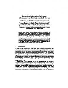
the existing AUTOSAR meta-model. However extension to the meta-model was necessary for the definition of the Application Replication View. The necessity of the extension has been the main reason for choosing UML as modeling language. UML offers extension mechanisms in form of profiles [4], which let us specialize UML general concepts to domain specific concepts. Domain specific concepts are represented as UML stereotypes that extend UML metamodel elements. The UML choice is further corroborated by the existence of a first standard version of a UML profile for AUTOSAR. This profile in this first version, however, does not cover yet all the AUTOSAR meta-model concepts. The proposed UML model-based approach is illustrated through a real case study. The paper is organized as follows: SectionII summarizes AUTOSAR methodology and presents its extension. Section III introduces part of AUTOSAR meta-mamodel that enables schedulability analysis at system level and related UML profile. Section IV presents needed replication characterization and extension to the AUTOSAR which enables to specify it. Section V presents an industrial case study, in order to show the applicability of our approach. Based on this, practical usage of specified UML profiles is presented by providing models for the case study. Replication assessment is presented through schedulability results. Interestingly, results suggest a refactoring of the software/hardware architecture. Section VI discusses related works and Section VII concludes the paper. II. AUTOSAR M ETHODOLOGY AND ITS EXTENSION TO R EPLICATION A SSESSMENT This section presents the AUTOSAR methodology first, then it explains how replication assessment is integrated in the methodology. A. AUTOSAR Methodology and Basic Models AUTOSAR specifies a methodology for the development of automotive system [2] (see Fig. 1). The development chain of this methodology stretches from the depiction of application software components to the runtime infrastructure, including the description of the hardware platform. According to Fig. 1 the methodology chain is specified through the following phases: • Vehicle Architecture Design: During this phase, the application is specified in terms of the software architecture: software components, interfaces, ports and connectors. The platform is specified in terms of hardware architecture: electronic control units (ECUs) and their interconnection topology, i.e. physical ECUs interconnection through buses or dedicated links.The mapping of software components on ECUs is not done during this phase, but constraints on this mapping can be specified at this level. The vehicle architecture design models are exchanged through an XML artifact called
AUTOSAR Methodology
Replication
Vehicule Architecture Design SWC 1
SWC 2
SWC 3
SWC 4
Re
ECU 3
s on ati
ECU 2
c pli
ECU 1
ECU 2
ECU 3
SWC3
SWC2
y
SWC4
Extract ECU Specific Information
ECU Configuration
t eg
ECU 1 SWC1
tra
System Configuration
ECU 1 SWC1
SWC4 RTE
Schedulability Analysis
ECU 1 SWC1
SWC4 RTE BSW
ECU Executable Generation
0110101100011 0101111100110 0000011100110 1010101010100 1101010110100 0001111011111
Figure 1. AUTOSAR methodology and its extenstion to Replication Assessment
•
•
•
System Configuration Input, which actually serves as input for the following phase. System Configuration: During this phase the mapping of the software architecture into the hardware architecture is performed. Software components are mapped into ECUs, and application messages are mapped into bus frames.Moreover the internal behavior of software components is also specified. Internal behavior is a specification of events (RTEEvents) and runnable entities. The latter are the smallest code-fragments provided by software components. The artifact to be produced at the end of this phase is called System Configuration Description, which serves as input for the following phase. ECU specific information extraction: During this phase information specific to each ECU is automatically extracted, and a first layer of RTE is automatically generated. The artifact to be produced at the end of this phase is called Extract of System Configuration Description, which serves as input for the following phase. ECU configuration: During this phase the basic services of the platform are configured on each ECU. The most important step lies in the specification of the mapping of runnable entities into OS tasks. The artifact to be produced at the end of this phase is the ECU Configuration Description. This artifact is used for the generation of binary code.
B. Methodology extension to Replication Assessment We envisage a replication assessment that starts with a set of software components identified as safety critical and for which software redundancy should be provided. Let us remark that the identification of safety critical software components is actually the output of safety analysis at system and software level. Our main objective is to analyze if redundancy injection can alter negatively schedulability properties
of the system. We assume that the system, before injecting redundancy, has already passed the schedulability test. The schedulability test verifies that the set of tasks executing system responses have enough computational resources to meet system deadlines. Tasks are characterized by their computational demand. System responses are chains of tasks activations triggered by external stimuli. External stimuli have to be characterized in terms of triggering pattern. At the heart of the tasks set definition, lies the AUTOSAR Application Timing View. For the definition of Application Timing View we will refer to the work of Anssi at al. [5]. It consists of an AUTOSAR model depicting event chains: chains of events referring to the activation and termination of runnables, that can span different software components. Event chains are subject to latency constraints between the occurrence of the first event (stimulus) and the last event of the chain (response). Even tough the Application Timing View does not belong to the standard AUTOSAR methodology, its definition can be completed using other two artifacts produced during the standard methodology: (1) the System Configuration Description that contains mapping of software components on ECUs defining computational demand for runnables, and (2) ECU configuration Description that contains the mapping of runnables on tasks. For replication injection, we need to declare at Vehicle Architecture Design level, the replication strategy to pursue for safety-critical components. This declaration covers different dimensions: type and number of faults to be tolerated, the replication style, and allocation of replicated components on ECUs. This declaration allows to generate the Replicated Software Architecture: the set of replicated components and replicated connections, along with possible dedicated components for replication management. Platform assumptions in terms of replica communication guarantees should now be declared. Section IV discusses these concepts in details. Replication strategy declaration and the replicated software architecture are organized in a so-called Application Replication View. The Application Timing View and the Application Replication View are the additional artifacts for the extended methodology. Once the two views are defined, schedulability analysis is applied on the redundant system (see Fig. 1). The replicated components are assumed to be replicated together with their internal runnables and executing tasks. Schedulability analysis is carried out on a set of tasks composed of application tasks and additional ad-hoc tasks injected by replication. Let us remark that given a replication strategy, the set of additional tasks to schedule, together with application tasks, strictly depends on platform properties. During schedulability analysis, different replication strategies may be tested and results may impact the Vehicle Architecture Level design as shown in the Case Study.
III. UML P ROFILE ENABLING SCHEDULABILITY ANALYSIS
In this section we present a UML-profile that covers AUTOSAR meta-model elements enabling schedulability analysis. These elements have been already identified in [5], and in our paper these elements form the Application Timing View. As original contribution of the paper these elements are formalized in the form of a UML profile. Elements covered by the presented UML profile are then: (i) elements for modeling software/hardware entities, (ii) elements for characterization of resource utilization and (iii) elements for the timing characterization of the application. In the following we will detail the AUTOSAR meta-model elements for the above-mentioned characterizations along with the related UML Profile. A. AUTOSAR concepts for the software, hardware and behavior modeling and related UML Profile The initial stage of AUTOSAR development chain corresponds to the application layer. Its fundamental part is the specification of software components, ports, interfaces and data elements. For the modeling of software entities SwComponentPrototype is used, typed with SwComponentType. For the purpose of communication, software components can have ports (PortPrototype) which are characterized by the interfaces (PortInterface). Following is vehicle’s physical system topology. According to AUTOSAR System Template [6] topology is formed by a number of ECU instances (ECUInstance describes the presence of an ECU in the vehicle) that are interconnected to each other in order to form ensembles of ECUs and communication clusters (CommunicationCluster), which are further detailed by providing information on bus-specific properties. Communication cluster provides the information about protocol name, protocol version and channels speed expressed in kbps. It aggregates one or more physical channels (PhysicalChannel) representing the communication medium. ECUInstance has one or more communication connectors (CommunicationConnector) which describes the bus interfaces of the ECUs and sending/receiving behavior. Next is the development of each application software component where the main part is the description of their internal behavior. Internal behavior describes the scheduling relevant aspects of a component, i.e. the runnable entities (RunnableEntity) and the events (RTEEvent). Furthermore, the behavior specifies which runnable responds to which event. However it does not describe the detailed functional behavior of the component. Table I summarizes all the concepts necessary to model software, hardware and behavior, together with related UML extensions for the purpose of creating the profile.
Table I UML EXTENSIONS FOR AUTOSAR
AUTOSAR Concept SwComponentType SwComponentPrototype PortPrototype PortInterface InternalBehavior RunnableEntity RTEEvent ECUInstance PhysicalChannel CommunicationConnector CommunicationCluster
UML extension Class Property Port Interface Activity Activity Event Property Connector Port Class
B. AUTOSAR concepts for the characterization of resource utilization and related UML Profile The characterization of resource utilization concerns two basic concepts, namely mapping of software components into hardware elements and mapping of runnable entities into specified operating system tasks. The former, according to the AUTOSAR methodology is part of the System Configuration Description. For the modeling purposes, SwcToEcuMapping meta-element is being used. It holds a reference to the ECU (ECUInstance) and a reference to all of those software component instances that will be mapped into this particular ECU. In our profile, this element extends the MARTE (Modeling and Analysis of Real-Time and Embedded Systems) [7] ”Assign” stereotype. Mapping of runnables into tasks is a result of ECU configuration phase. In general, ECU configuration may be depicted as a twofold process in which the first is specification of ECU Configuration Parameter Definition and the second is specification of ECU Configuration Value. ECU Configuration Definition declares how and what information will be presented whereas ECU Configuration Value holds the actual configuration. For the first part, there are existing AUTOSAR templates that define standard configuration descriptions, e.g. how to proceed with the definition of OS specification. However vendor might want to specify his own, specific ECU configuration parameters. This can be achieved thanks to the flexibility delivered by the meta-model for ECU configuration. Consequently specification of the tasks for each ECU is also a twofold process. The way to model the first part is ECU configuration module definition (EcucModuleDef ). For this element one has to define ECU parameter configuration container (EcucParamConfContainerDef ) named ”OsTask”. In the second step, the actual configuration takes place. This is done utilizing ECU module configuration value (EcucModuleConfigurationValues) for which we define ECU container values (EcucContainerValue). Each ECU container value in this case represents the task. This is specified by setting
its definition (property definition of EcucContainerValue) to previously defined container called ”OsTask”. Mapping of runnables into OS tasks is done indirectly. Tasks are correlated with events (RTEEvent) that trigger runnable entities. This modeling is also a two steps procedure. First, specification of ECU Configuration Parameter Definition consists of ECU module definition (EcucModuleDef ) named ”Rte”. To this module definition a container definition (EcucParamConfContainerDef ) called ”RteSwComponentInstance” is associated. The last aggregates another container called ”RteEventToTaskMapping” which allows referencing previously specified OS tasks and RTEEvents. As a second step ECU container values are being specified with their definitions being set to the containers created in the preceding step. Table II lists AUTOSAR concepts needed to configure ECU in terms of its OS tasks and mapping of runnables, together with UML elements that they extend. These meta-model elements have been used for the specification of design models of a case study presented in section V. These design models are compliant with the AUTOSAR methodology.
ECU ConfiguECU Configuration Parameration Values ter Definition
Table II UML EXTENSIONS FOR AUTOSAR E CU CONFIGURATION PROFILE
AUTOSAR Concept EcucModuleDef EcucParamConfContainerDef EcucReferenceDef EcucForeignReferenceDef EcucModuleConfigurationValues EcucContainerValue EcucReferenceValue EcucInstanceReferenceValue
UML extension
chains can be defined at different levels of granularity, in accordance with the T iming V iew concept of AUTOSAR. In this paper we are interested in SwcT iming V iew, in oder specify system responses and related deadlines. More in detail, SwcT iming V iew focuses on timing of software component internal behavior, i.e. the component’s behavioral decomposition into runnable entities executed at runtime. Timing description on this level may refer to the activation, start and termination of a runnable entity. This view is attached to the Component Internal Behavior Description of a software component, which belongs also to the System Configuration Description. Timing Extension extending UML elements is presented in Table III. These meta-model elements has been used for the definition of the Application Timing View of a case study presented in section V. This view represents an extension to the AUTOSAR methodology. Table III UML EXTENSIONS FOR AUTOSAR T IMING P ROFILE
AUTOSAR Timing Concept TimingExtension TimingConstraint TimingDescriptionEvent TimingDescriptionEventChain
UML extension Comment Comment TimeObservation InformationFlow
Class Class Property IV. UML P ROFILE ENABLING REPLICATION COST Property CHARACTERIZATION InstanceSpecification The specification of software redundancy in this paper has InstanceSpecification the objective of declaring the strategy the designer wants InstanceValue to follow for replication, considering all the aspects that InstanceValue
C. AUTOSAR concepts for the timing characterization of the applications and related UML Profile AUTOSAR Timing Extension [8] defines the meta-model elements that serve for timing characterization. The fundamental notion for the description of timing properties is the notion of event chain, specified through the T imingDescriptionEventChain element. A timing event chain expresses the temporal correlation between two observable timing events, namely stimulus and response, that have functional dependency. Timing events are specified through so-called T imingDescriptionEvent elements. Event chains can be built from sub eventchains (segments). Triggering behavior (e.g. periodic, sporadic, and arbitrary) of event chains are specified through EventT riggeringConstraint element that refer to the stimulus of the corresponding event chain. An event chain is used as the subject to attach a timing constraint, represented by LatencyT imingConstraint elements. Actually, event
can have an impact on schedulability analysis, i.e. type of failures to be tolerated, replication styles, replicas placement, platform properties. We assume that a replication strategy is applied on a software component, that will be entirely replicated, in terms of its internal runnables and executing tasks (defined in the ECU configuration). Executing tasks will be in the following called processes, to adopt the traditional notion of distributed model, in which the distributed system is abstracted to a set of communicating processes [9]. Processes, which thus execute components’ internal runnables, can be correct or f aulty. A correct process never fails, while a faulty process might eventually fail. If a process fails, then the application component is faulty as well. 1) Failures classes: The types of failures affecting the behavior of a faulty process have an impact on the cost of replication. In this paper we consider the types of failures according to the following classification: •
Arbitrary failures: a process is said to fail in an arbitrary manner if it deviates arbitrarily from its specification.
•
•
Also called Byzantine failures [10], these are the more severe failures and the most costly to tolerate. Omission failures: an omission failure occurs when the process does not send (or receive) a message it is supposed to send (or receive) according to its specification. Crash failures: a crash failure occurs when the process stops its execution prematurely.
In the literature so-called timing failures are considered as well. A timing failure occurs when a process does not execute its behavior in time according to the specification. Our response-time validation is actually performed in order to assure that system will be timing failure-free by construction. As not tolerated, timing failures will not be further discussed. 2) Replication Styles: Style of replication characterizes the way replicas are managed. Replicas management has the objective of computing correct results for the intended receivers, in spite of a threshold of faulty replicas. •
•
•
Active replication: in this case replicas process the same inputs. Replicas are assumed to be deterministic: the result of a behavior execution depends only on replicas initial state and of the sequence of executions already performed [11]. Replicas behave independently and mechanisms should be provided to ensure that all replicas receive the inputs in the same order to keep consistent the state of replicas. Passive replication: in this case only one replica (the primary) is responsible for the inputs processing [12]. The backups interact with the primary to receive the current primary state, before the next input will be processed. This replication style requires less resource utilization than active replication and makes no assumption on replicas determinism. However, in case of primary failure, the primary take-over increases response time. Semi-active replication: the semi-active replication style [12] was introduced to use the active approach with non deterministic replicas. Inputs are processed by all replicas (followers), while the leader will inform the followers about the current leader state.
3) Replicas Allocation: To fully specify the replication strategy for safety critical components, the initial number of replicas and the threshold on faulty replicas must be defined. At the same time, the mapping of replicas on hardware computing resources should be defined in order to determine resource utilization due to replication. Fig. 2 shows the UML profile for Replication that contains all the information aforementioned. This profile extends the OMG QoS and FT profile [13]. The ReplicationStrategy stereotype allows the declaration of critical software components to replicate. The replication strategy is characterized by the choices of the failure class, the replication style, the
initial number of replicas as well as the minimum number of replicas. Replicas allocation is modeled by the replicaHost property. Once the replication strategy is declared a replicated model applying these strategies can be generated. For each critical component, the replicated model contains the initial number of replicas on which the appropriate Replica stereotype is applied (ActiveReplica, PassiveReplica or SemiActiveReplica). Each replica has a reference to the initial component (component property) and knows all other replicas of the group (replicaGroup property).
Figure 2.
UML Stereotypes for Replication
4) Platform abstraction: It is well-known that the execution platform plays a predominant role when analyzing the incurred computational cost of software replication. The equivalence of the software replication problem, and more precisely the problem of keeping consistent the state of replicas, has been proved to be equivalent to the Consensus problem [14]. This means, for instance, that the problem is unsolvable in the case of crash failures in a so-called asynchronous system: a system in which no upper bounds can be established on (i) message delays (or number of message losses), (ii) relative speed of processes, (iii) clock drift rates [15]. On the other hand, the Consensus cost is less when the platform is assumed synchronous: a priori known bounds on message delays, relative speed of execution in different processors, and clock drift rate. Between the synchronous and the asynchronous models, a variety of intermediate
models have been defined in the literature, which make the consensus problem solvable with different costs. Choosing a platform model by quantifying and combining the different levels of synchrony on messages, processing and clocks, can be very difficult. As we focus on the replication, and not on the Consensus problem in general, we are able to model platform properties as communication primitives that can be assumed as provided by the platform. In particular, we are interested in guarantees provided by platform mechanisms to transfer data (the ”message”) from the sender to the set of receiving replicas. The communication primitives represent thus the basic building blocks to realize software replication [9]. The communication primitive must provide guarantees to the receiving processes. All correct receiving processes, for example, must deliver the sender’s message if the sender is also correct, if the so-called Validity property holds. A receiving process may deliver a special message, ”sender faulty”, if the sender failed (e.g. the primary), but either all correct processes will deliver ”sender faulty” or none will, if the so-called Agreement property holds. Other properties can be related to the order of messages, such as the Total Order and the FIFO Order. Properties are formally stated below: • Validity if the sender is correct and broadcasts a message m, then every correct process delivers m. • Integrity a process delivers a message m at most once, and if it delivers some message , then m was broadcast by the sender. • Agreement If a process delivers a message m, then all correct processes deliver m. • FIFO Order if a process broadcasts a message m1 before a message m2 , then any other process will deliver m1 before m2 . • Total Order if a process delivers a message m1 before a message m2 , then any other process will deliver m1 before m2 . The combination of Validity, Integrity, Agreement and Order properties, will characterize the specification of different broadcast communication primitives, as defined below: • Total Order Broadcast: Validity, Integrity, Total Order, Agreement • FIFO Broadcast: Validity, Integrity, FIFO Order, Agreement • Reliable Broadcast: Validity, Integrity, Agreement • Best-effort Broadcast: Validity, Integrity Let us just clarify that a platform that offers a total order, could be for instance a platform in which messages are sent by a pre-defined scheduling on timed slots and communication hardware implies that if a message is lost, then it is lost for all the intended receivers (which is not the case in a TCP/IP communication). Fig. 3 represents the communication platform abstraction. This abstraction is given in the form of a model library that
provides communication types that are usable by models. As stated above, we consider processes communicating by broadcast (1 sender, n receivers). The model library offers four broadcast communication types (TotalOrderBroadcast, FIFOBroadcast, ReliableBroadcast and BestEffortBroadcast). These broadcast communication types give send() and receive() services. These types are encoded by UML association classes that can be used to type UML connectors in a component model.
Figure 3.
UML Library for Broadcast Communication Abstractions
The usage of this profile is illustrated in section V in which the Application Replication View is defined. 5) The replication strategy’s impact on system schedulability: Once a given replication strategy has been injected, system schedulability must be verified. In particular, we are interested in analyzing the impact of application replicas and algorithms needed to manage the set of replicas, consisting in a set of additional tasks. The framework aims at easing the definition of the new tasks set to analyze, thanks to introduced platform communication abstractions. In the case of Active Replication and crash failures, for instance, the Total Order Broadcast as underlying platform property, reduces the replication assessment to the evaluation of only the computational demand of replicated application processes, as the Total Order Broadcast assures replicas consistency. In the primary-backup case, the primary failure detection can cost at application level the sending of only a ”primary faulty” message if FIFO broadcast is employed. The consensus for a new primary can cost at application level the only sending of a ”newprimary, primaryid ” if Total Order broadcast is assumed. If no sufficient communication properties are provided by the platform, additional tasks should be added to realize the needed communication guarantees at application level.
V. T HE CASE STUDY This paragraph presents in details cruise control system. It serves as a case study to practically apply the proposed methodology. The case study is actually the same as presented in [5]; for which system schedulability was shown. Based on this example we will introduce previously mentioned UML-profile constructs for the specification of software/hardware architecture and for the specification of the Application Timing View and Application Replication View. Having this information, schedulability analysis test will be performed on the replicated system. This is to show the influence of replication provision onto timing aspects of the system.
Figure 4.
Software architecture for Cruise Control System
Figure 5.
Hardware architecture for Cruise Control System
A. Cruise Control System Cruise Control System (CCS) responsibility is to maintain the speed of a car, regardless of whether the vehicle moves on a flat or a slope surface. Physical setup of CCS consists of two or three ECUs, depending on implementation (not including redundant control units). In our case, hardware architecture is built from two ECUs, the Body Controller and Engine Management ECU. Communication between them is via the CAN (Controller Area Network) bus. There are eight elementary functions distributed over those two ECUs. Table IV presents them. Table IV BASIC FUNCTIONS OF C RUISE C ONTROL S YSTEM
Function Input acquisition Input interpretation Diagnosis Limp home Speed setpoint Application condition and basic function Controller
Description Acquires the sensor data Interprets the acquired sensors data to determine drivers desire Detects errors and inconsistencies in acquired data Decides which action to take in case of detected error Calculates the speed setpoint desired by the driver Calculates cruise control states and transitions to decide whether to carry specific cruise control activities Maintains the vehicle speed
B. AUTOSAR Standard Models for Cruise Control System According to AUTOSAR methodology (Section II), system design begins with definition of software components, interfaces, ports and connectors. In terms of cruise control system, these notions are depicted in Fig. 4. As it can be seen, software architecture consists of two software components, Body Controller and Engine Management software component. First of them manages data coming from sensors through input SensorsData port. As an output it provides data to the second software component. Engine management software component computes throttle torque and transmits this data through ThrottleTorque port to the throttle actuator.
Its second responsibility is to provide information about action that should be undertaken in case system undergoes disruption (DiagnosisAction port). Both components are encapsulated in composite software component called CruiseControlApplication. In parallel, specification of a system topology takes place in this stage of methodology. Fig. 5 adduces topology with two ECUs (ECUInstance). They are communicating via CAN physical channel (CanPhysicalChannel) which is part of the CAN cluster (CanCluster). Topology serves as constraints for the mapping of software components. Next specification level in the AUTOSAR methodology, System Configuration Description includes models defining mapping of software components into ECUs. Fig. 9 exhibit mapping in which bodyControllerSWC has been deployed into bodyControllerECU and engineManagementSWC is executed on engineManagementECU. The last is ECU Configuration Description that provides information about OS tasks and mapping of runnable entities into them. Section III-B shows exactly how to configure the ECU. The model itself consists of two parts: the definition of ECU Configuration Parameter Definition and specific configuration, i.e. ECU Configuration Value. In our case, in the first place definitions of the OS and Rte (Runtime environment) configuration were modeled, then in a second place concrete configurations for Body Controller and Engine Management ECUs based on former definitions are modeled. For instance configuration values, corresponding to the OS configuration definition for the Body Controller ECU, are Acquisition and Failure Management tasks. Rte configuration definition contains information on how to proceed with mapping of runnable entities into OS tasks. According to that, configuration values for mapping were specified,
Figure 6. tasks
Mapping of Input Acquisition runnable entity into Acquisition
Table V T IMING CHARACTERISTICS OF RUNNABLE ENTITIES AND THEIR ALLOCATION TO THE TASKS
Task priority
Runnable
WCET (ms)
Period (ms)
Allocated to task
Input Acquisition Input Interpretation
2.5 2.32
10 40
Acquisition 1
Diagnosis
1.52
10
Speed Setpoint Limp Home Application Condition Basic Function Controller
1.03 3.5
10 40
3.92
40
2.08 1.4
40 40
Failure Management Setpoint Control
2 2 3
e.g. ”InputAcquisitionRunnableToAcquisitionTask” visible in Fig. 6 corresponds to the mapping of Input Acquisition runnable entity into Acquisition task. Table V lists all the tasks, including those of Engine Management ECU OS, together with the assignment of runnable entities. C. Application Timing View for Cruise Control System In order to complement the system specification with timing information, UML profile for AUTOSAR Timing Extension has been used (presented in section III-C). The SwcTiming view has been introduced to characterize timing properties of runnable entities and latency constraints between them. The initial concern is the enforcement of latency constraint on end-to-end scenarios. We are differing two action flows, computation of throttle torque and fault diagnosis. In AUTOSAR Timing Extension, flows are represented by timing chains (TimingDescriptionEventChain). Timing chain called ”ThrottleTorqueComputationFlow” corresponds to the first flow. The second one is defined by ”DiagnosisFlow”. Each of these chains have the stimulus and the response which in the case of SwcTiming refers to the runnable entities. Timing chains can contain sub-chains therefore we are able to reference all the intermediary runnable entities that participate in obtaining the result for specific end-to-end flow. Computations within the first flow are performed by the following sequence of runnables: Input Acquisition, Input Interpretation, Speed Setpoint, Application Condition, Basic Function and Controller. ”DiagnosisFlow” timing chain is constituted only by the Diagnosis which is a stimuli and the
Figure 7. Latency constraint imposed on the computation of throttle torque
Limp Home as a response. Relevant from the schedulability point of view is the possibility to impose latency constraints on the timing chains. ”ThrottleTorqueComputationFlow” has assigned latency constraint of 500ms (see Fig. 7). The stimulus event of this scenario is called SensorsDataAcquired and modeled as a timing observation. The stereotype of this event is TDEventSwcInternalBehavior. It relates to Input Acquisition runnable entity and its activation. Response of this timing chain is an event called ThrottleTorqueComputed which references the runnable called Controller and represents its termination. The fact that the presented model concerns software components timing view is represented by the UML Comment stereotyped with SwcTiming. Comment itself is linked to ”CruiseControlApplication” composite software component to express the scope of this timing specification. In a similar way was imposed latency constraint of 100ms on the chain referring to fault diagnosis scenario. The last, in terms of timing specification is model presented in Fig. 8. This model adds information about periodicity of runnables, necessary to perform schedulability analysis. Results of this analysis can be then compared with previously imposed latency constraints. For instance period of an event that triggers runnable called diagnosis, should be equal to 10ms. Table V contains specification of internal timing characteristics also for the second software component (EngineManagementSWC) as well as mapping of runnable entities into OS tasks. D. Schedulability of the Cruise Control System In [5] schedulability results for the non-replicated CSS were obtained using the so-called offset based technique [16] for distributed systems implemented in MAST1 tool. It revealed that the system is schedulable. Results also show how much capacity is available until the system becomes unschedulable by providing the values for slack2 . Resources 1 MAST
tool - http://mast.unican.es/ - the percentage by which we can increase computational demand of tasks executed by the processing resource without jeopardizing schedulability. The slack in MAST is calculated by modifying the worstcase execution times and repeating the analysis using a binary search to find the point in which the system becomes unschedulable (or schedulable if it wasn’t) [17]. It is calculated with a 1% precision to limit the amount of times the analysis is repeated to around 20 times. 2 Slack
providing FIFO Reliable Broadcast 3 , replica determinism is assured as the order of input messages will be the same for the two replicated runnables, all the time. This implies that for the specified Replication Strategy incurred replication overhead is uniquely due to computational demand of task replicas. No other ad-hoc components are needed for replica management, no other additional tasks should then be considered for schedulability.
Figure 8.
SwcTiming view for Body Controller SWC
slack results were: for EngineManagementECU equal to 71.20%, for BodyControllerECU equal to 205.25%, for CAN bus equal to 629.14%. Worst-case response times were: for DiagnosisFlow equal to 10.95 < 100 and forTrottleTorqueComputationFlow equal to 59.29 < 500. Figure 9. Replication Strategy for engineManagement application component prototype
E. Application Replication View for Cruise Control System The safety critical component to make redundant for the case study is the EngineManagementSWC software component, which actually encapsulates the throttle control function. The replication strategy we want to evaluate for our system considers: the active replication style, two initial component replicas, a threshold of one replica’s crash failure. This is actually a very simple case that represents a good starting point for the schedulability evaluation. Fig. 9 shows the Replication Strategy as declared by the designer using the stereotypes introduced in Section IV. The deployment of replicas considers the replicas as allocated on the BodyControllerECU. The Replicated Architecture is shown in Figure 10. Let us note that the replication of a component means that the tasks set, as configured in the nonredundant component, is replicated as is in the replicated component. More in detail we have the Control Task and the Setpoint Task replicated in the BodyControllerECU. The Control Task executes the Limp Home runnable, which consumes data from a single producer, i.e. the runnable Diagnosis executed by the FailureManagement Task. The Control Task executes the runnables Application Condition, Basic Function, Controller, which consume data from a single producer, i.e. the speedSetPoint runnable executed by the Setpoint Task. The speedSetPoint runnable executed by the Setpoint Task consumes date from a single producer: the runnable InputInterpretation, executed by the Acquisition task. Each group of replicated runnables have thus only one producer of data. By setting the platform properties as
Figure 10.
Replicated architecture
F. Schedulability of the Replicated Architecture Contrarily to the case treated in [5], the system architecture here boils down to a tasks set not analyzable by the offset based technique. The offset based test is able to test a set of chains of dependent tasks in a distributed system. However, the test assumes linear chains: each external 3 Considering the underlying communication bus a CAN bus, we can make the assumption that messages are not lost. We believe that this assumption makes sense in general in the automotive communication platforms
event triggers a unique linear chain of dependent tasks, subject to a global deadline. In our replicated architecture the linear chains hypothesis does not hold anymore. Event chains now have a replicated segment constituted by all tasks whose mapped runnnables belong to replicated EngineControlSWC, in turn allocated to BodyControllerECU. Originally linear, each chain triggered by a single external stimulus, has now a fork towards two segments, representing the replicated parallel processing. In order to deal with this case, we applied techniques depicted in [18] to obtain a set of linear chains from non-linear ones. The idea is to consider for each fork, two different configurations, one for one branch and one for the other branch. Schedulability of all the configurations, each of them satisfying the linear chain hypothesis, must be verified. Let us note that in our case the most critical configuration is the one in which a) in the ThrottleTorqueComputationFlow, the Control task and the Setpoint Task run on the BodyControllerECU and b) in the DiagnosisFlow the Control Task (for Limp Home runnable) run on the BodyControllerECU. In the BodyControllerECU run also the Acquisition and Failure Management tasks as in the non-replicated architecture. Schedulability results have been then obtained using MAST tool and the offset based technique on a set of four linear configurations. The worst-case results are given below: Resource utilization for the BodyControllerECU, that now is in charge of executing the set of replicated tasks (replica of Control Task, replica of Setpoint Task) has been computed as first. Unfortunately, this configuration exceeds the capacity of the BodyControllerECU of 18.75%. We tried then two different alternatives. Alternative 1: a more powerful BodyController ECU: We tried to augment the speed factor of the BodyControllerECU to 1.5, which means reducing by 30% worst case execution times of the runnables executing on BodyControllerECU. In this case the system is schedulable. Processors slack for BodyControllerECU is now equal to 22.35%. Worst case response times for DiagnosisFlow is equal to 6.6 < 100 and for TrottleTorqueComputationFlow equal to 61.178 < 500. Alternative 2: Change of the software architecture: The EnergyManagementSWC is split in two different software components: one software component encapsulating the Setpoint runnable and another software component replicated on the BodyControllerECU, encapsulating the LimpHome, ApplicationCondition, BasicFunction, and Controller runnables all allocated to Control Task. Obtained worst case response times are: for DiagnosisFlow 18.8 < 100 and for TrottleTorqueComputationFlow 83.383 < 500. Other alternatives can be considered, but for the purpose of the paper, this simple analysis already shows how redundancy can affect system schedulabilty and that schedulability and replication considerations can lead to the refactoring of the system architecture at vehicle design level. Interestingly,
analysis results are also related to the size of software components, which should be small to easily place replicas by exploiting residual computational capacity of existing resources. Small component size is also a desirable property from ISO26262. VI. R ELATED WORK Safety requirements in real-time systems are typically addressed by middlewrare-level fault-tolerance mechanisms [19][20][12]. In the automotive domain, time-triggered architectures (TTA) [21] have been extensively employed. TTAs guarantee components to be fault-tolerant through the use of active replication, dedicated hardware, and the use of two redundant real-time networks based on the time division multiple access. In general, these approaches have internal implementations of fault-tolerant mechanisms that affect system schedulability. In the case of a TTA platform, for instance, the application must be designed such that the time interval between writes and reads on two connected components ports is long enough to perform the fault-tolerance functions. This platform constraint makes critical the decision on how much redundancy to inject, as the redundancy may impact the existence of a scheduling respecting system deadlines. [22] presents an approach for the timing validation of time-triggered architectures once specific-platform fault-tolerance mechanisms have been injected. The approach considers the injection of active replication and crash failures in a data flow. The existence of an off-line schedule on the fault-tolerant data flow proves the correctness of the system. Differently from [22], our methodology supports schedulability predictions based on fixed-priority schedulers, in compliance with the AUTOSAR OS specification. Moreover, our methodology supports a schedulability analysis based on system end-toend responses, in which tasks activation is event-driven. This asynchronous paradigm is well suited for early assessment at design level and it is supported by AUTOSAR OS. As for profiles we thoroughly studied standard existing profiles for the definition of timing/replication concepts, in particular MARTE and QoS and FT profiles. MARTE was defined to provide the community of RTES designers and developers with a common reference modeling standard. It completes and redefines previous SPT profile (UML Profile for Schedulability, Performance and Time). MARTE provides UML extensions for system modeling (including hardware/software resources) of RTES according to MDA paradigm. Recently, MARTE has been recommended in the Genesys project as means to specify timing constraints and allocation issues [23]. In our approach we have specialized MARTE Assign concept to model the AUTOSAR SwcToEcuMapping. For timing description, we have adopted MARTE philosophy by specializing UML TimeObservations for the modeling of AUTOSAR TimingDescriptionEvents. These specialized UML TimeObservations are then used for
the specification of timing constraints like latencies. The QoS and FT profile [13] covered a large spectrum of issues traditionally covered by the dependability domain [24]. It provided a framework to support risk assessment and FT mitigation solutions modeling. Risk assessment is used for system level safety issues while mitigation solutions are used to specify implementation solutions according to safety requirements. The UML extension for replication presented in our approach is inspired from FT mitigation solutions modeling. In fact it only adds to this profile the capability to declare the failure classes and the allocation of replicas on execution nodes for each identified critical software component. A model-driven framework to allow the specification and the deployment of fault-tolerance mechanismls has been proposed in [25]. The framework allows the specification of fault-tolerant needs at application design level. By using fault-tolerance replication patterns, devoted middleware is automatically deployed and configured. The framework does not handle AUTOSAR design, but proposes a general UML methodology. Moreover, fault-tolerance provisioning is not assessed from a schedulability point of view.
[10]
VII. C ONCLUSION AND F UTURE W ORK
[16]
The paper presented a methodological framework for replication assessment of AUTOSAR applications. Different replication strategies may be injected in the system and schedulability analysis is employed to validate the feasibility of the chosen strategy. The framework is based on the AUTOSAR methodology and proposed an AUTOSAR extension both to the methodology and to the meta-model. The methodology has been extended by adding two additional views, an Application Timing View and an Application Replication View. The meta-model extension has been provided by defining a UML profile. This work combines results and methods developed in different software engineering disciplines (i.e. component-based approaches, schedulability analysis, fault tolerance and distributed systems) using models as an integration base. As future work, we will address (1) the automatic generation of the tasks set to schedule, upon replication injection and (2) the automatic deployment of middleware devoted to realize assessed replication mechanisms. Methodology extension to the synchronous paradigm to support development of time-triggered architectures will be considered as well.
[6] [7] [8] [9]
[11] [12] [13] [14] [15]
[17]
[18]
[19] [20] [21]
[22]
[23] [24]
R EFERENCES [1] AUTOSAR 4.0 (Automotive Open System Architecture) Specifications. [Online]. Available: http://www.autosar.org [2] AUTOSAR Methodology, AUTOSAR Std. [Online]. Available: http://www.autosar.org/download/AUTOSARMethodology.pdf [3] International Standards Organization, ISO/DIS 26262:2009 - Draft International Standard Road Vehicles - Functional Safety”, http: //www.iso.org, Std. [4] Unified Modeling Language Superstructure v2.3, OMG Std. [5] S. Anssi, S. Tucci-Piergiovanni, S. Kuntz, S. Gerard, and F. Terrier, “Enabling scheduling analysis for autosar systems,” in
[25]
Object/Component/Service-Oriented Real-Time Distributed Computing (ISORC), 2011 14th IEEE International Symposium on, march 2011, pp. 152 –159. “Autosar system template,” AUTOSAR. [Online]. Available: http://www.autosar.org/download/R4.0/AUTOSAR TPS SystemTemplate.pdf UML Profile for MARTE: Modeling and Analysis of Real-Time Embedded Systems, Version 1.1, formal/2010-08-32, OMG, November 2010. [Online]. Available: http://www.omgmarte.org/ AUTOSAR Specification of Timing Extensions, AUTOSAR Std. [Online]. Available: http://www.autosar.org/download/R4.0/ AUTOSAR TPS TimingExtensions.pdf R. Guerraoui and L. Rodrigues, Introduction to Reliable Distributed Programming. Springer, 2006. L. Lamport, R. Shostak, and M. Pease, “The byzantine generals problem,” ACM Trans. Program. Lang. Syst., vol. 4, pp. 382–401, July 1982. F. B. Schneider, Replication management using the state-machine approach. New York, NY, USA: ACM Press/Addison-Wesley Publishing Co., 1993, pp. 169–197. D. Powell, Delta-4, a generic architecture for dependable distributed computing, ser. Research reports ESPRIT. Springer-Verlag, 1991. “UML Profile for Modeling QoS and FT Characteristics and Mechanisms v1.1,” Object Management Group, Tech. Rep., Apr. 2008. T. D. Chandra and S. Toueg, “Unreliable failure detectors for reliable distributed systems,” J. ACM, vol. 43, pp. 225–267, March 1996. M. J. Fischer, N. A. Lynch, and M. S. Paterson, “Impossibility of distributed consensus with one faulty process,” in Proceedings of the 2nd ACM SIGACT-SIGMOD symposium on Principles of database systems, ser. PODS ’83. New York, NY, USA: ACM, 1983, pp. 1–7. J. C. P. Guti´errez and M. G. Harbour, “Schedulability analysis for tasks with static and dynamic offsets,” in IEEE Real-Time Systems Symposium, 1998. M. G. Harbour, J. C. P. Guti´errez, J. J. G. Garcia, and J. M. R. Concepci´on, Modelling and Analysis Suite for Real Time Applications (MAST 1.4.0), Grupo de Computadores y Tiempo Real Universidad de Cantabria, 2011. [Online]. Available: http://mast.unican.es/mast analysis techniques.pdf J. Garcia, J. Gutierrez, and M. Harbour, “Schedulability analysis of distributed hard real-time systems with multiple-event synchronization,” in Real-Time Systems, 2000. Euromicro RTS 2000. 12th Euromicro Conference on, 2000, pp. 15 –24. D. Powell, A Generic fault-tolerant architecture for real-time dependable systems. Kluwer Academic Publishers, 2001. Kopetz, Damm, Koza, Mulazzani, Schwabl, Senft, and Zainlinger, “Distributed fault-tolerant real-time systems: the mars approach,” IEEE Micro 9,, no. 1, pp. 25–40, 1989. G. Heiner and T. Thurner, “Time-triggered architecture for safetyrelated distributed real-time systems in transportation systems,” in Proceedings of the The Twenty-Eighth Annual International Symposium on Fault-Tolerant Computing, ser. FTCS ’98. Washington, DC, USA: IEEE Computer Society, 1998, pp. 402–432. C. Pinello, L. Carloni, and A. Sangiovanni-Vincentelli, “Fault-tolerant distributed deployment of embedded control software,” ComputerAided Design of Integrated Circuits and Systems, IEEE Transactions on, vol. 27, no. 5, pp. 906 –919, may 2008. G. Project, GENESYS: A Candidate for an ARTEMIS Cross-Domain Reference Architecture for Embedded Systems, H. R. Obermaisser, Ed., 2009. A. Avizienis, J.-C. Laprie, B. Randell, and C. Landwehr, “Basic concepts and taxonomy of dependable and secure computing,” IEEE Trans. Dependable Secur. Comput., vol. 1, pp. 11–33, January 2004. [Online]. Available: http://dx.doi.org/10.1109/TDSC.2004.2 B. Hamid, A. Radermacher, P. Vanuxeem, A. Lanusse, and S. Gerard, “A fault-tolerance framework for distributed component systems,” in Proceedings of the 2008 34th Euromicro Conference Software Engineering and Advanced Applications, ser. SEAA ’08. Washington, DC, USA: IEEE Computer Society, 2008, pp. 84–91. [Online]. Available: http://dx.doi.org/10.1109/SEAA.2008.50