A Traceability Approach for i* and UML Models Gilberto A. A. Cysneiros Filho
[email protected]
Andrea Zisman
[email protected]
George Spanoudakis
[email protected]
Software Engineering Group Department of Computing, City University Northampton Square, EC1V OHB, UK +44 (0)20 7040 8346
ABSTRACT
1. INTRODUCTION
In this paper we propose an approach that can be used to generate traceability relations between organisational models specified in i* and software systems models represented in UML (in particular use case and class diagrams). Our approach proposes different types of traceability relationships between i* and UML models and uses traceability rules to generate the different types of traceability relations between them. The traceability rules and traceable models are represented in XML. This makes possible the use of our approach in settings where the models are created and managed autonomously. The approach is supported by a prototype tool that interprets the rules and generates traceability relations.
The lack of understanding of the goals and objectives of an organisation by software developers implementing software systems for the organisation may result in systems which do not fit well with organisational practices or which fail to support effectively all the expected organisational activities. To address this problem, researchers have proposed numerous organisational modelling techniques [12][17][19][20][32], which can be used to specify models of the goals, structures and processes of organisations. Such models can be used to assist stakeholders and developers to develop a common understanding of an organisation and, therefore, facilitate the identification of requirements for systems that are developed to support its function [17]. As suggested in [12], if the requirement specification of a software system that is to be deployed in an organisation is based on a model of this organisation, then it becomes easier to guarantee that the system will assist the business in a more appropriate way.
Categories and Subject Descriptors D.2.1 [Software Engineering]: Requirements/Specifications methodologies D.2.2 [Software Engineering]: Design Tools and Techniques object-oriented design methods D.2.7 [Software Engineering]: Distribution, Maintenance and Enhancement - documentation D.2.10 [Software Engineering]: Design – methodologies, representation
General Terms Documentation, design.
Keywords Requirements engineering, traceability, organisational models, system models, XML.
Furthermore, as organisational models contain organisational knowledge elicited during the requirements acquisition process they can facilitate the understanding of the requirements specifications by “naïve” users [19]. The widely used object-oriented software system modelling techniques such as UML [28] are effective in specifying “what” a system does and “how” it does it. However, they are not as effective when it comes to the specification of the “why” behind the “what” and the “how” or, equivalently the motivation and rationale underpinning the functional and other requirements of a system [33]. This gap can be filled by organisational modelling techniques which adopt a goal-oriented approach to requirement specification (e.g. [2][9][21][32]) and as such they can be effectively used to describe the motivation and rationale that underlie software system requirements (“why”). It has to be appreciated, however, that in contexts where both such techniques are used it is also necessary to establish and maintain appropriate traceability relationships between the different kind of models that they generate. In such contexts, traceability relations can be used to: (a) ensure compliance between goals and software requirements specifications, reduce the risk of inconsistencies, and minimise the non-propagation of changes across different artefacts [1], (b) provide justifications for system requirements [27], and (c) establish the impact of
changes in the requirements specification of a system to an organisation and vice versa. Thus, the establishment and maintenance of such relations is an important factor for efficient software project management and software systems quality [1][2][9][14][21][26][27]. For an extensive and up to date survey of different approaches of relating goals with other elements in requirements specifications see [21]. However, despite its importance, (semi-)automatic support for traceability in existing software engineering environments and tools is still in its infancy. This inability to automatically identify and maintain traceability relations is due to the fact that the artefacts are independently created by non-interoperable tools, evolve autonomously, and often contain parts that have ambiguous meaning. As a consequence, traceability relations are established and maintained manually, which can be a time consuming and complex task. In this paper we propose (a) a set of traceability relations between organisational models expressed in i* and use-case and class models of software systems expressed in UML and (b) an approach for generating them automatically. i* [32] is a goaloriented organisational modelling technique that can be used to specify the actors and the goals of an organisation, the strategic relationships between these actors, and the relationships between the goals and the actions of these actors (a detailed description of i* model is beyond the scope of this paper and can be found in [32]).
The different types of traceability relations proposed in this paper are based on previous work of the first of its authors that was concerned with the development of guidelines on how to map organisational requirements represented in i* onto UML class models [5][6]. The overall approach to the automatic generation of the proposed relations is based on a rule-based approach for generating traceability relationships between requirements models expressed in natural language and UML class models that has been developed by the other two authors of the paper [35][36]. The remainder of the paper is structured as follows. In Section 2, we present examples of i* and UML use case and class diagrams that will be used throughout the paper. In Section 3 we discuss different types of relations between i* and UML use cases and class diagram. In Section 4 we present our traceability approach and give examples of traceability rules. In Section 5 we discuss some related work. Finally, in section 6 we summarise our approach and discuss directions for future work.
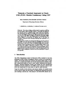
2. Models Figure 1 shows part of an i* model for a BookStore that sells books and CDs (product), adapted from [7]. This bookstore provides a web-based selling channel from which customers can buy its product on the web. This is presented in Figure 1 by the expanded actor WebStore.
Figure 1: i* model for a bookstore
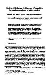
Other actors in the model are: Customer − the person who buys products from BookStore; Shopkeeper − the person who is responsible for carrying on business in the shop; System Administrator − the person who manages the webbased system; Card Processing Company − an external organisation that processes credit card transactions on behalf of BookStore; Inventory − a system that manages the inventory of the store; Shipment Company − a company that delivers products purchased by customers; and Dispatcher − a person responsible for the dispatch of the product. Figure 2 shows the UML use case and class diagrams for the web-base (WebStore) system.
CloserOrder Log On User
Search by Criteria Log On User
User Browse Products
UpdateCustomer Customer
Dispatcher Manage Basket System Administrator
Create New Customer Checkout
ShopKeeper
some important and relevant cases. These relations have been identified by taking into consideration the semantics of i* and UML models, and analysing different instances of these models.
Type 1: Overlaps between i* actors and use-case actors According to [32], actors in i* are active entities that execute actions to achieve certain goals, and have motivations, intents, and rationales behind the actions. These actors can represent a human, roles of a person, or a system. In UML use-case models [17], actors represent roles that a person, hardware device, or even another system plays with a system. Each i* actor is a potential system actor, if it directly interacts with the system under development. Therefore, actors in i* can be associated to actors in use-cases by an overlap relation which have the same or a lexically similar name with them. In our approach, a name n1 is considered to be lexically similar to a name n2 if and only if n1 is included in n2 and n2 does not incorporate any alphabet letters, which are considered to be semantically significant characters. In the models shown in Figures 1 and 2, the actor WebStore represents the system being designed. The actors System Administrator, Shopkeeper, Credit Card Processing Company, Dispatcher, Customer, and Inventory in the i* model are also represented as actors in the use case diagram. Thus, they can be associated by overlap relations with them. Note that BookStore is an actor in the i* model which is not represented in the use case. This is due to the fact that BookStore does not interact directly with WebStore system. However, it is not possible to conclude this from the model, since i* is proposed as a way of representing dependencies and not interactions.
Manage Catalogue Manage System
Card Processing Company WebStore
Product Catalog + + + + + + +
browseCatalogue() deleteProduct() addProduct() searchByCriteria() checkAvailability() editProduct() findProducts()
Product
Book
Order Manager
Item
CD
+ + + + + +
findOrder() validateOrder() displayOrders() acceptOrder() closeOrder() confirmOrder()
Order - number - dateShipment - trackingNumber
Inventory
Customer Manager + + + + +
findCustomer() addCustomer() deleteCustomer() editCustomer() logOn()
Customer - name - address - email - phone
Credit Card - nameOnCard - cardType - cardNumber
Type 2: Overlaps between i* actors and UML classes i* actors may also be related with UML classes as the latter describe a set of distinct objects (person, place, thing, and concept) in a system. Our criterion for creating such relationships is that the actor and the class involved must have the same or lexically similar names. Such relations can be created between the classes WebStore and Customer in Figure 2 and the actors with the same names in Figure 1. Note that in some cases it is also possible to relate i* actors with UML packages. In our example we do not find this situation.
Type 3: Overlaps between i* resources and UML classes Resources in i* are physical or informational entities. Thus, they can be related to classes in UML class diagram. Examples of such relations are those between the resources Item, Product and CreditCard and the classes with the same names in the class diagram of Figure 2.
Type 4: Overlaps between i* tasks and UML operations Figure 2: Use case and class diagram for WebStore system
3. TYPES OF RELATIONS In this section, we present the different types of relations that we have identified for i* models and use cases and class diagrams. These relations are not exhaustive, but we believe they cover
In i*, tasks represent activities that an actor executes. In UML, operations are defined as the implementation of a service that can be requested from a class (object) [17]. Thus, tasks in i* can be associated to operations in UML classes. Our criterion for creating such relations is that the relevant task and operation must have the same or lexically similar names. It is also possible to create such relations in cases where the name of a UML operation together with the name of the class that defines this
operation is the same as, or lexically similar, to the name of the task in i*. Examples of such relations can be generated between the task Search by Criteria and the operation searchByCriteria() in the class Product Catalog, and between the task Confirm Order and operation confirmOrder() in class Order Manager.
Table 1 : Relations between models SD
Goals in i* represent conditions or states of affairs in the world that an actor would like to achieve. Different from tasks, in i* it is not possible to specify how a goal is to be achieved, allowing alternatives to be considered. A goal can be either a business goal or a system goal. A business goal expresses goals regarding the business or state of the business affairs the individual or organisation wishes to achieve. System goal expresses goals that the system supporting the organisation should achieve. Normally, system goals describe the functional requirements of the system. Similarly to tasks, goals in i* can be associated to operations in UML class diagram that have the same name, have lexically similar names, or have a name composed by the name of the operation together with the name of the class that contains the operation. An example of the situation above is found with the goal Find Product and operation findProducts() in class Product Catalog.
--
Customer
Actor
Class
WebStore
--
--
BookStore
--
--
Inventory
Actor
--
Shipment Company
--
--
Dispatcher
Actor
--
Shopkeeper
Actor
--
Product
--
Class
CreditCard
--
Class
Manage Catalogue
Use Case
--
Order Products
--
--
Manage System
Use Case
--
Process Internet Orders Close Order Accept Order
SR Item
In UML, use cases specify a sequence of actions that the system can perform which produce a result to an actor. Thus, goals in i* may be related to use cases that have the same name or lexically similar names. In Figures 1 and 2 such relations can be created between the goals and use cases called Manage Catalogue and Manage System.
CheckOut
Similarly to relationships of Type 6, UML use cases can be associated by overlap relations with tasks in i*. Our criterion for the creation of such relations is that the relevant tasks and usecases must have the same name or lexically similar names. In the example models shown in Figures 1 and 2 the tasks Check Out, Search by Criteria, Close Order, Browse Products and Log On overlap with the UML use cases that have these names. Table 1 presents the possible relationships that exist between the models shown in Figures 1 and 2 for the elements composing the Strategic Dependency Model (SD) and the Rational Dependency Model (SR) [32]. Note that i* methodology does not differentiate between actors representing humans and systems. Therefore, it is difficult to identify the actors that represent the system being modelled. In addition, the i* actors can be related to actors in UML use case or classes, as shown in the table. Another issue is concerned with the fact that goals and tasks in i* represent dependencies that are realised by sub-elements in the Rational Dependency Model (SR). Sometimes it is not possible to find direct relations between these goals and tasks with elements in the use case and class models. Examples of this situation are found in Identify Customer, Automatic Log, FindProduct, BuyProducts, UpdateCatalogue, RunShop, and CheckAvailability.
Class
Actor
Type 6: Overlaps between i* goals and UML use-cases
Type 7: Overlaps between i* tasks and UML use-cases
Class Model
Actor
Card Processing Company
Type 5: Overlaps between i*_goals and UML_operations
Use Case Model
System Administrator
--
--
Use Case
Operation
--
Operation
--
--
--
Class
Use Case
Operation
Identify Customer
--
--
Automatic Log
--
--
Use Case
Operation
Log On FindProduct
--
--
BrowseCatologue
Use Case
Operation
SearchByCriteria
Use Case
Operation
--
--
BuyProducts Manage Basket
Use Case
--
Manage System
Use Case
--
Confirm Order
--
Operation
UpdateCatalogue
--
--
RunShop
--
--
Check Availability
--
--
4. TRACEABILITY APPROACH We propose a light-weight XML-based approach to generate bidirectional traceability relations between i* models and UML use cases and class diagrams. The approach is based on the use of traceability rules expressing the different types of relations presented in Section 3. The rules are represented in the XML based mark-up language1 that we have proposed in [35] [36].
1
A complete presentation of the DTD for this mark-up language is beyond the scope of this paper, but available upon request.
The use of XML [4] provides open and standard ways of expressing traceability rules, allows the construction of a simple rule interpreter, and facilitates access to and modification of XML documents.
the first part that must be generated when the conditions of the second part are satisfied.
Figure 3 presents an overview of the process of our approach. Initially, the i* model and UML diagrams are converted into eXtensible Markup Language (XML) documents [4] (i*.xml and UML.xml in the figure), following the GRL [15] and XMI [24] format, respectively, and using existing commercial exporters (e.g. ArgoUML [3], Unisys XMI exporter for Rational Rose [31] and OME exporter [15]).
IF Exists
Rule 1: in i*.xml; in UML.xml Such that EQUAL_TO(NAME(),NAME()) or LEXICALLY_EQUIVALENT(NAME(), NAME()) Generate Relation TRACE(,)
i*.GRL
Rule 2: UML.mdl
IF Exists in i*.xml;
OME XML Conversion
in UML.xml
XMI Generation
Such that EQUAL_TO(NAME(),NAME()) or LEXICALLY_EQUIVALENT(NAME(), NAME())
i*.xml
UML.xml
Generate Relation TRACE(,)
Rule 4: IF Exists
traceability
TraceRules.xml
in i*.xml; in UML..xml
relations
Such that
generator i*_UML_Rel.xml
EQUAL_TO(NAME(),NAME()) or LEXICALLY_EQUIVALENT(NAME(), NAME()) or (CONTAINS(NAME(), NAME()) and
Figure 3: Overall traceability process In the next step, i*.xml and UML.xml are matched with each other based on the traceability rules represented in TraceRules.xml document and using the traceability relations generator. The result of the matching process is a set of traceability relations also represented in XML as XLink [11] elements (i*_UML_Rel.xml). In Figure 4 we present examples of the traceability rules used in our approach to establish relations between the models. In this figure we present rules for the relations of Types 1, 2, and 4 discussed in Section 3. The rules are expressed in a pseudolanguage equivalent to the DTD that we use in our approach to specify the rules in XML. The reason to present the rules in a pseudo-language is to make them more comprehensible. Each traceability rule is composed of three main parts. The first part refers to the existence of: (a) elements in i*.xml, or (b) elements in UML.xml. The second part specifies conditions, which the items and/or elements of the documents referenced in the first part should satisfy. These conditions use string and set functions, such as contains, lexically_equivalent, and equal_to. The third part specifies a traceability relation between items in
CONTAINS(NAME(), NAME())) Generate Relation TRACE(,)
Figure 4: Examples of traceability rules In Figure 5 we present the rule to establish relationships of Type 4 in our XML mark-up language. We assume that the reader is familiar with XML [4]. We have developed a prototype tool for the traceability relations generator, which interprets traceability rules expressed in the proposed XML format, checks if the rules are satisfied, and, in positive case, generates traceability relations. The prototype tool has been used to generate traceability relations between requirements artefacts expressed in natural language and UML class models [36]. Currently, we are extending the prototype tool to allow generation of traceability relations between i* and UML models. In particular, we are extending the tool to interpret some functions used in the condition parts of the rules such as lexically_equivalent function.