IBM International Business Machines Corporation. IS Infrastructure .... The use of UML is very common amongst software engineers, modellers and designers. ...... Create a script in GRLProfile directory with the same name as the parent direc- tory and the ...... http://istar.rwth-aachen.de/tiki-ndex.php?page_ref_id=67. [2].
UML Profile for Goal-oriented Modelling
Muhammad Rizwan Abid
Thesis submitted to the Faculty of Graduate and Postdoctoral Studies in partial fulfillment of the requirements for the degree of
Master of Computer Science Under the auspices of the Ottawa-Carleton Institute for Computer Science
University of Ottawa Ottawa, Ontario, Canada August 2008
© Muhammad Rizwan Abid, Ottawa, Canada, 2008
i
Abstract
The Unified Modeling Language (UML) is a standard for visual modelling. We can design abstract models by using its elements. Although the semantic scope of UML elements is very broad, it does not fully address the needs of some modelling domains, including the modelling of goals and non-functional requirements (NFR). To address this problem, UML allows the customization of its metamodel with an extension mechanism called UML profile. Some work has already been done in the area of UML profiles for NFR and goals. In some cases, the proposed solutions were incorrectly or only partially integrated with UML. Sometimes, the profiles were based on metamodels whose nature and accuracy for this domain were unclear. In other cases, the profiling approaches taken were not well supported by tools, which have led to unsatisfactory solutions. In this thesis, we propose a UML profile for the Goal-oriented Requirement Language (GRL), a goal/NFR notation undergoing standardization at the International Telecommunication Union. Our profile is based on an abstract metamodel of GRL, which has already been successfully tested and implemented in non-UML tools. This profile is also implemented in a UML 2 tool, namely Telelogic G2 4.0, and is well integrated with the rest of UML. Challenges and design decisions for the concrete support of this profile with tools are discussed along the way. The profiling approach used in this thesis is one that has been recommended by modellers and standards developers. Our profile for goaloriented modelling is also illustrated and validated with several examples.
ii
Acknowledgment
I am first of all thankful to Allah, who has provided me this opportunity of doing a Master of Computer Science degree at the University of Ottawa. I would like to express my gratitude and special thanks to my supervisors, Dr. Daniel Amyot and Dr. Stéphane Sotèg Somé, who have supported me with invaluable suggestions, knowledge and positive encouragements during my thesis work. I also wish to offer my special thanks to Gunter Mussbacher for our great discussions and his comments that provided me with inspiration to complete this thesis. I am also thankful to Telelogic (now IBM), who provided the Tau G2 4.0 tool and technical support for my research work, as well as NSERC for financial support. Finally, I want to thank my parents, family members, and especially my wife for her understanding throughout my studies and my mother who supported and encouraged me from past to the present.
iii
Table of Contents
Abstract.............................................................................................................................. ii Acknowledgment.............................................................................................................. iii Table of Contents ............................................................................................................. iv List of Figures.................................................................................................................. vii List of Tables .................................................................................................................... ix List of Acronyms ............................................................................................................... x Chapter 1. Introduction ................................................................................................... 1 1.1.
Context and Concepts ......................................................................................... 1
1.2.
Motivation ........................................................................................................... 2
1.3.
Research Hypothesis........................................................................................... 2
1.4.
Thesis Contributions ........................................................................................... 3
1.5.
Thesis Outline ..................................................................................................... 3
Chapter 2. Background.................................................................................................... 4 2.1. 2.1.1 2.1.2
Unified Modeling Language (UML) ................................................................... 4 UML Infrastructure.................................................................................................... 5 UML Superstructure .................................................................................................. 8
2.2.
User Requirements Notation (URN) ................................................................. 11
2.3.
Goal-oriented Requirement Language (GRL) .................................................. 15
2.4.
Metamodel of Goal-oriented Requirement Language (GRL) ........................... 19
2.4.1 2.4.2
2.5. 2.5.1 2.5.2 2.5.3 2.5.4
Scope ....................................................................................................................... 19 Overview ................................................................................................................. 20
UML Profile ...................................................................................................... 21 Definition................................................................................................................. 21 The Purpose of UML Profiles.................................................................................. 22 UML Profile Creation.............................................................................................. 22 Profiling Related Tools............................................................................................ 23
2.6.
ITU-T Support for Profiles................................................................................ 24
2.7.
Related Work on Goal Modelling Profiles........................................................ 26
2.7.1
Requirements for a Profile for Goal-oriented Modelling ........................................ 26
iv
2.7.2
2.8.
Evaluation of Related Work .................................................................................... 27
Chapter Summary ............................................................................................. 39
Chapter 3. UML Profile for GRL ................................................................................. 41 3.1.
Conventions, Names and Template................................................................... 41
3.1.1
Conventions ............................................................................................................. 41
3.2.
Stereotype Summary.......................................................................................... 42
3.3.
Structure of the Goal-oriented Requirement Language (GRL) Profile ............ 43
3.3.1 3.3.2 3.3.3 3.3.4 3.3.5 3.3.6 3.3.7 3.3.8 3.3.9 3.3.10 3.3.11 3.3.12 3.3.13
GRLspec .................................................................................................................. 43 GRLmodelElement .................................................................................................. 44 GRLLinkableElement.............................................................................................. 44 Actor ........................................................................................................................ 45 IntentionalElement................................................................................................... 47 IntentionalElementType .......................................................................................... 50 ImportanceType....................................................................................................... 51 ElementLink ............................................................................................................ 52 Contribution............................................................................................................. 53 ContributionType..................................................................................................... 55 Dependency ............................................................................................................. 57 Decomposition......................................................................................................... 60 DecompositionType................................................................................................. 62
3.4.
Global Overview of Profile............................................................................... 63
3.5.
Chapter Summary ............................................................................................. 66
Chapter 4. Profile Implementation ............................................................................... 67 4.1.
Introduction to Telelogic Tau G2 4.0 ............................................................... 67
4.2.
Profile Support in Tau G2 4.0........................................................................... 68
4.2.1 4.2.2 4.2.3 4.2.4
4.3. 4.3.1 4.3.2
4.4.
Stereotype Mechanism (SM) ................................................................................... 68 Metamodel Extension Mechanism (MEM) ............................................................. 71 Predefined Stereotypes Description......................................................................... 81 Limitations of the Tool ............................................................................................ 82
Profile-Based GRL Editor................................................................................. 83 Stereotype Mechanism............................................................................................. 83 Metamodel Extension Mechanism .......................................................................... 84
Chapter Summary ............................................................................................. 85
Chapter 5. Experiments and Evaluation ...................................................................... 86 5.1.
The TA System Designed in Tau-GRL Profile .................................................. 93
5.2.
The Merchant and Customer Dependencies Designed in Tau-GRL Profile..... 97
5.3.
Evaluation ....................................................................................................... 100
5.3.1 5.3.2 5.3.3
Integration with UML............................................................................................ 101 Diagram Pollution Avoidance ............................................................................... 104 Metamodel Stability............................................................................................... 105
v
5.3.4
5.4.
Implementability of the Profiling Mechanism....................................................... 105
Chapter Summary ........................................................................................... 105
Chapter 6. Conclusions ................................................................................................ 107 6.1.
Summary ......................................................................................................... 107
6.2.
Concluding Remarks....................................................................................... 108
6.3.
Future work..................................................................................................... 110
References...................................................................................................................... 111
vi
List of Figures
Figure 1 Figure 2 Figure 3 Figure 4 Figure 5 Figure 6 Figure 7 Figure 8 Figure 9 Figure 10 Figure 11 Figure 12 Figure 13 Figure 14 Figure 15 Figure 16 Figure 17 Figure 18 Figure 19 Figure 20 Figure 21 Figure 22 Figure 23 Figure 24 Figure 25 Figure 26 Figure 27 Figure 28 Figure 29 Figure 30 Figure 31 Figure 32 Figure 33 Figure 34 Figure 35 Figure 36 Figure 37 Figure 38 Figure 39
UML Diagrams Presentation in Class Diagram (UML IS) ............................ 5 Core Package And its Dependents.................................................................. 6 Four Layers of Metamodel.............................................................................. 8 Level 0 (UML Superstructure)........................................................................ 9 Level 1 (UML Superstructure)........................................................................ 9 Level 2 (UML Superstructure)...................................................................... 10 Level 3 (UML Superstructure)...................................................................... 11 High-Level Overview of the URN Metamodel (Z.151) ............................... 12 Z.111 Meta-metamodel................................................................................. 14 Summary of GRL Notations ..................................................................... 17 GRL Model Sample .................................................................................. 18 GRL Strategies.......................................................................................... 19 Metamodel of GRL [17] ........................................................................... 20 Top Level View of GRL Metamodel [6] .................................................. 28 GRL Metamodel: Zoom on Intentional Elements [6]............................... 29 Types of Intentional Relationships [6]...................................................... 29 GRL Metamodel: Zoom on Intentional Relationships [6]........................ 30 Proposal for Enterprise Knowledge Modelling [9]................................... 32 Goal Metamodel: Organizational Metamodel Excerpt [9] ....................... 33 Diagram of the UML Profile for Enterprise Goal Modelling [9] ............. 34 NFR Association Points in UseCase Model for NFR Types [25] ............ 35 An Strategy Overview for Dealing with NFR [5]..................................... 37 The Class Diagram Integration Process [5] .............................................. 38 Actor ......................................................................................................... 47 Softgoal ..................................................................................................... 49 Goal........................................................................................................... 49 Task........................................................................................................... 49 Resource.................................................................................................... 50 Belief......................................................................................................... 50 Contribution .............................................................................................. 55 Correlation ................................................................................................ 55 Contribution Type: Make.......................................................................... 56 Contribution Type: Help ........................................................................... 56 Contribution Type: SomePositive............................................................. 56 Contribution Type: SomeNegative ........................................................... 56 Contribution Type: Hurt ........................................................................... 57 Contribution Type: Break ......................................................................... 57 Dependency Scenario 1............................................................................. 58 Dependency Scenario 2............................................................................. 59
vii
Figure 40 Figure 41 Figure 42 Figure 43 Figure 44 Figure 45 Figure 46 Figure 47 Figure 48 Figure 49 Figure 50 Figure 51 Figure 52 Figure 53 Figure 54 Figure 55 Figure 56 Figure 57 Figure 58 Figure 59 Figure 60 Figure 61 Figure 62 Figure 63 Figure 64 Figure 65 Figure 66 Figure 67 Figure 68 Figure 69 Figure 70 Figure 71 Figure 72 Figure 73 Figure 74 Figure 75 Figure 76 Figure 77 Figure 78 Figure 79 Figure 80 Figure 81
Dependency Scenario 3............................................................................. 59 Dependency Scenario 4............................................................................. 60 Dependency............................................................................................... 60 Decomposition .......................................................................................... 62 GRL Model Element................................................................................. 63 Element Link............................................................................................. 64 GRL Linkable Element ............................................................................. 64 GRL Spec.................................................................................................. 65 Enumerations ............................................................................................ 65 Telelogic Tau G2 4.0 Editor ..................................................................... 68 GRL Profile by Stereotype Mechanism (1) .............................................. 70 GRL Model Package (1) ........................................................................... 72 GRL Model Package (2) ........................................................................... 72 GRL Model Package (3) ........................................................................... 73 GRL Model Package (4) ........................................................................... 73 GRL Editor Package (1)............................................................................ 74 GRL Editor Package (2)............................................................................ 74 GRL Editor Package (3)............................................................................ 75 GRL Editor Package (4)............................................................................ 75 GRL Concrete Elements Package (1) ....................................................... 76 GRL Concrete Elements Package (2) ....................................................... 77 GRL Abstract Elements Package (1) ........................................................ 78 GRL Abstract Elements Package (2) ........................................................ 79 Stereotype Profile View............................................................................ 84 GRL Editor View...................................................................................... 85 jUCMNav Editor View ([19])................................................................... 86 TA Candidate, Modelled with jUCMNav................................................. 88 Admin, Modelled with jUCMNav ............................................................ 89 Student as Designed in jUCMNav............................................................ 90 TA Union, Modelled with jUCMNav....................................................... 90 Merchant and Customer Dependencies, Modelled with jUCMNav ......... 92 TA Candidate, Modelled with Tau GRL Profile ...................................... 93 Admin, Modelled with Tau GRL Profile.................................................. 95 Student, Modelled with Tau GRL Profile................................................. 96 TA Union, Modelled with Tau GRL Profile............................................. 97 Merchant and Customer Dependencies, Modelled with Tau GRL Profile98 GRL Diagram to Show Links ................................................................. 101 Use Case Diagram to Show Links .......................................................... 102 Customer Merchant Dependency (GRL Diagram) ................................. 103 Customer Merchant Dependency (Use Case Diagram) .......................... 103 Customer Merchant Dependency (Sequence Diagram).......................... 104 GRL Diagram in GRL Editor ................................................................. 105
viii
List of Tables
Table 1 Table 2 Table 3 Table 4 Table 5
Tools supporting UML Profiles .................................................................... 23 Overview of Previous Work Contributions .................................................. 39 Stereotype, Metaclass Mapping Information................................................ 43 Summary of GRL Constructs Used in Sample Models ................................ 99 Comparison of GRL Profile in Tau with Previous Work ........................... 109
ix
List of Acronyms
Acronym BNF BWW CIM CORBA CWM DSM EAI EDOC EMF FR GEF GME GRL GUID IBM IS ITU ITU-T jUCMNav LEL MARTE MDA MDD MEM MOD MOF MSC NFR OCL OMG POP* RSA SDL SM SIG SS SysML
Definition Backus-Naur Form Bunge-Wand-Weber ontology Computation Independent Model Common Object Request Broker Architecture Common Warehouse Metamodel Domain Specific Modelling Enterprise Application Integration Enterprise Distributed Object Computing Eclipse Modeling Framework Functional Requirements Graphical Editing Framework Generic Modeling Environment Goal-oriented Requirement Language Globally Unique Identifiers International Business Machines Corporation Infrastructure International Telecommunication Union ITU Telecommunication Standardization Sector Java Use Case Maps Navigator Language Extended Lexicon Modeling and Analysis of Real-time and Embedded System Model Driven Architecture Model Driven Development Metamodel Extension Mechanism Module Meta Object Facility Message Sequence Chart Non-Functional Requirements Object Constraint Language Object Management Group Process, Organisation, Product, and so on Rational Software Architecture Specification Description Language Stereotype Mechanism Softgoal Interdependency Graph Superstructure System Modeling Language
x
TCL TTCN UCM UEML UML UML IS UML SS URN URN-FR URN-NFR U2TP WSDL XMI XML XSD
Tool Command Language Testing and Test Control Notation Use Case Map Unified Enterprise Modeling Language Unified Modeling Language Unified Modeling Language- Infrastructure Unified Modeling Language- Superstructure User Requirements Notation User Requirements Notation – Functional Requirements User Requirements Notation – Non-Functional Requirements UML Testing Profile Web Service Definition Language XML Metadata Interchange Extensible Markup Language XML Schema Definition
xi
Chapter 1.
Introduction
1.1. Context and Concepts The modelling of goals and Non-Functional Requirements has always been a hot topic of discussion in the field of analysis and design. Goals are high-level objectives or concerns of a business, stakeholders, or system. They are often used to discover, select, evaluate, and justify requirements for a system. Functional Requirements (FR) define functions of the system under development, whereas Non-Functional Requirements (NFR) characterize system properties and qualities, such as expected performance, robustness, usability, cost, etc. Goals and NFRs capture essential aspects of systems, which have a significant impact throughout the development process. The Unified Modeling Language (UML) is the most popular modelling language for software applications. However, many modellers are still unsatisfied with the role of UML in the area of goal and NFR modelling. With the importance of UML in the industry, this deficiency has now become an apparent weakness. Modellers struggle to define how best to describe and structure goals. While some metamodels1 for goal modelling exist, such work has often been completed in isolation and has not been done in accordance with standards. Yet, there exists at least one mature metamodel for goal modelling that is undergoing standardization [17]. However, having a standardized goal metamodel is not sufficient, as we still require it to be aligned with the UML metamodel. Such alignment will reduce existing communication and integration problems between goal modellers and UML modellers. UML does not allow for a direct modification of its metamodel per se. However, there is a generic extension mechanism for tailoring UML to a particular domain. This mechanism is called UML profiling. A comprehensible UML profile for goal modelling would represent a mechanism that enables the integration of goals with the rest of UML 1
A metamodel is a model used to describe modeling languages. It defines the modeling concepts, their attributes, and their relationships. Often, metamodels are represented as UML class diagrams.
Chapter 1. Introduction - Context and Concepts
1
and establishes directions for developers to assist them in resolving modelling issues in this domain. Such a profile would also help tool vendors to synchronize on one metamodel instead of providing their own solutions in the form of different customized metamodels. In this thesis, a UML profile is created for goal modelling. It aims at improving the ease with which modellers integrate goals with other UML concepts. In this chapter, the motivation behind this work will be discussed as well as the thesis hypothesis. Finally, there will be a summary of the main contributions and an overview of the other chapters.
1.2. Motivation The Unified Modeling Language does not address explicitly the modelling of goals and non-functional requirements. In the software engineering community, this deficiency has now become an issue. There has been some work in the area of UML profiles for goal modelling [5][6][9][25], but the solutions proposed suffer from many deficiencies. Through the study of the related work above, it has come to light that there are some minimal requirements that are considerably important for UML profiles for goaloriented modelling. These are 1) the integration with UML (i.e. the ability of sharing information between the goal diagram elements and the existing UML elements), 2) diagram pollution avoidance (i.e. preventing the mixing of different diagram constructs), 3) metamodel stability (i.e. the maturity of the underlying goal metamodel) and 4) implementability of the profiling mechanism (i.e. how well the approach used for the creation of a profile is amenable to implementation). These requirements are discussed further in section 2.7.1. The need to address deficiencies related to these requirements, which are common among current solutions, has motivated the development of a new UML profile for the Goal-oriented Requirement Language (GRL).
1.3. Research Hypothesis The research hypothesis of this thesis is that UML can be profiled to support goaloriented modelling with a semantics rooted in a standard metamodel such as that of the
Chapter 1. Introduction - Motivation
2
Goal-oriented Requirement Language. The assumption is that a profile based on a mature and a stable metamodel that has been already used by editors and in analysis techniques represents a better alternative to current solutions and that this will ease the support by UML tools, with which resulting models will combine goal-oriented concepts with object-oriented concepts in a way that is comprehensible by the UML community at large.
1.4. Thesis Contributions The main contributions of this thesis include: •
The creation of a UML profile for GRL, where UML metaclasses are mapped in detail to GRL’s metaclasses. Standard guidelines [15] have been followed while defining this profile.
•
A proof of concept implementation, which demonstrates the feasibility of supporting such profile in a commercial tool, namely Telelogic Tau G2 4.0.
•
Illustration of typical usage of this profile with examples where GRL is used standalone in a model, and then where GRL diagrams are combined with selected UML diagrams in a model.
1.5. Thesis Outline The rest of this thesis is as follows: Chapter 2 presents background work on UML and GRL and on the standards, profiling technologies, and the tools required for understanding this thesis. An evaluation of related work against our minimal requirements is also included. Chapter 3 is the core of the thesis and defines the UML profile for GRL by providing a detailed mapping of UML metamodel elements to GRL metamodel elements, with corresponding semantics, required attributes, graphical representation, and constraints. Chapter 4 focuses on the implementation of this profile in a commercial UML 2 tool, with a discussion of the challenges faced along the way. Chapter 5 illustrates and validates the profile by creating goal-oriented models with the tool, some of which being compared to similar models created with a non-UML GRL tool (jUCMNav). Chapter 6 summarizes our contributions, provides conclusions and proposes areas for future work.
Chapter 1. Introduction - Thesis Contributions
3
Chapter 2.
Background
The use of UML is very common amongst software engineers, modellers and designers. In most cases, these people take advantage of common types of UML diagrams such as class diagrams and sequence diagrams. In this thesis, one of our main concerns is with the architecture and semantics of UML itself and not only its diagrams. It is important to understand basic concepts of the Unified Modeling Language Superstructure (UML SS) and Unified Modeling Language Infrastructure (UML IS), especially those related to profiles. Section 2.1 provides an overview of UML in this context. Section 2.2 introduces the User Requirements Notation (URN) and its two components, the Goal-oriented Requirement Language (GRL) and the Use Case Map (UCM) notation. Section 2.3 presents details of GRL constructs, their meaning, and how they interlink with each other. Section 2.4 discusses the GRL metamodel, as this will be the target of the profile proposed in this thesis. Section 2.5 provides background information on UML profiling and on tools used for creating UML profiles. In section 2.6, standard guidelines from the International Telecommunication Union for the creation of profiles are presented. This work will adhere to these standards. Section 2.7 provides an overview of existing UML profiles for goal modelling and their limitations.
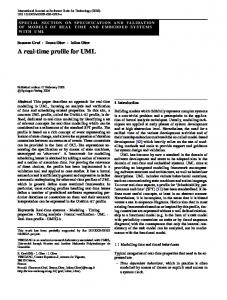
2.1. Unified Modeling Language (UML) According to the Object Management Group 2007 (OMG), modelling is the designing of software applications before coding. The only way to attain a complete picture of a system is through a model. A model can help to reveal the extent to which requirements exactly match a system. UML is an OMG standard language which is rich in graphical notations. These notations can be used by modellers to create an abstract model of their system. The latest version of UML (2.1.2, see [22][23]) supports 13 types of diagrams, which are displayed in Figure 1.
Chapter 2. Background - Unified Modeling Language (UML)
4
Figure 1
UML Diagrams Presentation in Class Diagram (UML IS)
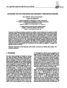
The UML specification is divided into an Infrastructure (IS) and a Superstructure (SS) documents. These two specifications provide a complete picture of UML and are briefly reviewed below in section 2.1.1 and 2.1.2. 2.1.1 UML Infrastructure The UML Infrastructure [22] is the component of the UML specification that includes all the constructs that comprise the foundation of this modelling language. The UML has a significant scope, so its constructs and modelling concepts are grouped into different language units. A language unit is a group of modelling concepts and constructs that provide users with the power to represent aspects of the system under study, according to a particular paradigm or formalism. The UML Infrastructure is architecturally aligned with the UML Superstructure. This specification is described using a metamodelling approach. The UML infrastructure is based on the InfrastructureLibrary package which makes the UML, Meta Object Facility (MOF) [21] and XML Metadata Interchange (XMI) architecturally aligned so that model interchange is fully supported [22]. The InfrastructureLibrary is used to customize the UML metamodel by profiling and creating new languages based on the same metalanguage core as UML. There are two packages in the InfrastructureLibrary (Core and Profiles). The Core package has four other packages dependant on
Chapter 2. Background - Unified Modeling Language (UML)
5
it. As shown in Figure 2, these include UML, CWM (Common Warehouse Metamodel), Profiles, and MOF.
Figure 2
Core Package And its Dependents
The Core package is subdivided into four sub-packages: PrimitiveTypes, Abstractions, Basic, and Constructs. These packages are also subdivided into further subpackages. It is however not essential to understand the entire infrastructure for this thesis. The Profiles package is neither helpful nor practical when used alone; its functionality is dependent on the Core package and it can be used in combination with either the Core package or the UML package. In the UML infrastructure, the MOF and UML packages are not categorized at the same metalevel. Metamodel and Layers
A metamodel can be instantiated into a model. These layers are relative to each other and can be used repeatedly. Figure 3, inspired by a figure in the UML infrastructure specification [22], shows a common example that uses four types of layers: •
Meta-metamodel (M3): This is the topmost level; the MOF is one example. The M3 level model has very broad scope and defines concepts that can be used to de-
Chapter 2. Background - Unified Modeling Language (UML)
6
fine all metamodels. The main characteristic of an M3 level language is that it can define itself by its own constructs and rules, in a circular way (hence, there is no need for a different M4 level). For instance, MOF can define itself. •
Metamodel (M2): This is an instance of M3, meaning that each of its constructs is an instance of an M3 level construct. M2 metamodels define the concepts and rules of a modeling language. An example of a metamodel is the UML metamodel, which is an instance of MOF. Note that concepts defined in a layer above can also be reused (or inherited) in a layer below. For instance, UML inherits part of MOF as well.
•
User-specified model (M1): This is an instance of M2. The language of M2 is used to create a model of a system at M1. An example of an M1 model is a student registration system in a university.
•
Object (M0): This is a runtime instance of M1, with concrete values for the attributes of a user-specified model. Example of M0 objects would include specific students and universities, with their names.
According to the example of Figure 3, the meta-metaclass Class is defined at the M3 level. Attribute, Class and Instance are M2 level concepts. Note that Class of M3 is from MOF, while Class of M2 is from UML. Student and University are both at M1 level (i.e. the user model) and, finally, Saeed, Martin and UOttawa are all at the M0 level, which is a runtime instance of M1.
Chapter 2. Background - Unified Modeling Language (UML)
7
Figure 3
Four Layers of Metamodel
2.1.2 UML Superstructure The UML Superstructure [23] complements the UML Infrastructure and divides the entire UML into four levels, according to an increasing level of complexity for the modelling concepts. Level 0 is simply an empty package that merges the contents of the Basic package from the UML Infrastructure (Figure 4). Level 0 has elementary concepts that allow it to function as a basic, interoperable language between various groups of modeling tools. Level 1 inherits level 0’s components and contains additional features, which include UseCases, Interactions, Structures, Actions and Activities (Figure 5). Level 2 inherits level 1’s elements, and the former’s additional features include Deployment, State
Chapter 2. Background - Unified Modeling Language (UML)
8
machine modelling and Profiles (Figure 6). Level 3 is comprised of all previous levels and contains the features that represent the complete UML, which include Modelling Information Flows, Templates and Modelling packaging (0). These levels can be used to establish a compliance level, as tools may support UML up to one of these levels only.
Figure 4
Level 0 (UML Superstructure)
Figure 5
Level 1 (UML Superstructure)
Chapter 2. Background - Unified Modeling Language (UML)
9
Figure 6
Level 2 (UML Superstructure)
The superstructure also contains the definition of the human-readable notation elements for representing the individual UML modeling concepts as well as rules for combining them into a variety of different diagram types corresponding to different aspects of models, i.e. the 13 types of UML diagrams described in Figure 1.
Chapter 2. Background - Unified Modeling Language (UML)
10
Figure 7
Level 3 (UML Superstructure)
2.2. User Requirements Notation (URN) The User Requirements Notation (URN) [3][16][27] is being standardized by the International Telecommunication Union (ITU-T) as the Z.150 series of Recommendations. URN can be defined as a graphical modelling language that is used to gather user requirements during the very early stages of design. “It enables modellers to analyze scenarios, goals and NFRs, and also to apply traceability and transformations to other languages such as Message Sequence Charts. URN was initially developed to address the elicitation, modelling, analysis, and validation of functional and non-functional requirements for new or evolving reactive and distributed systems” [3], but it is applicable to a much wider range of application domains. URN is composed of two complementary notations: the Goal-oriented Requirement Language (GRL), discussed in section 2.3 in detail, and the Use Case Map (UCM) scenario notation. Whereas GRL focuses on the “why” aspects of requirements model, Chapter 2. Background - User Requirements Notation (URN)
11
UCM target the “what” aspects. Draft Recommendation Z.151 [17] describes the details of the definitions, attributes, relationships, constraints, semantics and semantics variations of URN, GRL and UCM for both their abstract and concrete metamodels. Figure 8 gives a high-level overview of some of the top-level metaclasses of the URN metamodel. In particular, a URN specification may contain GRL and/or UCM specifications, as well as links between their elements. Links and URN model elements can also contain metadata information. urnspec 1 urnspec
URNspec name : String 1
1 urnspec
1
0..1 urnspec
urnspec
grlspec 0..1
urnLinks 0..*
0..1 ucmspec
GRLspec
UCMspec
URNlink urnLink 0..1 type : String 0..* fromLinks
0..* metadata
0..* toLinks
0..* metadata
Metadata name : String value : String
0..* metadata
0..*
fromElem 1 1 toElem URNmodelElement id : String elem name : String 0..1
Concern
GRLmodelElement
UCMmodelElement
concerns
Figure 8
High-Level Overview of the URN Metamodel (Z.151)
The rules and metalanguages used to describe the URN language in the Z.151 document are based on another ITU-T standard, namely Z.111 (Notations to Define ITU-T languages) [14]. Recommendation Z.111 standardizes notations to create abstract and concrete syntaxes of languages, using metagrammars or metamodels. “In the following a Named element is a meta-class that contains a name attribute of the meta-class Token.
Chapter 2. Background - User Requirements Notation (URN)
12
i)
Class is a Named element that contains one or more Attribute items and can participate in binary Association relations via one or both of the AssociationEnd attributes of each Association. A Class can inherit the Attribute and AssociationEnd (and hence Association) items from another Class (single inheritance only). Each Class shall have a name with a Token value that is distinct from the Token value for the name of any other Class (including predefined primitives), or any Enumeration. The inheritedFrom attribute (if present) of Class references the parent Class of a Class. An inherited Class of a Class is either the parent Class or any inherited Class of the parent Class, transitively.
ii)
Attribute is a Named element. It is a meta-class for an ordered element of a Class that has a DataType and an optional DefaultValue. The multiplicity of an Attribute is given by multiplicityMin and multiplicityMax, which have default values of 1 if they are omitted in concrete notation.
iii)
DataType is a meta-class that is either a PrimitiveType or an EnumeratedType. PrimitiveType is a DataType where the type is predefined (one of Token, Nat, Boolean, Unspecified) primitive identified by the Primitive value of the name attribute of the PrimitiveType. EnumeratedType is a DataType where the type is an Enumeration identified by name attribute.
iv)
Enumeration is a Named element that represents a (quotation) DataType whose values are represented by a set of literal elements.
v)
Literal is a Named element contained in an Enumeration that is one of the values of an Enumeration.
vi)
DefaultValue is a meta-class for the optional component of an Attribute that identifies a default value of the appropriate type.
vii) Association is a meta-class for the relation between Class meta-classes. It has
two AssociationEnd attributes (source and target) for the logical connection of the Association with the related Class meta-classes.AssociationEnd is a metaclass for the end of an Association. It has Boolean attributes that determine if the AssociationEnd is composite (isComposite), navigable (isNavigable) or
Chapter 2. Background - User Requirements Notation (URN)
13
ordered (isOrdered). If the AssociationEnd is navigable (isNavigable = true), the name shall not be empty, and the name (which corresponds to the role name of the AssociationEnd) shall be distinct from the name of any other AssociationEnd that is an end of the Class that is the source of the AssociationEnd.” [14]. Detail information is in the reference document.
The difference between Z.111 and Z.151 is that both standards exist at different metalevel layers. Z.111 uses an extended subset of Meta-Object Facility to define a simple meta-metamodel (M3) targeting the definition of modelling languages (see Figure 9), whereas Z.151 instantiates it to formalize URN’s metamodel (M2) from which userspecified goal and scenario models can be instantiated (M1) and executed with concrete values (M0). 0..* 0..1
endClass 1
Class inheritedFrom
0..*
0..*
end
Attribute
AssociationEnd
name : String multiplicityMin : Nat = 1 multiplicityMax : Nat [0..1] = 1 0..* 1
name : String [0..1] multiplicityMin : Nat = 1 multiplicityMax : Nat [0..1] = 1 isOrdered : Boolean = false isNavigable : Boolean = false isComposite : Boolean = false
0..1
Association associationLink 1
name : String 1 1 endType
attribute {ordered}
0..*
1
target 1 source 1
defaultValue 1
DefaulltValue
attributeType name
name : String
Enumeration name : String 1
DataType
Primitive Boolean Unspecified Nat String
1..*
literal {unordered}
name PrimitiveType
EnumeratedType
Literal name : String
Figure 9
Z.111 Meta-metamodel
Chapter 2. Background - User Requirements Notation (URN)
14
2.3. Goal-oriented Requirement Language (GRL) The GRL [3][17] is a language that focuses primarily on goal modelling. A subset of URN and a graphical language, GRL’s major contribution is to provide reasoning for non-functional requirements (high-level goals). GRL also works for functional requirements and has notations for both. Its focus is to design the why and the what aspects of a model. GRL integrates elements from two other goal-oriented modelling languages, i* [30] and the NFR framework [4]. The i* contains modelling elements that support goal, agent, and organization modelling, while the NFR framework provides an evaluation mechanism for goal models. GRL inherits both of these features and has become a very effective modelling language that also has the ability to evaluate any goal model. GRL divides its modelling elements into three main categories: Intentional Elements, Actor and Links Intentional Elements
Intentional elements are the constructs which are used to model the system. They carry the intentions of the stakeholders involved. There are five types of intentional elements: Softgoal, Goal, Task, Resource and Belief. Softgoals are used to model high-level goals that are uncertain or that can never be fully satisfied. They are used to describe qualities and non-functional aspects such as security, robustness, performances and usability [17]. Goals are used to describe functional requirements, which are measureable and achievable. Tasks describe how goals can be achieved, how certain actions can be performed and how softgoals can be partially satisfied. A task is an action that an actor would ideally want performed in order to determine solutions for both goals and softgoals. Resources represent physical or informational entities. A resource status is either available or not available. Beliefs are used to capture rationales and are used by modellers to understand their concepts and claims for their described goals. Actors
An actor represents a stakeholder or a system. It may contain sub-actors and intentional elements. An Actor is an entity that performs actions and makes decisions in order to accomplish goals, perform tasks and satisfy softgoals.
Chapter 2. Background - Goal-oriented Requirement Language (GRL)
15
Links
Links are used to connect intentional elements and actors to show their interrelationships. Different links have different semantics and behaviour. GRL has three types of links which are: Decomposition, Contribution and Dependency Decomposition links are used to decompose an intentional element into its subintentional elements, one or all of which should be achieved or satisfied (depending on the decomposition type) in order for the target intentional element to be satisfied. One exception is that a belief cannot be decomposed either as a source or a target. There are three types of decomposition: AND, XOR (exclusive OR) and IOR (inclusive OR). One intentional element can use only one type of decomposition at a time. Satisfaction levels can be quantitative or qualitative. Contributions are links used to describe the positive or negative impact of one or more source intentional elements to their target intentional element. Such links can be used to understand which intentional element is contributing what to another intentional element. This contribution can be quantitative (numeric value) or qualitative (one of Make, Help, SomePositive, Unknown, SomeNegative, Hurt, and Break). Correlations are similar to contributions, but they are used for modelling side effects. Dependency is another type of link indicating that an actor or intentional element depends on another actor or intentional element. All GRL notations are displayed in Figure 10.
Chapter 2. Background - Goal-oriented Requirement Language (GRL)
16
Figure 10 Summary of GRL Notations
Figure 11 is a sample model that illustrates the use of GRL constructs, including the combination of links, actor and intentional elements with different satisfaction values. This diagram is a representation of a teaching assistant (TA) candidate from a TA selection model. TA candidates expect the system to be secure and flexible. According to them, the system should allow one to apply to many courses at a time in a secure way. They do not want to enter the same information repeatedly and also do not want to submit forms by physical means at a particular office. Figure 11 shows that TA candidates can apply for positions through several means: paper-based applications or web-based applications. Web-based applications can be done securely but their availability might be limited, as not all candidates have computers.
Chapter 2. Background - Goal-oriented Requirement Language (GRL)
17
Figure 11 GRL Model Sample
GRL Strategies
GRL strategies are also a powerful feature of GRL. The process is initiated by a modeller, who assigns initial satisfaction values to some of the intentional elements (usually leaves in the GRL graph). These values then propagate in the GRL model through links, hence computing satisfaction levels for the other connected intentional elements. The strategy effect is shown by a coloring scheme applied to different intentional elements as demonstrated in Figure 12. This evaluation method is effective at an early stage of system modelling. It helps to analyze different alternatives and tradeoffs for the system and the stakeholders involved.
Chapter 2. Background - Goal-oriented Requirement Language (GRL)
18
Figure 12 GRL Strategies
2.4. Metamodel of Goal-oriented Requirement Language (GRL) A model is an abstraction of a system built with an intended purpose in mind. A model should be able to answer questions in place of the actual system [8]. A model that describes a set of related models is called a metamodel. A model is an instance of its metamodel. OMG’s MOF is a standard meta-metamodel for model-driven engineering, with standard instances such as UML and CWM. Application modellers use UML diagrams in order to create their specific models. Z.111 is GRL’s meta-metamodel, but the GRL metamodel itself is illustrated graphically with a UML class diagram. An important part of this thesis examines which classes from the UML metamodel can be extended to map to the GRL metamodel classes, without violating inherited constraints. 2.4.1 Scope The GRL metamodel provides an opportunity for all modellers (including software engineers and requirements engineers) to model requirements, especially non-functional requirements, for their proposed systems and to evaluate them by using strategies for preci-
Chapter 2. Background - Metamodel of Goal-oriented Requirement Language (GRL)
19
sion, validity and comprehensiveness. In this thesis, we focus on the GRL models elements themselves, and leave aside the notion of strategy, as the latter relates more to the evaluation of the former. 2.4.2 Overview The GRL core diagram in Figure 13 represents the GRL metamodel. It complements the URN metamodel extract shown in Figure 8. GRLspec
1 grlspec 1 grlspec
1 grlspec
includedActors 0..* 0..* actors
GRLmodelElement
Actor
0..1 includingActor 0..1 actor
links 0..*
Decomposition
linksDest ElementLink 0..*
dest 1
linksSrc 0..*
1
GRLLinkableElement
src
Dependency
DecompositionType AND XOR IOR
intElements 0..* 0..* elems
Contribution contribution : ContributionType = Unknown quantitativeContribution : Integer = 0 correlation : Boolean = false
ContributionType Make Help SomePositive Unknown SomeNegative Hurt Break
IntentionalElement type : IntentionalElementType decompositionType : DecompositionType = AND importance : ImportanceType = None importanceQuantitative : Integer = 0
IntentionalElementType Softgoal Goal Task Resource Belief
ImportanceType High Medium Low None
Figure 13 Metamodel of GRL [17]
This metamodel formalizes all the GRL concepts and constructs introduced earlier. Unlike what the name “abstract metamodel” may imply, there are no abstract classes in the abstract metamodel; there are only concrete classes. However, it is considered abstract because it does not include graphical or layout information relevant to the concrete notation. All of the constraints, semantics, attributes and notations are discussed in detail in Chapter 3. Here we only discuss how these classes interact with each other, and how such metamodel should be read. The Actor class has a self-association “includingActor” of multiplicity [0..1] and “includedActors” of multiplicity [0..*]. This association specifies that Actor may or may not contain one or more sub-Actors and all included Actors have a unique including Ac-
Chapter 2. Background - Metamodel of Goal-oriented Requirement Language (GRL)
20
tor. The Actor class has an association “elems” with IntentionalElement, with multiplicity [0..*], meaning that an Actor may or may not contain IntentionalElements. The GRLSpec contains the Actors, which are generalized by GRLLinkableElement. The IntentionalElement class has an association with the Actor class, which means that an intentional element may belong to at most one actor. The IntentionalElements are also GRLLinkableElements and are contained by GRLSpec. Note that there are various types of IntentionalElement. The ElementLink class, also contained by GRLspec class, is a generalization of Decomposition, Dependency and Contribution. The ElementLink class has two associations with GRLLinkableElement class, one describing the source and the other the target. The DecompositionType, ContributionType, IntentionalElementType and ImportanceType are enumeration classes used to capture values for the attributes of some of the classes mentioned above. GRLspec aggregates the IntentionalElements, Actors and ElementLinks (Figure 13) but is itself contained by URNspec, as shown in Figure 8.
2.5. UML Profile 2.5.1 Definition A UML profile [18] is an extension mechanism provided by UML to customize it’s metamodel. UML does not allow direct modifications of its metamodel, but the use of a UML profile enables one to reuse and extend the UML metamodel constructs with new concepts. One common interpretation of a UML profile is “the extension mechanism of a UML metamodel for a particular domain” [23]. The different constructs used to define a profile are listed below with their definitions: •
Stereotype: A construct which is similar to a class construct in UML’s metamodel. According to the UML Superstructure Profile package, stereotypes are specific metaclasses.
•
Tagged value: A construct similar to an attribute construct of a class in UML’s metamodel. According to the UML Superstructure Profile package, tagged values are standard meta-attributes.
Chapter 2. Background - UML Profile
21
•
Constraints: Restrictions required in a particular domain.
2.5.2 The Purpose of UML Profiles The purpose of introducing UML profiles is to give modellers the means to customize the UML metamodel without directly changing it. Modellers can utilize stereotypes, tag values and constraints for this customization. However, some restrictions still apply, as the modeller can introduce new constraints, but cannot violate any inherited constraint from the original UML metamodel. Being able to customize the UML metamodel through a UML profile is an effective method to improve and narrow the scope of the original UML metamodel for a specific domain. In many cases, like in the finance or manufacturing domains, there is no need to create profiles because the original UML constructs already fulfill modelling requirements. The profile’s most prominent use is when a new, domain-specific language is being introduced. In order for a community to define and integrate a new language, a profile can be created to extend the UML metamodel. There already exist multiple standard UML profiles available on the OMG Web site [20], including: Systems Modeling Language (SysML); Common Object Request Broker Architecture (CORBA); Enterprise Application Integration (EAI); Enterprise Distributed Object Computing (EDOC); Profile for Modeling and Analysis of Real-time and Embedded System (MARTE); Schedulability, Performance and Time; Software Radio; Voice; and Testing. 2.5.3 UML Profile Creation There are different ways of creating a UML profile. These different ways are [18]: Stereotype Mechanism (SM)
This is a very common and straightforward method of creating a UML profile. The stereotype mechanism is an extension of the basic UML elements and is supported by most UML tools. This method is comprised of several steps: •
Assigning a new name to an extended metaclass, which will be represented as a stereotype of UML;
Chapter 2. Background - UML Profile
22
•
Adding new attributes in the stereotype, which are called tags;
•
Adding new constraints to the stereotype. However, we cannot weaken existing UML metamodel constraints;
•
Assigning a new appearance to the stereotype. Some limitations still exist for this method, including that the modeller may pol-
lute the diagram by mixing domain-specific diagram constructs with predefined UML diagram constructs, hence possibly hurting the understandability of models. Metamodel Extension Mechanism (MEM)
This mechanism [29], which includes the functionalities of SM, is a less common method of creating a UML profile. It allows the extension of non-basic UML elements and imposes restrictions that allows for the sole use of domain-specific assigned diagrams to stereotypes. While it is more flexible, the MEM is a more complex approach of profiling and is supported by fewer tools than the SM. 2.5.4 Profiling Related Tools There are a number of tools which provide support for creating UML profiles. Table 1 lists popular commercial UML tools. Table 1
Tools supporting UML Profiles
Company Name
Tool Name
@-portunity
Blueprint SM
ARTiSAN software
ARTiSAN Studio
IBM
Rational Software Architecture (RSA)
Telelogic (IBM)
Tau G2
MID
Innovator
No Magic
MagicDraw
MDWorkbench-Sodius MDWorkbench Objecteering software
Objecteering 6.1
There exist other tools and technologies for domain specific modelling (DSM) that are not based on UML. These include the Generic Modelling Environment (GME)
Chapter 2. Background - UML Profile
23
[11], Xactium’s XMF-Mosaic [28], and the Eclipse Modeling Framework (EMF) [7]. There has been previous research which has used a number of factors to analyze which tool is more suitable for prototyping an editor for an evolving graphical language, and a subset of GRL was used as an example [2]. “These evaluation factors are Graphical completeness (Can we represent all the notation elements?), Editor usability (Does the editor generated support undo/redo, load/save, simple manipulation of notation elements and properties, etc?), Effort (How much time and effort is required to learn the approach and produce DSML tools?), Language evolution (How are older models handled when the language or metamodel evolves?), Integration with other languages (How can we support additional languages(e.g., Use Case Maps in combination with GRL) or integrate with other tools?), Analysis capabilities (Can we easily analyze or transform models produces with the graphical editor?)”[2]. UML profiling tools were also part of this study. One of the conclusions was that Telelogic Tau G2 was superior to IBM’s RSA [10] in terms of support for UML profiles in that context. In particular, Tau G2 supports both the stereotype mechanism and the metamodel extension mechanism discussed earlier, whereas RSA only supports the former.
2.6. ITU-T Support for Profiles There is an ITU-T standard document, Recommendation Z.119 [15], which provides guidelines for creating a UML profile for a modelling language. According to these guidelines, a profile can be expressed by the following headings and descriptions: •
Scope: The span of the profile, which states the rules for conformance, as well as the notation guidelines for UML.
•
References: A valid source that provides information about a specific topic. Examples include the relevant ITU-T system design languages, the UML SS, the Object Constraint Language, and if applicable, MOF.
•
Definitions: The terms and explanations provided in the standard.
•
Abbreviations and acronyms.
•
Conventions: Includes name resolution, the drawing style, and formal notations for mapping, translation and transformation.
Chapter 2. Background - ITU-T Support for Profiles
24
The main text of the profile is also the subject of many guidelines: •
Defining the profile o Stereotype summary: Ideally comprised of a UML diagram that provides the stereotype definitions and explanations of which class of the UML metamodel maps with which class of a particular language metamodel (like in our case, the GRL metamodel), the stereotype summary can also be presented in a table. o Stereotypes o UML Metamodel: This should be an appendix to the profile document that summarizes the relevant parts of the UML metamodel. This is not strictly necessary, but may make the profile document easier to understand.
•
Structure of stereotype sub-clauses o Attributes: the stereotype characteristics that the modellers select from the extended UML metaclass and any new required characteristics. Modellers can set default or initial values, as well as data types. o Constraints: the rules that are passed down from the extended metaclass. Modellers are also allowed to apply new rules as required. o Semantics: The mapping between the UML metaclass and the stereotype, as well as the corresponding ITU-T language element. Items for consideration include the new class concept in the new model, as well as its original meaning in the UML metamodel. o Notations: The creation of new representations if there is any change from the inheriting class. o References: It specifies where to find related sections of the UML SS and ITU-T Recommendation(s). While strictly this is not needed, it will be invaluable for readers so that the relevant parts of UML SS and ITU-T Recommendation(s) can be found and the effect of the profile understood.
One of the profiles standardized by ITU-T is the Z.109 UML profile for SDL (Specification Description Language) [13]. GRL is very different from SDL. While SDL [12] is a language used for specifications and behaviour descriptions of telecommunica-
Chapter 2. Background - ITU-T Support for Profiles
25
tion systems, GRL deals with modelling and evaluating goals and requirements. As the SDL profile mostly extends the UML metaclasses without conceptually altering them, there remains a need to discuss the semantics, value and constraints of every single attribute that the metaclass possesses or inherits from its parent classes.
2.7. Related Work on Goal Modelling Profiles 2.7.1 Requirements for a Profile for Goal-oriented Modelling Goal-oriented profiles shall support different functionalities and satisfy the quality criteria expressed by the following four requirements: R1. Integration with UML: This is the ability of sharing information between the goal-oriented modelling diagram and the existing UML diagrams. It is apparent that UML diagrams share some information and knowledge with each other. For example, an instance of a class from a class diagram can be used as a lifeline in a sequence diagram. Hence, in this specific case, there must be an evaluation of how the GRL diagram integrates with other UML diagrams. R2. Diagram Pollution Avoidance: Different diagrams offer different viewpoints on the same model. In most UML tools, whenever a UML diagram is created, a separate editor for each diagram type, with a customized toolbar, is used in order to maintain the diagram “purity”. The allocation of unique toolbars and editors for each diagram prevents the “pollution” or mixing of different diagram constructs. In order for modellers to use GRL diagrams, based on GRL profile, without polluting other diagrams, and vice-versa, it is important that the profile promotes this feature. R3. Metamodel Stability: A metamodel is considered stable if it is standardized or if it has reached a good level of maturity through tool support and a community of users. The stability of the underlying metamodel is very important for the evaluation of any goal-oriented modelling profile. R4. Implementability of the Profiling Mechanism: The profiling mechanism used must ease the implementation and proper tool support of the profile. This
Chapter 2. Background - Related Work on Goal Modelling Profiles
26
is important as some profiles are expressed in vague terms or in ways that are incompatible with UML tools. These requirements will be used to evaluate the work of others and later, in Section 5.3, to evaluate our own work. 2.7.2 Evaluation of Related Work In this section, we will analyze four research works [5][6][9][25] close to our work. Evaluation and analysis of these works are based on their level of satisfaction to our stipulated requirements. Research Work 1: A Template-based Analysis of GRL
A template-based analysis of GRL has been conducted by Dallons et al. in [6]. However, there is no actual profile for goal modelling in this work. The authors considered three concrete syntaxes for GRL: 1) a textual syntax (expressed in Backus-Naur Form (BNF), 2) a graphical syntax (also expressed in BNF, but augmented with topological information) and 3) an Extensible Markup Language (XML) syntax (expressed as an XML Document Type Definition (DTD)). Other considerations include informal semantic definitions of constructs, examples of GRL models and a tutorial. A conclusion reached by [6] is that a GRL metamodel should be comprised of four different concepts shown in Figure 14 Figure 17. These are: Actor, IntentionalElement, NonIntentionalElements and IntentionalRelationship.
Chapter 2. Background - Related Work on Goal Modelling Profiles
27
Figure 14 Top Level View of GRL Metamodel [6]
Chapter 2. Background - Related Work on Goal Modelling Profiles
28
Figure 15 GRL Metamodel: Zoom on Intentional Elements [6]
Figure 16 Types of Intentional Relationships [6]
Chapter 2. Background - Related Work on Goal Modelling Profiles
29
Figure 17 GRL Metamodel: Zoom on Intentional Relationships [6]
The authors of [6] applied an already established template-based analysis on their metamodel. “The template was proposed by Opdahl and Hendeson Sellers as a means to sys-
Chapter 2. Background - Related Work on Goal Modelling Profiles
30
tematize the description of Enterprise Modelling Language (EML) constructs. It can be used for various purposes like comparing and integrating EML constructs or, simply, for better understanding them. Translating models from one EML to another is another possible use. In Version 1.1 of the template, each construct is defined by filling in the following sections: Preamble (General issues are specified here, i.e., constructs, diagram type, language name and version, acronyms and external resources.), Presentation (such issues are lexical information (icons, line styles), syntax and layout conventions are specified here.), Semantics (It requires the analyst to answer some questions which are in detail discussed in [6]), Open issues (All the issues that the template failed to address should be mentioned here.)” [6] The assessment concluded that the GRL specification is very vague and the scope of the definitions is very broad. They noted confusion with the definition and semantics of Actor. They raised a number of questions including whether there should be subtypes of Actor, the difference between roles and actors, as well as issues concerning whether tasks and goals could be decomposed. Additionally, they provided suggestions to improve the GRL textual syntax. Their research does not demonstrate any integration with the existing UML diagrams. The research was based on a metamodel that was not valid or stable. It can be considered more as a theoretical effort as there is no mention of a practical implementation of the profile in any tool. In the evaluation part below, we give an analysis of how the work in [6] satisfies our requirements. Evaluation
R1. Integration with UML: It can be concluded that this work does not fulfill requirement R1 since the research does not demonstrate any integration with the existing UML diagrams. R2. Diagram Pollution Avoidance: This requirement is not satisfied because of the lack of a practical implementation. R3. Metamodel Stability: The metamodel does not satisfy the requirement for stability. As mentioned in [6], a GRL metamodel did not exist at the time of the work. So the proposed metamodel is a supposed metamodel with no guarantee of validity.
Chapter 2. Background - Related Work on Goal Modelling Profiles
31
R4. Implementability of the Profiling Mechanism: This requirement is not satisfied because the constructs were only verbally mapped. In order for this requirement to be satisfied, one needs to implement the profile through the use of profile supporting UML tools after mapping it. Research Work 2: UML Profile for Enterprise Goal Modelling
Figure 18 shows a UML profile proposed by Grangel et al. [9] for enterprise goal modelling at the Computation Independent Model (CIM) level. “It is used to represent domain and system requirements. It is based on business models and shows the enterprise from a holistic point of view that is independent of the computation” [9]. The concepts are divided in two parts: CIM-Knowledge and CIM-Business. The top-level general vision of the enterprise and its knowledge are discussed in the first part. The second part involves details of the enterprise knowledge, through the examination of its business representation. The depiction adheres to organisational, structural and behavioural models.
Figure 18 Proposal for Enterprise Knowledge Modelling [9]
The work in [9] is based on the Unified Enterprise Modeling Language (UEML), and the Process, Organisation, Product, and so on (POP*2). They proposed a metamodel for goal modelling shown in Figure 19:
2
In POP*, * means so on
Chapter 2. Background - Related Work on Goal Modelling Profiles
32
Figure 19 Goal Metamodel: Organizational Metamodel Excerpt [9]
The metamodel distinguishes four different conceptual constructs: “Objective (this represents any target that enterprises want to achieve, it is possible to define it at different hierarchical levels, such as strategic, tactical and operative levels. At the strategic level, this construct is also used to represent the enterprise’s mission and vision.), Strategy (this represents how the enterprise wants to achieve the objectives proposed at the strategic level), Plan (this represents the organisation of the work at different hierarchal levels in order to accomplish the objectives and strategy defined in the enterprise) and Variable (this represents any factor that is able to influence the execution of the plans defined in the organisation)” [9]. The profile has been implemented in IBM Rational Software Modeler Development Platform and in MagicDraw UML 12.0. Figure 20 shows stereotypes created for the implementation of the profile. Below is an evaluation of this work from our perspective.
Chapter 2. Background - Related Work on Goal Modelling Profiles
33
Figure 20 Diagram of the UML Profile for Enterprise Goal Modelling [9] Evaluation
R1. Integration with UML: This requirement can be satisfied by [9]. It is supported by most tools to reuse the constructs of UML diagrams. It is apparent that they created stereotypes, so they can be reused in other UML diagrams. R2. Diagram Pollution Avoidance: The implementation is based on SM, which does not allow for the creation of a separate editor. The modellers are therefore forced to use a different diagram editor (most likely a Class diagram editor) that allows for their metamodel constructs to become polluted through the mixing with other UML diagram constructs (e.g. with Class diagram constructs). R3. Metamodel Stability: We cannot assert that the metamodel fulfills all aspects of Goal-oriented Modelling, since there is no pre-existing editor based on their proposed metamodel. Their metamodel is neither a standard nor in an ongoing process of standardization. R4. Implementability of the Profiling Mechanism: This requirement is partially satisfied, as the profile is implemented in the IBM Rational Software Modeller Development Platform and MagicDraw UML 12.0 through the use of Stereo-
Chapter 2. Background - Related Work on Goal Modelling Profiles
34
type Mechanism (whereas Metamodel Extension Mechanism is the recommended approach for profiling [18][29] ). Our claim of partial satisfaction of this requirement by their work is motivated by the use of the simple stereotype mechanism for implementation. As mentioned in [18][29], the metamodel extension mechanism is recommended. Research Work 3: UML Profile for Softgoal by Use Case Driven Approach
Supakkul and Chung [25] proposed a metamodel for NFR concepts, and its integration with the UML metamodel through the use of the UML profile extension mechanism. The integration of UML and NFR notations occurs in a Use Case diagram. NFRs are represented as softgoals and associated with appropriate Use Case model elements as depicted in Figure 21.
Figure 21 NFR Association Points in UseCase Model for NFR Types [25]
The profile is also referred to as Softgoal Profile because NFRs are considered as softgoals. It consists in two parts: •
Softgoal Interdependency Graph (SIG) subprofile: A representation of the concepts used in the NFR framework.”The NFR Framework is a goal-oriented approach for addressing NFRs. In this framework, they represent NFRs as NFR softgoals to be satisficed.”[25]
Chapter 2. Background - Related Work on Goal Modelling Profiles
35
•
Procedure subprofile: A representation of the concepts that are related to the method, correlation rule and evaluation procedures. The Procedure subprofile may import the SIG subprofile for use in its stereotypes.
The modeller can use these profile stereotypes with the combination of UML standard notations. The authors implemented their work and used the London ambulance dispatch system as a case study. Evaluation
R1. Integration with UML: The authors of [25] did not mention which mechanism was considered for their profile implementation. From their diagrams and references, it appears that they used SM. As a result, they fulfill our stipulated requirement. R2. Diagram Pollution Avoidance: The constructs can be polluted by the UML diagram constructs. The authors mention that their profile allows users to model using a combination of UML standard notations and their stereotypes. R3. Metamodel Stability: The metamodel is only partially stable, as it is inspired from the NFR framework which does not fully address the goal-modelling domain. Furthermore, there is no editor solely based on the metamodel. R4. Implementability of the Profiling Mechanism: We are not able to assess the work based on this criterion. It is not clear from [25] which tool the authors used for the implementation of their work, or whether it is purely a theoretical concept. Research Work 4: Using UML to Reflect Non-Functional Requirements
Cysneiros et al. [5] based their study on the idea that there should be an integration of NFRs with functional requirements. They remarked that there are two cycles to the software development process: one which covers functional requirements and the second, which comprises non-functional requirements. There is no integration of these two cycles. They concluded that there is a requirement for a junction point that would integrate these two independent cycles. Figure 22 shows their proposed strategy for integration.
Chapter 2. Background - Related Work on Goal Modelling Profiles
36
Figure 22 An Strategy Overview for Dealing with NFR [5]
In this strategy, the integration point is called Language Extended Lexicon (LEL). Functional and non functional views are joined at that point. The junction point is used to register the words or phrases unique to a specific field of the application. A LEL can hold information from both functional and non functional requirements. “To build the NFR model one must search all entries of the LEL looking for notions that express the need for an NFR. For each NFR found, create an NFR graph expressing all the operationalizations that are necessary to satisfice this NFR. It resulted, at end, a set of NFR graphs that represent the non functional aspects of the system”[5]. Cysneiros et al. claim that their proposed solution covers all diagrams. For instance, Figure 23 shows how NFR graphs are integrated with Class diagrams. The term integration means in this context that “every root of each NFR graph must refer to an LEL symbol and every class of the Class diagram must be named using an LEL symbol” [5]. Cysneiros et al. also proposed some heuristics for the convergence process. •
They created a stereotype for classes which are used to satisfy a NFR.
•
They represented a link to the non-functional view beside each operation that has been included to satisfy an NFR.
Chapter 2. Background - Related Work on Goal Modelling Profiles
37
•
Each operation may have pre- and post conditions.
•
An attribute can be added to satisfy a NFR and it may use the same expression as in the operations to create a link to the non-functional view.
The approach has been validated through case studies.
Figure 23 The Class Diagram Integration Process [5] Evaluation
R1. Integration with UML: This work does not meet the integration criteria. R2. Diagram Pollution Avoidance: This work cannot be evaluated according to this requirement because the proposed strategy differs from UML profiling. They did not create any stereotype. R3. Metamodel Stability: For the same reason as above, the work cannot be evaluated according to this requirement. R4. Implementability of the Profiling Mechanism: For the same reason as above, the work cannot be evaluated according to this requirement.
Chapter 2. Background - Related Work on Goal Modelling Profiles
38
Overall Analysis of Previous Work
Table 2 gives the overall view of previously discussed research works and their satisfaction level with our stipulated requirements. It is observed that none of the discussed approaches satisfies all four requirements. Some requirements are not applicable (N/A) with their work (and we suspect they are not satisfied) and some are partially satisfied.
Table 2
Overview of Previous Work Contributions Integration
Diagram
Metamodel
Tool
with UML
Pollution
Stability
Support
Avoidance A Template based analysis of GRL
Not Satisfied
Not Satisfied
Not Satisfied
Not Satisfied
Satisfied
Not Satisfied
Not Satisfied
Partially Satisfied
Satisfied
Not Satisfied
Partially Satisfied
N/A
Not Satisfied
N/A
N/A
N/A
UML profile for Enterprise Goal Modelling UML profile for Softgoal by use case driven approach Using UML to reflect nonfunctional requirements
2.8. Chapter Summary In this chapter, we provided a review of the UML architecture, examined the different levels of metamodelling, discussed URN in detail and reviewed some related work on goal-oriented modelling profiles. The UML architecture is divided into two parts known as UML infrastructure and UML superstructure. The different levels of metamodel are referred to as M3, M2, M1 and M0. The MOF is at the meta-metamodel level (M3), the UML at the metamodel level (M2), user-specified models are at level M1, and objects at level M0. The URN includes the UCM notation and GRL. The former is used for modelling scenarios and functional requirements, while GRL exists specifically for modelling goals and non-functional requirements. GRL’s main elements include Intentional elements, Actors and Element Chapter 2. Background - Chapter Summary
39
links. We also discussed the GRL metamodel and presented GRL strategies used for model evaluation. Profiling was discussed as a UML feature that is used to customize the UML metamodel because modellers are prevented from directly customizing the UML metamodel. There are two approaches for creating a profile: a Stereotype Mechanism and a Metamodel Extension Mechanism. The ITU-T has published a Recommendation on the creation of UML profiles for modelling languages. We gave a brief analysis of four goal modelling and profiling approaches related to our work and compared them against four requirements. While there have been some interesting contributions, existing approaches do not fulfill our established criteria for a goal-oriented modelling profile.
Chapter 2. Background - Chapter Summary
40
Chapter 3.
UML Profile for GRL
In chapter two, we discussed prerequisites for writing a GRL profile in detail. The current chapter embodies the core work of this thesis, including how we map the UML metamodel to the original GRL metamodel. In section 3.1, we discuss naming conventions which are used in this profile. Section 3.2 provides a summary of the GRL metaclasses and their extensions from the UML metaclasses in tabular form. In section 3.3, we separately map each GRL metaclass with a UML metaclass. We also discuss GRL metaclasses semantics, attributes, constraints and notations. Section 3.4 then provides a global overview of the GRL profile. GRL model elements have an id attribute that is unique inside the model and that does not change as new versions of the model are created. It is used to enable traceability from between versions of a GRL model and between a GRL model and external requirements or other types of models. GRL model elements also have names but these names can be modified from one version to the next, and their uniqueness has a scope that is smaller than the model (e.g., actor names are all different, but the name of an actor can be the same as the name of an intentional element).
3.1. Conventions, Names and Template 3.1.1 Conventions This work uses the conventions defined in ITU-T Rec. Z.119 [15]. These conventions are repeated below: •
A term in this profile is a sequence of characters making up either an English word or a concatenation of English words. The sequence of characters indicates the meaning of the term.
•
An underlined term refers to a UML term or a term defined by a stereotype in this profile. A term beginning with a capital letter denotes a metaclass.
Chapter 3. UML Profile for GRL - Conventions, Names and Template
41
•
A term preceded by the word "stereotype" designates a UML stereotype according to the stereotype concept defined in the UML Superstructure specification documentation (usually in a phrase “The stereotype X extends the metaclass X” where X is a term). The stereotype is required when its multiplicity is [1..1] (that is the derived attribute isRequired of the Extension association between the extended metaclass and the stereotype is true). If the multiplicity of the stereotype is [0..1], the stereotype is not required.
•
The convention for a term enclosed in > is extended to allow GRL qualifiers to be used. The convention for a term enclosed in < and > is extended to allow GRL concrete syntax to be used. A convention on the meaning of terms in italics is added. o A term enclosed in > refers to a stereotype described by this profile. These terms are not underlined. o A term in italic in a stereotype description refers to a GRL abstract syntax item. o A metaclass enclosed in > and preceded by “GRL” is a GRL metamodel class and is not underlined. Here the term in is the name of a GRL metaclass.
•
All owned attributes of stereotypes are in the attribute section and all inherited attributes are in the semantics section.
In addition, the prefix “/” is often used to indicate a UML association role (e.g., /superClass).
3.2. Stereotype Summary The following table lists the stereotypes with the UML metaclass that each stereotype extends. A description of the stereotypes is provided in section 3.3.
Chapter 3. UML Profile for GRL - Stereotype Summary
42
Table 3
Stereotype, Metaclass Mapping Information
Stereotype
Stereotyped UML metaclass
GRLspec
Model
GRLmodelElement
NamedElement
GRLLinkableElement
Class
Actor
Class
IntentionalElement
Class
IntentionalElementType Enumeration ImportanceType
Enumeration
ElementLink
Relationship
Contribution
Association
ContributionType
Enumeration
Dependency
Association
Decomposition
Association
DecompositionType
Enumeration
3.3. Structure of the Goal-oriented Requirement Language (GRL) Profile 3.3.1 GRLspec The stereotype GRLspec is mapped from the metaclass Model with multiplicity [0..1]. Note: The stereotype GRLspec is intended to work as a container for GRL specifications. Attributes
No attributes. Constraints
No constraints. Semantics
None. It is a structural concept. Notation
There is no notation for Model.
Chapter 3. UML Profile for GRL - Structure of the Goal-oriented Requirement Language (GRL) Profile 43
References
•
UML SS:
17.3.1 Model (from Models).
3.3.2 GRLmodelElement The stereotype GRLmodelElement extends the metaclass NamedElement with multiplicity [0..1]. Note: This stereotype contains GRL concept metadata to associate with other model elements. Attributes
Stereotype attributes: •
id: String
Defines the identifier of the NamedElement.
Constraints
•
NamedElement has a unique id tag within the URN specification.
•
Each NamedElement must have a unique name.
Semantics
Attribute name: String of NamedElement is mapped with the name of NamedElement. Notation
There is no notation for NamedElement. References
•
UML SS: 7.3.33 NamedElement (from Kernel, Dependencies).
3.3.3 GRLLinkableElement The stereotype GRLLinkableElement extends the metaclass Class with multiplicity [0..1] Note: The stereotype GRLLinkableElement is intended for generalizing GRL and GRL .
Chapter 3. UML Profile for GRL - Structure of the Goal-oriented Requirement Language (GRL) Profile 44
Attributes
Stereotype attributes: •
Defines the identifier of the Class.
id: String
Constraints
•
Class has an id tag that must be unique within the URN specification.
•
Each Class must have a unique name.
Semantics
The attribute name:String of Class is mapped with the attribute name of NamedElement. Class contain common properties with both GRL and GRL. Notation
There is no notation for Class. References
•
UML SS:
•
UML SS: 7.3.33 NamedElement (from Kernel, Dependencies)
7.3.7 Class (from Kernel)
3.3.4 Actor The stereotype Actor extends the metaclass Class with multiplicity [0..1]. Note: In this profile, Class behaves as a new GRL concept. Here, GRL behaves as a container and stakeholder. A GRL can depend on other actors and intentional elements and can also contain other actors and intentional elements. Attributes
Stereotype attributes: •
id: String
Defines the identifier of the Class.
Chapter 3. UML Profile for GRL - Structure of the Goal-oriented Requirement Language (GRL) Profile 45
Constraints
•
An Class cannot include itself, either directly or indirectly.
•
An Class has an id tag that must be unique within the URN specification.
•
Each