A UML Profile and a FUJABA PlugIn for modelling dynamic software architectures Mohamed Nadhmi MILADI University of Sfax ReDCAD Laboratory Route Soukra Km 3.5 B.P W 3038 Sfax Email:
[email protected]
Mohamed JMAIEL University of Sfax ReDCAD Laboratory Route Soukra Km 3.5 B.P W 3038 Sfax Email: mohamed.Jmaiel@ enis.rnu.tn
Abstract In this paper we propose an UML profile and a FUJABA Tool Suite PlugIn for modelling components based on dynamic software architecture. This former called “Architectural PlugIn” implementing a new UML Profile [10] and allowing the mapping built models to XML language after validating the obtained generated files with respect to its schemas. In fact, the UML profile enables us to model dynamic software architectures which is in turn made up of three diagram types: the first type deals with the structural aspect defining the architectural style of an application, the second handles the dynamic aspect by modelling a set of reconfiguration operations and the final one that models the coordination among the reconfiguration operations defined in the above aspect.
1 Introduction Nowadays, software has an important role in various systems among of which the critical infrastructures or transportation systems. These systems should have special proprieties such as availability and reliability that have to be satisfied by the software parts [18]. More piece of evidence, these mentioned systems are found in numerous fields for example : telephone switching systems, banking systems, mobile embedded systems . . . More deeply, unmanned control systems and critical systems such as spacecraft navigational systems need robustness to detect and to repair automatically anomalies at run-time [17]. Dynamic reconfiguration techniques appear to be a promise for building systems that have requirements for adaptability and/or high availability. In fact, it is the process of making changes to an executing system without requir-
Mohamed hadj Kacem University of Sfax ReDCAD Laboratory Route Soukra Km 3.5 B.P W 3038 Sfax Email: mohamed.hadjkacem@ fsegs.rnu.tn
ing the temporary system shutdown [5]. In order to provide a more generic and systematic independent view, we need to describe the software architecture and the dynamic reconfiguration at a high-level of abstraction. Languages which deal with software architectures can be divided into three classes. The first corresponds to Architecture Description Languages (ADL), like Darwin [3], Olan [1], and Rapide [14]. However, most of ADLs describe architecture evolution by the use of some predefined configurations that can’t draft all architectural changes [9]. The second includes works that are based on formal techniques such as graph based techniques [6, 16, 20], logic based [4] and algebra process based [19]. Whereas, these techniques are generally difficult to apprehend. The third one corresponds to the Unified Modelling language (UML) [15] which became a standard as well in the industrial community as the academic one. Despite the founded innovations in the 2.0 version, this language remains inappropriate in modelling dynamic architectures [10]. In a sense, UML gives all necessary elements to model component based software architecture. The modelling of such architecture was almost achieved by important innovation in the component diagram (new component notation, port, required interface and provided interface notation) and the composite structure diagram (one of the four new diagrams introduced in UML2.0) [15]. All these innovations focus on the modelling of static software aspects. Nevertheless, the dynamic aspect of such architectures in terms of reconfiguration and architectural evolution, didn’t specifically deal in UML language. In order to cover these weaknesses, we propose a new UML profile called “architectural profile” [10] which combines the expressive UML powers and graph grammar. It allows to model software architectures (structural, dynamic and coordination aspects). To be more precise, the structural
aspects are graphically modelized using the component diagram. Moreover, in terms of configuration operations which are based on graph rewriting rules, the dynamic aspect is defined. In addition, the coordination protocol is defined as a partial order among reconfiguration operations. In this paper we focus on a FUJABA PlugIn that implements the proposed UML profile. The Developed “architectural PlugIn” did not allow us to model such architectures but also to map the resulted models towards the XML language. Baring in mind, all constructed models are validated through XML schemas (integrated in the PlugIn). Furthermore, the architectural PlugIn has been developed by the use of a set of rules that enables it to ensure the integrity of each model as well as the coherence between different models. The rest of the paper is organized as follows. Section 2 presents the software architecture modelling. Section 3 describes the modules of our “architectural PlugIn”. In section 4 we will present a Patient Monitoring System case study to more illustrate our new approach. Section 5 will concludes the whole work with some suggested future works.
« ReconfOperationName »
expressed
« OCL »
« StructuralName »
« ReconfigurationOperation » « Guards »
« StructuralProfile »
« Require & Delete » « Insert »
« DynamicFeature »
« StructuralFeature »
« Require & Preserve » « Architecture » 1..*
2..*
Connector
Component 0..*
ha s
1..*
ConnectorKind
Port +/provided 0..*
+/required 0..*
enumeration Assembly
Interface
Delegation
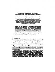
Figure 1. Architectural profile the dynamic aspect that models the architecture evolution through some reconfiguration operations and the coordination aspect that depicts coordination within these operations.
2 Architecture modelling
• Modelling structural aspect is realized by three different parts described in figure 2. Firstly, the top part, known as the “structural name” stereotype that defines the architectural style name. Secondly, the central part, identified by “structural feature” stereotype that models the architecture component and connections types. Finally, the bottom part, which is identified by “guards” stereotype, models a set of architectural properties that should to be verified for all possible configurations belonging to the style. All the architectural properties are expressed in the OCL language [12, 13].
UML has been based on a four-level meta-modelling hierarchy since its first version. Each level (except the top) is presented as an “instance of” its former. More specifically, UML defines models which can be used in different ways during the project development and proposes metamodels which define the mentioned models language expression. Because of these shortcomings in UML language (especially in model dynamic component software architecture [10]), we developed an “architectural profile” that uses UML extension techniques. Thus, modelling dynamic component software architecture is built on two levels :
2.1
« Constraint »
Architectural_style
Meta-Model Level
The architectural profile is built upon the UML metamodel and more precisely the component diagram metamodel. In fact, the meta-model of the new profile [8] as depicted in figure 1 preserves the meta-classes of the component diagram meta-model (we represent in white color just meta-model component diagram elements on which the extension will take place) and extends through meta-classes addition (represented in gray color) that describes the profile.
2.2
Figure 2. Architectural style aspect
Model level • Modelling dynamic aspect means giving elements in order to specify the architecture structural evolution in terms of adding / or deleting components and connections. Thus, modelling dynamic aspect is made to
The model level of the “Architectural Profile” specifies software applications component due to three basic aspects: the structural aspect defines the structural architectural part, 2
3.1
allow application evolution from one configuration to another. In fact, the description of a reconfiguration operation is composed mainly of three different parts described in figure 3. The top part identified by “Reconfiguration Operation” stereotype names the reconfiguration operation. The central part, in its turn, is made up of three parts. On the left we find a part identified by “require & delete” stereotype that models the components and/or connections which will be deleted during the operation. In the middle, we find a part identified by “require & preserve” stereotype that models the components and/or connections intervening in the operation without being changed. On the right, we find a part identified by “insert” stereotype that models the components and/or connections which will be inserted during the operation. Finally, the bottom part identified by “guards” stereotype specifies the constraints that must be imperatively respected before its execution. As we know, all constraints are expressed by OCL language.
In using this module, “Architectural Plugin” users model dynamic application through the structural, dynamic and coordination aspects. However, an “Architectural Plugin” users are not essentially experts in the dynamic software architectures modelling. So, they can make various errors such as syntactic errors or graphical modelling errors. . . That’s why, the “Architectural Plugin” development was made by a set of rules assuring the coherence and the validity of the three aspects. In their turn, these rules can be classified into two main categories. The first, called “inter-model rules” that permits model’s validation within the same aspect. The second, called “intra-model rules”, manages coherence among the three aspects. 3.1.1 Inter-model Rules These rules check the model validity of each aspect alone ( structural, dynamic and coordination). The implementation of each one respects some rules. In fact, there are some common rules within the aspects on one hand. On the other hand, there are other specific to each aspect.
Architectural_style
Graphic Module
• The structural aspect as depicted in figure 2 is dedicated to model the dynamic application structure due to some rules. In fact, there is only one structural diagram in the application modelling. It models the application architectural styles. Thus, the structural diagram is composed of two parts : “structural feature” and “guards” are identified with a unique structural name. The structural feature part includes architectural elements (components, ports, required interfaces, provided interfaces, assembly connections, delegation connections and sub-components). It models only components type (don’t model component instances).The structural aspects must be available during the application modelling.
Figure 3. The dynamic aspect • The coordination aspect models the dependency among the reconfiguration operations specified in the dynamic part. Thus, it represents how these operations must be managed in order to ensure the application evolution. This aspect is based on activity diagram which differs from this latter that is to say each activity models a reconfiguration operation defined in the previous aspect.
• Dynamic aspect as depicted in figure 3 is dedicated to model reconfiguration operations and respects some rules. In fact, modelling dynamic aspect includes at least one reconfiguration operation diagram (generally includes many reconfiguration operation diagram). A reconfiguration operation diagram is identified by its name. Moreover, it is composed of four major parts (“require & delete” , “require & preserve”, “insert” and “guards”). The first three parts model the inserted, deleted or preserved component’s type during operation reconfiguration execution. Furthermore, its name is represented by the following format : component’s instance name : component’s instance type. Finally, guard’s part model some constraints to be verified before reconfiguration operation execution. Thus, the
3 Architectural Plugin: basic modules Architectural Plugin is built essentially on two basic modules. The first, allows us to draw various UML models as it is mentioned in the previous section(meta-model level). Thus, any plugin user can model dynamic applications basing on theses three former aspects. The second allows the mapping of these models towards XML language and the validation of the generated file with XML schemas. 3
new system architecture always preserve the architectural style’s constraints.
one of the defined connection in the structural feature within the same interfaces.
• Coordination Aspect is dedicated to model the coordination within the reconfiguration operations with respect to some rules. In fact, a reconfiguration operations diagram includes reconfiguration operation nodes and all standard model elements of an UML activity diagram such as initial, final, decision, merge, fork or join nodes . . . A reconfiguration operation diagram must begin with a unique initial node and have to be finished with one final node at least. Coordination diagram model the coordination between reconfigurations operation. Thus, differently to UML activity diagram, each activity models one of the reconfiguration operation detailed in the previous aspect (reconfiguration operation node stereotype). Finally, the deletion of a reconfiguration operation node or a reconfiguration control node implies the deletion of all related links.
• Dynamics towards coordination : A coordination diagram can be created only if there is is an already dynamic diagram creation. Each reconfiguration operation node in the coordination diagram corresponds to a reconfiguration operation diagram in the dynamic aspect.
3.2
XML Module
This module enables us to transform “Architectural Plugin” models from graphical format towards a textual one with respects to XML language. The XML generation files covers the three mentioned aspects. Each file can be validated by its schema. This latter validation was precisely realized by the use of XERCES API through Apache XML Project [7]. Moreover, the generated XML file preserves the graphical structure of each aspect. In fact, in the structural aspect, the generated XML file gives us an idea of the architectural structure application. First, the file describes all application components. For each component, it describes all its associated models such as port, interfaces and composite components. Thereafter, this latter describes all architectural connections (assembly or delegation). It is worth to note that the name’s “Assembly” connection type should be written as follows : “Full name of the required interface TO Full name of the provided interface” and the “Delegation” name connection type format is : “Full port component name TO Full port sub-component name”. Finally, each architectural application property is inserted in a constraint beacon (mark out). Then in the dynamic aspect, the XML generated file describes a reconfiguration operation and attributes for each part (“require & delete” , “require & preserve” or “insert”) all their associated models (component, port, interfaces, sub-component and connection). The dynamic aspect models only component instances. Therefore, we can have more than one instance at the same component. That’s why, some multi-connection (connection between one or more required interface to one or more provided interface) can take place. In order to manage this new type of connection, we integrated a module that identify and integrate all multi-connections to their respective parts (“require & delete” , “require & preserve” and “insert”). Its name is formulated as follows : “Full name of the required interface (Full name of the required interface)* TO Full name of the provided interface (Full name of the provided interface)*”. Finally, the generated XML file for the coordination aspect describes the coordination among all reconfiguration operations. Hence, it describes all reconfigurations operations, control nodes and their connections.
• Structural and dynamic aspects have some common rules. In fact, components can have some subcomponents connected through delegating connections. A port must have at least one interface (required or provided) and it is identified by a unique name in the same component. This latter is identified by a unique name in each diagram. A required (vs provided) interface is identified by a unique name in the same port. An assembly connection should occur between a required and a provided interface. If a connection is deleted, the provided and required interfaces will be kept. The port deletion involves the deletion of all its interfaces. Finally, the component deletion involves the deletion of all its ports, interfaces and eventually its sub-components and its connections as well. 3.1.2 Intra-model rules After presenting each aspect rules alone, we will explain now the rules that enable us to ensure the integrity within the three main aspects. In fact, this integrity is realized between structural part and dynamic one on one hand, on the other hand between dynamic aspect and coordination one. • Structural towards dynamics : A reconfiguration operation diagram can be created only if there is an already structural diagram creation. Each component instance in the reconfiguration operation diagram must have a corresponding Component type defined in the structural feature part of the structural diagram. A component can have only ports and interfaces already defined in the structural feature part. The component instance addition in the reconfiguration operation diagram must include all its ports and interfaces addition(defined in the Structural Feature part). Any connection should be 4
4 Case study To carry out the presentation of the implemented plugIn and to justify the extensions presented by the architectural profile, we illustrate our work through a case study entitled Patient Monitoring System PMS ( [11] and [16]). It allows some nurses to control their patients at distance in a clinic centre.In what follows, we will specify a description and a PMS system architecture and its evolution through the three detailed steps.
4.1
Modelling system architecture
Patient Monitoring System is an event based system [2]. To represent the communication architecture of this system, we chose the Producer/Consumer style. For each service of the private clinic (pediatric, cardiology, maternity, . . . ) we associate an event service to manage the communications between nurses and bed monitors. For each bed monitor, the responsible nurse periodically requests patient data (for example, blood pressure, pulse and temperature) by sending a request to the event service to which it is connected. This service transmits the request to the concerned bed monitors. When a patient state is considered abnormal, its corresponding bed monitor raises an alarm to the event service to which it is related. Then, this service transmits the signal to the responsible nurse. So, the nurse and the bed monitor behave respectively as a consumer and a producer component. In addition to the architectural style constraints, an application can have specific properties which must be satisfied during the evolution of its architecture. We will take some PMS system properties such as:
Figure 4. The PMS system architecture
4.2
Modelling dynamic evolution
Modelling dynamic architecture is realised trough some reconfiguration operations. The operations execution of one or more ensures the PMS architecture evolution. For instance, after the insert patient operation execution, the PMS architecture progresses from one configuration to another (figure 5). In what follow, we will present only two reconfiguration operations. 4.2.1 insert eventService operation This operation add a new event service on our PMS system. It is useful, for example, when the number of nurses and patients is increasing and the current event services in PMS architecture became insufficient. Nevertheless, before adding the new event service instance, we must assure that the current PMS architecture doesn’t contain more than three event service component instances (according to the architectural style presented above). The modelling of these rules is depicted in the figure 6.
1. The system must contain maximally 3 services. 2. A service contains maximally 5 nurses and 15 patients. 3. A patient must always be affected by only one service. This latter must contain at least one nurse to take care of this patient. 4. A nurse must be connected to only one service. 5. A nurse cannot control more than 3 patients.
4.2.2 insert patient operation
6. A patient can be controlled only by one nurse.
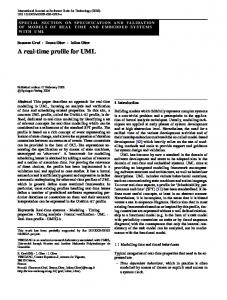
This operation adds a new instance of patient component.It is realized when a new patient arrived to the clinics. It’s worth to note that two constraints should be verified before adding a new patient component instance on the current PMS architecture. First, there is an event service that can survey the new patient (no more than five patients on the service event). Second, there is a nurse that can look after the new patient (no more than 3 patient hold on by the nurse). The modelling of these rules is given in the figure 7.
7. The existence of a patient implies a nurse existence. Hence, the system specification must consider the constraints of the Producer/Consumer style and the stated specific properties. The figure 4 describes the PMS system architecture with a description of the communication according to the Producer/Consumer style. 5
P
N
X : Event service
P
N
S
S
S
S
Z: Patient
N:Nurse
Architecture before insert_patient operation reconfiguration
P X: Event service
P
P Z’: Patient
S
S P
P S
S
Figure 7. Modelling insert patient operation Z: Patient
N:Nurse
Architecture after insert_patient operation reconfiguration
to execute. In fact, in the beginning of functioning system, architect have to add at least an event service to the system (number event service inserted depend on the number of nurses and patients to be hold). Then, architect should insert some nurses to look after our coming patients. After that, architect has the choice whether to add, delete or transfer patient, nurses or event services according to the PMS system requirements. To clarify more, figure 8 illustrates coordinating modelling aspect.
Figure 5. Architecture evolution
Figure 6. Modelling insert eventService operation
4.3
Modelling coordination aspect
This part is useful to illustrate how reconfiguration operations coordinate together in order to realise PMS architectural evolution. Moreover, this aspect enables the architect to know what what are suitable operations that are ready
Figure 8. Modelling coordination
6
5 Conclusion
[8] M. H. Kacem, M. Jmaiel, and K. Drira. Describing dynamic software architectures using an extended uml model. in Proc. of Symposium on Applied Computing, 2006. [9] M. H. Kacem, M. Jmaiel, A. H. Kacem, and K. Drira. Evaluation and comparison of ADL based approaches for the description of dynamic of software architectures. In ICEIS’05: The 7th International Conference on Enterprise Information Systems, Miami, USA, May 2005. INSTICC Press. [10] M. H. Kacem, M. N. Miladi, M. Jmaiel, A. H. Kacem, and K. Drira. Towards a uml profile for the description of software architecture. In COEA’05, The Conference on Component-Oriented Enterprise Applications, Augsburg, Germany, Septembre 2005. to be published on Springer Lecture Notes in Computer Science. [11] I. Loulou, A. HadjKacem, M. Jmaiel, and K. Drira. Approche int´egr´ee pour la sp´ecification des architectures dynamiques orient´ees composants. In Proceedings of the Eighth Maghrebian Conference on Software Engineering and Artificial Intelligence, MCSEAI’04, pages 125–136, Mai 2004. [12] I. Loulou, A. H. Kacem, M. Jmaiel, and K. Drira. Sp´ecification et v´erification des architectures dynamiques des syst`emes orient´es composants. Technical Report D´ecembre, Facult´e des Sciences Economique et de Gestion Sfax, 2003. [13] I. Loulou, A. H. Kacem, M. Jmaiel, and K. Drira. Towards a unified graph-based framework for dynamic componentbased architectures description in z. In ICPS’04: The IEEE/ACS International Conference on Pervasive Services, pages 227–234. IEEE Computer Society, 2004. [14] D. Luckham. Rapide : A language and toolset for simulation of distributed systems by partial orderings of events. In Proceedings of DIMACS Partial Order Methods Workshop IV, Princeton University, 1996. [15] O. G. Management. Uml 2.0 superstructure specification. Final adopted specification, OMG, http://www.omg.org/, Augest 2003. [16] D. L. Metayer. Describing software architecture styles using graph grammars. IEEE Transactions on Software Engineering. [17] M. E. Shin and D. Cooke. Connector-based self-healing mechanism for components of a reliable system. In DEAS ’05: Proceedings of the 2005 workshop on Design and evolution of autonomic application software, pages 1–7, New York, NY, USA, 2005. ACM Press. [18] M. Tichy, H. Giese, D. Schilling, and W. Pauls. Computing optimal self-repair actions: damage minimization versus repair time. In WADS ’05: Proceedings of the 2005 workshop on Architecting dependable systems, pages 7–6, New York, NY, USA, 2005. ACM Press. [19] R. J. van Glabbeek. Bounded nondeterminism and the approximation induction principle in process algebra. In 4th Annual Symposium on Theoretical Aspects of Computer Sciences on STACS 87, pages 336–347, London, UK, 1987. Springer-Verlag. [20] A. van Lamsweerde. Formal specification: a roadmap. In ICSE ’00: Proceedings of the Conference on The Future of Software Engineering, pages 147–159, New York, NY, USA, 2000. ACM Press.
Briefly speaking UML Language is undoubtedly the most widespread modelling language. Whereas, this Language is inappropriate for the dynamic modelling architecture. To overcome these shortcomings, we implemented a FUJABA PlugIn called “Architectural PlugIn” allowing us to model the architecture dynamics according to an UML architectural Profile. Our “Architectural PlugIn” models architecture dynamics through three major aspects : structural, dynamic and coordinated aspect. Moreover, the “Architectural PlugIn” models are syntactically and graphically validated by two different kinds of rules : Intra-model Rules and Inter-model Rules. Likewise, our “Architectural PlugIn” maps the built models to the XML language and validates the generated XML file by some integrated XML schemas in the Plugin. However the semantic aspect remains unexplored in our current work. For instance, we can’t assume that “Guards” part elements appear in the “structural feature” one. Indeed, we can’t also assume that there is no connection between “Require & Delete” part and the “insert” part. A possible prospect might cover these limits to transform the UML models into formal specification in order to prove some properties such as consistency. This work is currently under development using Z specification.
References [1] L. Bellissard, F. Boyer, M. Riveill, and J.-Y. Vion-Dury. System services for distributed application configuration. In Proceedings of 4th International Conference on Configurable Distributed Systems, Annapolis, Maryland, pages 4– 6, may 1998. [2] A. Carzaniga, E. D. Nitto, D. Rosenblum, and A. Wolf. Issues in supporting event-based architectural styles. In 3rd International Software Architecture Workshop (ISAW3), Orlando, Florida, 1998. [3] E. Cuesta, P. de la Fuente, and M. Barrio-Solorzano. A constructive development environment for parallel and distributed programs. In Proceedings of the IEEE Workshop on Configurable Distributed Systems (IWCCS’94), pages 304– 312, Mars 1994. [4] M. Endler and J. Wei. Programming generic dynamic reconfigurations for distributed applications. In Proceedings of the International Workshop Configurable Distributed Systems, pages 68–79, 1992. [5] J. Hillman and I. Warren. An open framework for dynamic reconfiguration. icse, 0:594–603, 2004. [6] D. Hirsch, P. Inverardi, and U. Montanari. Graph grammars and constraint solving for software architecture styles. In Proceedings of the Int. Software Architecture Workshop, pages 69–72, 1998. Implementation. Apache XML [7] X. Project. http://xerces.apache.org/xerces2j/javadocs/xerces2/index.html.
7