IEEE TRANSACTIONS ON NUCLEAR SCIENCE, VOL. 54, NO. 3, JUNE 2007
623
A VME-Based Readout System for the CMS Preshower Sub-Detector G. Antchev, D. Barney, W. Bialas, J. C. Da Silva, P. Kokkas, N. Manthos, S. Reynaud, G. Sidiropoulos, W. Snoeys, and P. Vichoudis
Abstract—The CMS Preshower is a fine grain detector that comprises 4288 silicon sensors, each containing 32 strips. The raw data are transferred from the detector to the counting room via 1208 optical fibres. Each fibre carries a 600-byte data packet per event. The maximum average level-1 trigger rate of 100 kHz results in a total data flow of 72 GB/s from the Preshower. For the readout of the Preshower, 56 links to the CMS DAQ have been reserved, each having a bandwidth of 200 MB/s (2 kB/event). The total available downstream bandwidth of 11 GB/s necessitates a reduction in the data volume by a factor of at least 7. A modular VME-based system is currently under development. The main objective of each VME board in this system is to acquire on-detector data from at least 22 optical links, perform on-line data reduction and pass the concentrated data to the CMS DAQ. The principle modules that the system is based on are being developed in collaboration with the TOTEM experiment. Index Terms—Data acquisition, field programmable gate arrays, optical communication.
I. INTRODUCTION
T
HE CMS Preshower [1] is a fine grain detector located in front of the endcap Electromagnetic calorimeter. Its primary function is to detect photons with good spatial resolution rejection. The detector comprises 4288 in order to perform 63 mm 63 mm silicon sensors, each of which is divided into 32 strips. Fig. 1 shows the location of the Preshower in the CMS experiment. The micromodule [1] (see Fig. 2), building unit of the CMS Preshower sub-detector, comprises a silicon sensor DC-coupled to a PCB hybrid containing the PACE3 [2] front-end electronics, all mounted on ceramic and aluminium support structures. The signals from the 32 strips of the micromodule are amplified, ns (the exact LHC shaped and sampled continuously every clock frequency is 40.08 MHz) and temporarily stored in an Manuscript received November 20, 2006; revised January 30, 2007. This work was supported in part by the program “Heraklitos” of the Operational Program for Education and Initial Vocational Training of the Hellenic Ministry of Education under the 3rd Community Support Framework and the European Social Fund. G. Antchev, D. Barney, W. Bialas, S. Reynaud, and W. Snoeys are with CERN, 1211 Geneva 23, Switzerland. J. C. Da Silva is with LIP, 1000-149 Lisbon, Portugal. P. Kokkas, N. Manthos, and G. Sidiropoulos are with the University of Ioannina, GR-45110 Ioannina, Greece. P. Vichoudis was with the University of Ioannina, GR-45110 Ioannina, Greece. He is now with CERN, 1211 Geneva 23, Switzerland (e-mail:
[email protected]). Color versions of one or more of the figures in this paper are available online at http://ieeexplore.ieee.org. Digital Object Identifier 10.1109/TNS.2007.893532
analogue memory by the PACE3. Fig. 3 illustrates a signal at the output of the preamplifier/shaper. On reception of a level-1 trigger, three consecutive time samples (on the baseline, near the peak and after the peak) per strip are multiplexed, driven out of the micromodule and digitized by a 12-bit AD41240 ADC [3] on the Preshower “system mother-board” (SMB). The digitized data from up to 4 micromodules are multiplexed and formatted in 16-bit packets by a K-chip [4] and transmitted through an optical link via the GOL [5] serializer ASIC to the Counting Room. The K-chip and GOL are also located on the SMB. Fig. 4 illustrates the on-detector data readout chain. The data transport from the 4288 micromodules of the on-detector system is achieved by 1208 optical channels. Each channel carries a 600-byte data packet per event to VME-based electronics in the counting room. The maximum average level-1 GB/s. trigger rate of 100 kHz results in a total data flow of For the readout of the Preshower, 56 links to the CMS DAQ have been reserved, each having a bandwidth of MB/s ( kB/event). setting the absolute minimum number of channels per readout board to 22. The total available downstream GB/s (56 links 200 MB/s) necessitates a bandwidth of reduction in the data volume by a factor of at least 7. This level of data reduction is feasible since the occupancy is relatively low in the Preshower - an average of about 2% (peak % at the highest pseudorapidities) at high luminosity value cm s ) and most ‘interesting’ signals (from elec( tron/photon showers) have large pulse heights-equivalent to tens or hundreds of MIPs (minimum ionizing particles). However, these signals can be spread over several strips, with the edge strips having quite low pulse-heights (few MIPs). A relatively low threshold (typically 3-sigma of the pedestal noise, equivalent to about 1 MIP in normal running) removes a majority of random (noise) hits whilst retaining virtually all real signals, including the signals in strips at the edges of clusters, which are rejection. important for photonIn order to allow maximum flexibility and upgradeability the Preshower group decided to perform all data reduction off-detector, in the counting room, using VME-based electronics. Online data reduction algorithms [6] targeted for this system have shown that reduction factors of the order of (three time larger than required) can be achieved with the expected occupancy and noise levels. This reduction factor theoretically allows the treatment of more than 60 channels per board, minimizing the number of boards and links to the CMS DAQ for
0018-9499/$25.00 © 2007 IEEE
624
IEEE TRANSACTIONS ON NUCLEAR SCIENCE, VOL. 54, NO. 3, JUNE 2007
Fig. 1. The location of the Preshower sub-detector in CMS.
Fig. 2. The micromodule.
Fig. 3. The signal at the output of the preamplifier/shaper and the three samples taken (on the baseline, near the peak and after the peak).
the readout of the detector. This manuscript focuses on the architecture/ implementation of the board for the readout of the Preshower sub-detector.
II. ARCHITECTURE For the readout of the detector, a VME-based system (namely ‘Endcap Preshower Data Concentrator Card’ or ES-DCC) is currently under development. The main objectives of this system are to acquire on-detector data from up to 36 optical links per board, perform on-line data reduction (zero suppression) and pass the concentrated data to the CMS DAQ. The relatively small number of channels per board was selected in order to maximize flexibility, including the necessity to handle higher than expected average occupancies. Fig. 5 illustrates a simplified block diagram of the ES-DCC architecture, showing the major components required: • Three FPGAs having embedded hardware deserializers compatible with the transmission protocol (Gigabit Ethernet [7]) supported by the GOL for the reception of the (36 in total) input data streams as well as sufficient logic resources for the reduction of the data volume. Twelve input data streams are treated by each FPGA. These three FPGAs will be referred-to as “reduction FPGAs.” • One FPGA for merging the zero-suppressed data coming from the 3 FPGAs performing the data reduction as well as for building the ES-DCC event. This FPGA will be referred-to as “merger FPGA.” • A link to the CMS DAQ. • A circuitry for the distribution of timing, trigger and control signals. These signals will be referred-to as TTC signals. • Three FPGAs (and sufficient memory chips) receiving the non-processed (often referred-to as ‘raw’) data from the “reduction FPGAs” for event monitoring through the VME bus. These three FPGAs will be referred-to as “spy FPGAs.” • A VME64x interface/local bus controller.
ANTCHEV et al.: VME-BASED READOUT SYSTEM
625
Fig. 4. The on-detector readout chain.
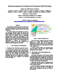
Fig. 6. A 3D model of the ES-DCC, illustrating (a) the OptoRx-12, (b) the modules comprising the ES-DCC: the host board, three OptoRx-12s and the S-Link interface to CMS DAQ and (c) the ES-DCC assembled.
Fig. 5. Simplified block diagram of the ES-DCC.
III. IMPLEMENTATION For the implementation of the readout system, the idea of a modular architecture has been adopted. The modularity allows the construction of different readout systems for multiple experiments and also maximizes flexibility for future upgrades etc. based on general purpose modules. The three principle modules that the system is based on are the following: • The OptoRx-12 [8] mezzanine card. • The VME “host board.” • The “S-Link” [9] transmitter mezzanine card. The OptoRx-12 is used to receive on-detector data from up to 12 fibres and perform the data reduction algorithms. The host board is mainly used to download all the working parameters through VME and merge the zero-suppressed data from up to three optoRx-12s. The “S-Link” transmitter mezzanine card is used to transfer the zero-suppressed data to the CMS DAQ and is the only module that existed at the start of this project. The OptoRx-12, which corresponds to one “reduction FPGA” (and the associated optical components) of Fig. 5, and the host board, that includes all the other components of Fig. 5, are two new modules developed in collaboration with the TOTEM [10] experiment. The two modules are described in the following sections.
Fig. 6 shows a 3D model of the way the three modules form the ES-DCC. It is worth mentioning that one of the advantages of the modularity of the system is the ability to handle higher occupancies by reducing the number of channels per board (by removing OptoRx-12 modules and increasing the number of host boards accordingly). A. The OptoRx-12 The OptoRx-12 is a general purpose plug-in module used for reception of optically transmitted data by gigabit applications. It is based on a 12-channel optical receiver and an FPGA from the Altera Stratix GX family with embedded hardware de-seriGbps. The FPGA emalizers qualified for data rates up to bedded de-serializers are compatible with the Gigabit Ethernet protocol/encoding. For the interconnection with the host board, the module incorporates an electrical interface (using five 64-pin PMC type connectors). The electrical interface comprises dedicated pins for powering, clocking, configuration via JTAG as well as a large number (280) of lines driven from the FPGA’s I/O pins. This large number of lines provides the de-serialized data from all 12 channels in parallel. Although the total number of interconnections is large, the physical dimensions of the OptoRx-12
626
Fig. 7. Photograph of the OptoRx-12.
Fig. 8. Block diagram of the host board.
were kept relatively small (115 mm 75 mm) allowing several of these modules to be plugged onto a VME-9U board (340 mm 360 mm). In addition, the module’s stacking height mm) is compatible with the VME mechanical specifica( tions [11]. It is worth mentioning that the module is compatible with two FPGAs of the same family having significantly different amounts of logic resources, allowing the selection of the device depending on the application. Fig. 7 shows a photograph of the module. Details about the OptoRx-12 can be found in [8]. B. The Host Board The host board is a dense design implemented in a 9U VME64x format (340 mm 360 mm). Its major components (shown in Fig. 8) are the following: • Three sets of 5 mating PMC connectors compatible with the OptoRx-12 modules. • One FPGA from the Altera Stratix family per OptoRx-12 socket (FPGA#1, #2 & #3). The number of interconnections between each FPGA and the associated set of connectors is large (216 pins).
IEEE TRANSACTIONS ON NUCLEAR SCIENCE, VOL. 54, NO. 3, JUNE 2007
• Three 18 Mb (512 K 36/1M 18) static RAMs by Cypress (CY7C1371CV25) per Stratix FPGA (MEM #1 to #9). • A high-speed USB2.0 interface by Cypress (CY7C68001) per Stratix FPGA (USB #1, #2 & #3). The USB interfaces have been included in the system mainly to provide flexibility during the commissioning phase. • An additional FPGA (FPGA#4) from the same family that shares a part (64 pins) of the 216-pin bus that interconnects the above FPGAs with the associated set of connectors. The FPGA#4 is also connected to the middle VME (J2) connector, where the S-Link mezzanine card is attached (at the back side of the VME crate). It also incorporates three static RAMs (MEM#10, #11 & #12) and a USB2.0 interface (USB#4). • An FPGA from the Altera Cyclone family configured as VME64x interface/local bus controller (FPGA#5). The local bus interconnects all the on-board FPGAs. • A TTCrx [12] ASIC and its associated chipset for receiving the TTC signals and distributing the decoded information across the board. The TTC signals are provided to the TTCrx optically and/or electrically. For the optical interface with the TTCrx, an associated optical receiver is used. Concerning the electrical interface, an additional connector in the back side of the card is used. The same connector is used to provide an extra flag that signals possible buffer overflow (trigger throttling signal). • A flexible JTAG programming interface, for reconfiguring all the on-board FPGAs, as well as the ones hosted in the plug-in modules, through either VME or JTAG download cable within a few minutes. • Two optional sockets for mezzanine cards for future use. It is worth mentioning that the host board could be adapted for use by future HEP systems. Fig. 9 shows a photograph of the host board, equipped with three OptoRx-12s. IV. FUNCTIONALITY This section gives a brief overview of the ES-DCC functionality. As mentioned previously, the primary function of the ES-DCC is to receive up to 36 input data streams (organized in bundles of 12 fibres) and to have sufficient logic resources for performing the reduction of the data volume. The first stage is the de-serialization of 12 input data streams per “reduction FPGA” (hosted in the OptoRx-12) using the embedded high speed de-serializers configured in Gigabit Ethernet mode. During normal runs, the de-serialized data are then processed (inside the same FPGA) in order to reduce their volume. The data reduction procedure includes the following functions: • Integrity check of the incoming data based on the CRC information included in the packets. The polynomial used is the , also known as CRC-16-CCITT. • De-multiplexing and de-formatting of the incoming data packets in order to extract the strip data and other information (time stamps, error flags etc.). • Subtraction of the mean value of the digitized signal when there is no particle signal present (pedestal) for
ANTCHEV et al.: VME-BASED READOUT SYSTEM
627
Fig. 10. The CMS DAQ format (64 bit wide).
Fig. 9. Photograph of the host board, equipped with 3 OptoRx-12s.
each channel. The pedestals are recalled from the CMS Conditions Database and downloaded to the ES-DCC lookup tables. • Calibration of each channel based on a predefined coefficient is performed since there is an inter-channel spread in the gain of the PACE3 pre-amplifiers. The calibration coefficients are recalled from the CMS Conditions Database and downloaded to the ES-DCC lookup tables. • Calculation and removal of the mean baseline shift of the zero signal level due to electromagnetic interference common to the channels of each micromodule (referred to as common mode). • Bunch-crossing assignment in order to remove signals from bunches not corresponding to the trigger (from previous and next events). • Selection of useful data by applying a threshold. The threshold value is calculated off-line based on the pedestal sigma and downloaded in the ES-DCC. • Collection of the sparsified data from the 12 channels organized per event. Details about the implementation of the data reduction can be found in [6]. The “merger FPGA” (the FPGA#4 of the host board) collects the reduced data for the 3 “reduction FPGAs” through the three associated 64-bit buses. The “merger FPGA” builds the ES-DCC event, according to the universal CMS DAQ format used by all CMS sub-detectors. The CMS DAQ format (shown in Fig. 10) includes, in addition to the actual sub- detector payload, information such as event type (‘Evt ty’), event number (‘LV1 id’), bunch crossing number (“BX id”), event length (“Evt lgth”), data source identifier (“Source id”), CRC information etc. The ES-DCC events are transmitted to the CMS DAQ through the attached S-Link interface card. Details
about the CMS DAQ format and the Preshower payload format can be found in [13] and [14] respectively. The large bus that connects each “reduction FPGA” with the associated “spy FPGA” (FPGAs #1, #2 & #3 of the host board) allows the transfer of the raw de-serialized data prior to the reduction procedure. The raw data are stored in the associated external memories. The stored data are read by the VME bus through the VME64x interface/local bus controller FPGA. In this way, the data flow from the detector can be monitored on request, during normal running. The same data path is used during special runs for calibration purposes, pedestal measurements etc. Finally, it is worth mentioning that all the working parameters are loaded to the “merger FPGA” and the “spy FPGAs” by the VME bus through the VME64x interface/local bus controller FPGA (FPGA#5 of the host board). Concerning the “reduction FPGAs,” the working parameters are loaded indirectly, through the private bus between them and the associated “spy FPGAs.” V. SUMMARY A VME-based readout system for the CMS Preshower subdetector is currently under development. The objective is to collect the data from the on-detector system and perform significant reduction. For the implementation of the readout system two new modules have been developed in collaboration with the TOTEM experiment: The 12-channel optical receiving plug-in module (OptoRx-12) and the VME64x-9U motherboard (host board). The performance of the OptoRx-12’s gigabit optical data reception was extensively tested this year and its behaviour deemed satisfactory. The first prototype of the host board is currently being tested. Combined tests with all the modules host boards and OptoRx-12s will follow. In total, will be produced. The system will be available in the second half of 2007. REFERENCES [1] P. Wertelaers, “ECAL preshower engineering design review,” in CMS ECAL EDR-4, vol. 2, pp. 2000–054 [Online]. Available: http://edms. cern.ch/document/115565/1
628
IEEE TRANSACTIONS ON NUCLEAR SCIENCE, VOL. 54, NO. 3, JUNE 2007
[2] P. Aspell, “PACE3: A large dynamic range analogue memory ASIC assembly designed for the readout of silicon sensors in the LHC CMS Preshower,” in Proc. 10th Workshop Electronics for LHC Experiments Conf. Rec., Boston, MA, 2004, pp. 137–141. [3] G. Minderico, C. Fachada, I.-L. Chan, K.-M. Chan, H.-M. Cheong, A. Lopes, P. Cardoso, J. Vital, K. Kloukinas, and A. Marchioro, “A CMOS low power, quad channel, 12 bit, 40MS/s pipelined ADC for applications in particle physics calorimetry,” in Proc. 9th Workshop Electronics for LHC Experiments Conf. Rec., Amsterdam, The Netherlands, 2003, pp. 88–91. [4] K. Kloukinas, “Kchip: A radiation tolerant digital data concentrator chip for the CMS preshower detector,” in Proc. 9th Workshop Electronics for LHC Experiments Conf. Rec., Amsterdam, The Netherlands, 2003, pp. 66–70. [5] P. Moreira, “G-link and gigabit ethernet compliant serializer for LHC data transmission,” in Proc. IEEE Nuclear Science Symp. Conf. Rec., Lyon, France, 2000, vol. 2, pp. 9/6–9/9. [6] D. Barney, W. Bialas, P. Kokkas, N. Manthos, S. Reynaud, G. Sidiropoulos, and P. Vichoudis, Implementation of on-line data reduction algorithms in the CMS endcap preshower data concentrator card, CMS NOTE-2006/146.
[7] IEEE, Standard 802.3, 1998. [8] S. Reynaud and P. Vichoudis, “A multi-channel optical plug-in module for gigabit data reception,” presented at the 12th Workshop Electronics for LHC Experiments, Valencia, Spain, Sep. 2006. [9] H. C. van der Bij, “S-LINK, a data link interface specification for the LHC era,” IEEE Trans. Nucl. Sci., vol. 44, no. 3, pp. 398–402, Jun. 1997. [10] TOTEM: Tech. Design Rep., CERN-LHCC-2004-002, the TOTEM collaboration. [11] IEEE, Standard 1101.1, 1998. [12] J. Christiansen, A. Marchioro, P. Moreira, and A. Sancho, “Receiver ASIC for timing, trigger and control distribution in LHC experiments,” IEEE Trans. Nucl. Sci., vol. 43, no. 3, pp. 1773–1777, Jun. 1996. [13] A. Racz, CMS DAQ Horizontal Pages [Online]. Available: http://cmsdoc.cern.ch/cms/TRIDAS/horizontal/ [14] W. Bialas, Preshower Off-Detector Data Format, CMS NOTE in preparation.