A Wideband Transconductance Amplifier for Current Calibrations
Recommend Documents
акÑÐ¸Ð²Ð½Ð¸Ñ FBAR ÑÑлÑÑÑÑв. ÐлÑÑÐ¾Ð²Ñ ... electromechanical coupling coefficient of FBAR resonators .... the expression for transconductance gm takes the form. g v.
basic analog building block OTA circuit. The designed. OTA circuit is tested in .... K. Kim, O. Kwon, J. Seo, Nano-scale Device. Modeling and Simulation: FinFET, ...
OTA-based floating voltage controlled current ... voltage and increases the output impedance. .... The Flipped Voltage Follower: A Useful Cell for Low-Voltage.
Email: [email protected]. AbstractâElectrical bioimpedance spectroscopy is a fast and relatively easily applicable method for tissue characterization.
Jun 6, 2015 - nology. In addition, the circuit suffers from body effect In this pa- .... [2] Parak, C. S.; Schaumann, R.: Design of a 4-MHz analog CMOS transcon-.
Differential-Input Buffered and Transconductance Amplifier ... and eight [10] different current-mode all-pass filters have been ... The difference of the ip and in.
and General Laboratory Use. Marc S. Litz ... 4 M. A. Ressler and J. W. McCorkle, "Evolution of Army Research Laboratory .... Battle Lab Integration & Techl Dirctrt.
Apr 23, 2010 - [9] M.Rudolph et al., Analysis of the survivability of GaN low-noise amplifiers, IEEE T. Microw. ... May 21â24, Island of Kos, Greece (2006), pag.
wideband Darlington amplifier is described. The amplifier configuration consists
of a common-emitter transistor pair with low-pass filter. The normalized gain ...
low power,RF transceivers. Introduction:- Earlier since the FCC allocated 7.5 GHz that is from 3.1 GHz to 10.6 GHz for ultra wideband. (UWB) technology ,interest ...
Our model accurately derives the currents by using accurate device threshold model based on analysis of two dimensional electron gas in the channel.
Jul 10, 2015 - Supply current = 24.0 mA at a supply voltage of 5.0 V ... Product data sheet ... VCC = 5.0 V; ZS = ZL = 5
A fully differential wideband CMOS transimpedance amplifier 1s presented. Simulation mulu o f different inductire peaking configura- tions we shown Measured ...
where Gt is the total gain of cascaded design, Gi is the gain of stage i, and the n is the number of ...... [16] Jung-Suk Goo, HIGH FREQUENCY NOISE IN CMOS. LOW NOISE ... [28] Choong-Yul Cha; Sang-Gug Lee; , "A low power, high gain.
CDNLive 2014. Tel Aviv. Israel. Talk Outline. ⢠Technion â Fraunhofer IAF Collaboration. ⢠Technology (brief). ⢠High frequency MMIC design challenges.
First works in InP technology were carried out.(Dr. Kraus PhD thesis on Sigma-Delta). The first 100nm mHEMT technology (and meanwhile the last) project was.
AbstractâThis paper presents the development of the wideband power amplifier (PA) for application to intelligent cognitive radios. The load-tracking based on ...
AbstractâLinear power amplifiers are critical components in ultrasonic imaging systems that implement chirp-coded ex- citation. Bench-top commercial power ...
posed VGA is approximately 900 MHz with a gain control range of. 94.1 dB. The proposed VGA includes a dc offset cancellation loop to avoid amplification of the ...
Finally, the design of 3D monolithic integrated inductors will be discussed. ...... Figure (4.17) Layout of proposed CMOS UWB LNA . ... PSD. Power Spectral Density. RF. Radio Frequency. RFIC. Radio Frequency Integrated Circuit. SNR.
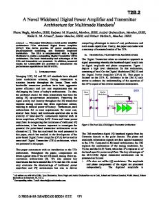
Abstract â This paper introduces a novel power amplifier architecture: âThe wide-band Digital Power Amplifier. (DPA)â. This device provides RF power ...
combining, vertically stacked balun. I. INTRODUCTION. One of the main advantages of GaN based integrated technologies is the ability to deliver a high output ...
A Wideband Transconductance Amplifier for Current Calibrations
smutâA wide-band transconductance ampliï¬er for current cali~ ons is described. The ampliï¬er will deliver a ground-referenced taut current of 5 A rms from .dc ...