1
Joint Beamforming and Transmit Diversity for WCDMA (Unclassified) Mário Marques da Silva / Américo Correia Telecommunications Institute & MOD IST, Torre Norte 11.10, Av. Rovisco Pais, 1049-001 Lisboa, Portugal Email:
[email protected] /
[email protected]
Abstract The current work develops an efficient scheme to be used for the downlink of a WCDMA network, using transmitter diversity and beamforming. The performances of space-time transmit diversity (STTD) in combination with selective transmit diversity (STD), beamforming (BF) and beam sele ctive transmit diversity (BSTD) which is a composite scheme of STD and BF, have been studied at the system level using the capacity as performance index. Both fading and interference are jointly considered in the multipath propagation environment. The main constraint was the implementation problem. It considers the use of an array with eight antenna elements spaced half wavelength per 120o sector to implement dynamically the several proposed techniques based on the environment. It was found that the comparison is strongly related to the availability of path diversity. The system capacity is maximized by the BF in the presence of multipath diversity and high multiple access interference. Otherwise it is the BSTD that achieves the best overall capacity performance. For higher data rates and small number of users the system that gives the best capacity performance is STTD+STD. Keywords - Space-time transmit diversity, selective transmit diversity, beamforming, system capacity, downlink of DS-CDMA, fading, Multiple Access Interference
1 – Introduction Battle Force communications should use DS-CDMA technology due to its high data rates, network capacity and flexibility to allow a variety of services as Internet, multimedia, data base access, video-conference, etc. It is expected that it will become more and more asynchronous with higher rhythms of transmission in the downlink than in the uplink. This is necessary for services like Internet, Data Base Access, Multimedia, etc. The downlink capacity is limited by both fast fading and multiple access interference (MAI). To improve the received signal quality at the mobile station (MS), various techniques as Multi-user Detectors (MUD) [1], transmit diversity (TD) or pre-distortion schemes have been proposed to mit igate the performance degradation due to fast fading. In [2] Alamouti has presented a new diversity scheme known as STTD. This technique is based on Space-Time Coding [3][4] and belongs to an open loop TD class, being the one that better performs for the typical urban environments. As a representative of the closed loop, STD selects the antenna with the best instantaneous channel state for signal transmission and has a reverse link to inform the transmitter about the Channel State Information (CSI) [5][6][7][8]. It is expected that STTD has a superior performance when in the presence of a multipath fading channel (urban, hilly terrain and rural scenarios), even in the presence of inter-symbol interference [5]. STD should outperform STTD for the single path fading environment (sub-urban scenario) with low signal-to-noise per symbol rate [5]. In the present work it was considered a combination of both techniques (STTD+STD). Both transmit diversity schemes require low correlation between the antennas, which can be achieved by adequate separation between the antennas. On the other hand, the received signal at the MS is also corrupted by the MAI. Making use of the spatial isolation of different users, signals by beamforming (BF) is an effective solution to solve this problem. If the radio channel has a high degree of multipath diversity, it can be beneficial (depending upon the number of active users) to employ relatively few antenna diversity branches. In CDMA systems there are typically many interferers and there are not enough degrees of freedom in the array to cancel them all. CDMA systems usually use the proposed beamforming or multibeam antennas [9].
2
In this case, the RAKE receiver already provides multipath diversity when in the presence of a several paths channel. For this reason, and because beamforming antennas will provide most of the gain in the area of MAI reduction it is generally suggested that beamforming directed towards the desired users, using algorithms such as Maximum Likelihood Sequence Estimator (MMSE) or Min imum Variance (MV) [10], should be considered for CDMA systems. To make the comparison more sufficient, another beam selective transmit diversity (BSTD) scheme is also proposed as an opponent to STTD+STD and BF. Actually, BSTD can be regarded to be a composite scheme of BF and STD, and all the array elements in BSTD are equally divided into several groups to form several sub-beamforming arrays whose antenna elements spacing is half wavelength, while the distance between adjacent sub-beamforming arrays is large enough to keep them uncorrelated. The performances are compared at the system level with capacity as performance index, and both fading and interference are jointly studied in the single path and multipath multi-user environments. The rest of the paper is organized as follows. The system and signal model for BSTD is introduced in Section 2. With low modifications, the same model can also be applicable to STD, STTD+STD and BF, since all of them are almost the extreme cases of BSTD. In Section 3, the expression of the received signal to interference plus noise ratio (SINR) is presented and the statistics of the parameters in the SINR expression are studied as well. The system outage probability calculation is elaborated in Section 4, as well as capacity calculations, and corresponding numerical results are presented in Section 5. Finally, conclusions are drawn in Section 6.
2 – System and Signal Models In this section, a baseband system model is presented for the analysis of the proposed beam selective transmit diversity (BSTD) scheme, in which several sub-beamforming arrays are equipped at the same BS and they are combined to implement the selective transmit diversity technique. BSTD scheme can be viewed as a composite of the beamforming (BF) scheme and the selective transmit diversity (STD) scheme and, with low modifications, can also be viewed as the proposed STTD+STD. The performance comparison of STTD+STD, BSTD and BF in later sections will be based on this model.
MS1 H11 (t)
HK1(t)
...
...
H k (1 ) 1 (t )
V1H (t )
... 1 2 ... Mb
pa ⋅ s1 (t )
W1
...
P ower Divider
...
...
1 2 ... Mb
W1
...
Power Divider k(1) th SBFA
1st SBFA
...
1 2 ... Mb P ower Divider Kth SBFA
... BS pt ⋅ s1 (t)
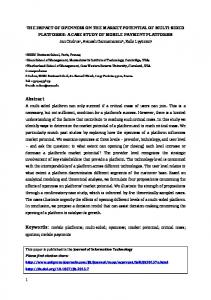
Fig. 1 – Base station configuration for BSTD
W1
3
There is a total of N Mobile Stations (MS) randomly distributed along the arc boundary of a 120º cell sector, and the nth MS is denoted to be MSn for n=1,…,N. The BS configuration for BSTD is shown in Fig.1. There are K sub-beamforming arrays (SBFA) equipped at the Base Stations (BS) for this cell sector. Each SBFA has an antenna elements spacing of half wavelength, while the distance between adjacent SBFAs is large enough to keep them uncorrelated. The array element number in each SBFA is Mb and thus the total element number of the K SBFAs is M=Mb xK. Without loss of generality, we will describe the multipath channel model for the 1st and the same model is also applicable to other N-1 users. It is assumed that the k(1)th SBFA results in the best channel state for the 1st user and thus is selected to form a beam toward the desired MS1 as shown in Fig.1. Here, k(1) represents the index of the SBFA selected by the 1st user. The impulse response of the multipath channel between the k(1)th SBFA and the MS1 can be modeled as:
(
L
)
l l H k (1 ) 1 (t ) = ∑ α k ( 1) 1 ⋅ Λ (θ1 ) ⋅ δ t − τ k (1 ) 1 , l =1
L
∑ α l =1
2
l k
(1 )
1
(1)
L
= g/L = g ∑ l =1
(2)
[
Λ (θ 1 ) = 1, e jπ sinθ1 ,..., e j( M b −1)π sinθ1
]. T
(3)
It is assumed that H k (1 ) 1 ( t ) contains L independently faded multipath components. The zero mean complex Gaussian random variable α k ( 1) 1 represents the complex fading amplitude of the lth signal path in H k (1) 1 (t ) . l
If uniform power delay profile is considered, the average path strength E α kl ( 1) 1 will be equal to g/L for each signal path as shown in (2), where the factor g represents the average channel gain and is equal to the sum of all the L signal paths average strengths. The matrix Λ (θ1 ) only introduce a phase shift, although, there exist beamforming algorithms that can also introduce an amplitude attenuation component. The δ (t) 2
in (1) is the delta function and the discrete path delays τ k (1) 1 , l = 1,..., L , are supposed to be separated more than one chip duration from one another, and thus the L paths can be resolved by the mobile Rake receiver in the delay domain. l
4
4T 3T 2T T 0 S 4 S 3 S2 S1
Antenna 1
S 3* -S 4* S 1* -S 2*
Antenna 5
1
Pilot
2 1 2 3
FBI 4 3
4
Antenna 2
Pilot
Antenna 6
Pilot
Antenna 3
Pilot
Antenna 7
Pilot
Antenna 4
Pilot
Antenna 8
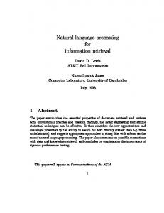
Fig. 2 – Configuration of STTD+STD Fig.2 shows the proposed configuration of STTD+STD, which is a hybrid scheme that employs the Alamouti scheme (open loop class) with Feedback Indication (FBI) about the state of the Rayleigh fading channel (close loop class). Within this scheme, only the two ‘best’ antennas transmit information and signalling data while the others antennas only transmit signalling data at a lower bit rate (e.g., an overhead of 10%). The total received signal at the MS1 can be expressed as: N
r1 (t ) = d11 (t ) + ∑ i n1 (t ) + n1 (t )
(4)
n =2
L
N
L
= ∑ α k (1 ) 1. pt .M b .s1 (t − τ k (1 ) 1 ) + ∑∑ α k ( n ) 1. pt .M b .ξ n1 .sn (t − τ k ( n ) 1) + n1 (t ) l
l =1
l
l
l
(5)
n = 2 l =1
where n1(t) represents the complex white Gaussian noise of the receiver.
3 – Expression and Statistics of the SINR Expression In most DS-CDMA system, orthogonal Walsh code is adopted for the downlink transmission. However, in the multipath rich environment with path delay separation with more than one chip duration, the orthogonality of the Walsh code would be difficult to be maintained and the performance should be close to that of the random code. Since the number of orthogonal codes is limited, the use of non-orthogonal codes can also be a choice for the 3G WCDMA systems. For the reasons mentioned above, the random spreading code is assumed in this analysis. Moreover, the Rake receiver with maximum ratio combining (MRC) is supposed to be employed at each MS, and the expression of the total signal received by the Rake receiver at the MS1 is given by (5). If the self-interference in each Rake finger is ignored, the SINR at the Rake combiner output can be shown as:
5
L
∑α
Γ1 =
l =1
l k (1 ) 1
2
. pt .M b (6)
L 2 1 N ⋅ ∑ ξ n1∑ α kl ( n ) 1 . pt .M b + σ n2 G' n = 2 l =1 L 2 p .M α kl ( 1) 1 . t 2 b ∑ σn Ψ1 l =1 = = N L N 2 p .M 1 1 ⋅ ∑ ξ n1 ∑ α kl ( n ) 1 . t 2 b + 1 ⋅ ∑ ξ .Φ + 1 G ' n= 2 l =1 σn G' n = 2 n1 n
where σ n2 denotes the noise power per Rake finger, and the pseudo processing gain G’ is defined as G’=1.06G=1.06 Ts /Tc ,Ts and Tc are the data symbol duration and the chip duration respectively, while G represents the system processing gain and the factor 1.06 is due to raised cosine pulse shape with roll-off factor 0.22 [1]. When Mb >1, the beam pattern can be generated and the ?n1 can be modeled as a function of the angle difference θ n − θ1 . The beamwidth BW and the side lobe level SLL are used to model the 3 dB beamwidth of the main beam and the effect of the side lobe, respectively. In such “key hole” array gain pattern, the gain is assumed to be unitary when the MS1 falls in the angular range of [θ n − BW / 2,θ n + BW / 2] , otherwise it is approximated to be SLL. Before studying the statistics of Ψ1 and Φ n , we firstly introduce a new random variable Xk1 as: L
X k 1 = ∑ α kl1 . 2
l =1 L
where
∑α
l 2 k1
pt .M b , σ n2
(7)
denotes the sum of the L fading path gain in H k 1 (t ) , which is the channel between the MS1
l =1
and the arbitrary kth SBFA of the total K SBFAs in fig.1, and the factor
pt .Mb can firstly be regarded as a σ n2
constant. According to [11], the probability density function (pdf) of Xk1 can be written as:
f X k1 ( X k1 ) =
L−1
−
Xk 1 T
X k 1 .e , ( xk 1 ≥ 0), T L .( L −1)!
(8)
2 p .M g p .M T = E α kl1 . t 2 b = ⋅ t 2 b σn L σn
(9)
2 Here, the average path strength E α kl 1 is equal to g/L for all l as defined in (2).
In the BSTD scheme, the SBFA selection is similar to the antenna selection in STD, and the SBFA resulting in the best channel state for the desired user is selected for signal transmission. Specifically, the sum of the L fading path gain of the selected channel H k (1 ) 1 ( t ) in fig.1 should be the maximum among those of all the K
candidate channels {H k 1( t ), k = 1,..., K } . Here, the sele ction is assumed to be perfect and without delay and error. Therefore, the ? 1 defined in (6) will also be the maximum of the set {X k 1 (t ), k = 1,..., K }:
6
L
Ψ1 = ∑ α kl (1 ) 1 ⋅ 2
l =1
pt .M b = max{X k 1, k = 1,..., K } α n2
(10)
Since the channel states of different users are uncorrelated, the channel H k ( n ) 1 (t ) can be randomly selected
from the set {H k 1( t ), k = 1,..., K } in fig.1 as seen from the MS1 , and thus the Φ n defined in (6) will also be equivalent to the one randomly selected from the set {X k 1 (t ), k = 1,..., K }: L
φ n = ∑ α kl ( n ) 1 ⋅ 2
l =1
L
where
∑α l =1
2
l k
(n )
1
pt ⋅ M b = rand {X k 1, k = 1,..., K } α n2
(11)
denotes the sum of the L fading path gain in H k ( n ) 1 (t ) . Moreover, it is assumed that the
probability of being selected to be Φ n is equal to
1 (uniform distrib ution) for every X k 1 . K
4 – Expressions of Outage Probability The outage probability is defined as the probability that the received SINR Γ1 is lower than certain threshold
η: η
P{Γ1 ≤ η } = ∫ f Γ (γ 1 ) ⋅ dγ 1,
(12)
1
0
where η is a positive number. With the Gaussian approximation for MAI the outage probability for N>>1 can be approximated as:
1 − E 1 | Ψ Γ 1 +∞ η 1 1 ⋅ f (ψ ) ⋅ dψ , P{Γ1 ≤ η } ≅ ∫ ⋅ erfc Ψ1 1 1 0 2 1 2 ⋅ V | Ψ1 Γ1
(ψ 1 ≥ 0),
(13)
where the specific fΨ1 (ψ 1 ) is dependent on L, being for L=1: ψ − 1 dP ( Ψ1 ≤ ψ 1 ) K f Ψ1 (ψ 1 ) = = ⋅ 1 − e T dψ 1 T
and for L=2:
K −1
⋅e
ψ − 1 T
(ψ 1 ≥ 0) .
(14)
7
ψ − 1 dP(Ψ1 ≤ ψ 1 ) f Ψ1 (ψ 1 ) = = K ⋅ 1 − e T dψ 1
ψ ⋅ 1 + 1 T
K −1
⋅
ψ 1 − ψT1 ⋅e T2
(ψ 1 ≥ 0).
(15)
1 1 | Ψ1 and V | Ψ1 are also dependent on L. Γ1 Γ1
The expressions of E
5 – Numerical Results 5.1 Parameters in the outage probability calculation The results shown in the present paper were done considering two different classes of services and for each one, two different levels of multiple access interference (MAI) to allow different le vels of QoS : 1. First, we consider the data service, where can be considered up to 7 users in each cell. In this situation we consider a data rate of 768 Kbps, and the required signal to noise ratio is Eb /No =1 dB with a processing gain of G=4. It is considered two different levels of MAI (or QoS) MI=(N+I)/N, where N is the noise power (AWGN) and I is the interference power, namely MI=3 dB and MI=5 dB, leading to Eb /(No +NI)=-2 dB and Eb /(No +NI)=-4 dB (lower required QoS), respectively; 2. Second, we consider the voice service, where can exist up to 130 users in each cell. In this situation we consider a data rate of 12.2 Kb/s, and the required signal to noise ratio is Eb /No =5 dB with a processing gain of G=128. As in the case of data, it is also considered two different le vels of QoS, which corresponds to MI=3 dB and MI=5 dB, leading to Eb /(No +NI)=2 dB and Eb /(No +NI)=0 dB. 5.2 Comparison of outage probability performance The theoretical system outage probability was calculated for different user number N. In Fig.3, it is firstly assumed that the link SNR is equal to 1dB and only one fading path (L=1) exists in the channel defined in (1). Moreover, to make a fair comparison, the number of total array elements is kept as 8 for all the compared schemes. The KxMb =1x8 BF represents a single beamforming array with 8 elements, while in the 2x4 BSTD, 2 sub-beamforming arrays with 4 elements in each are employed for spatial diversity. Since twobranch spatial diversity is the most common view in practical system, the number of sub-beamforming arrays is fixed to be two (K=2) for the BSTD in the following analysis. Finally, the 8 array elements are combined into 4 arrays with 2 elements widely separated to form a transmit diversity array in the 4x2 STTD+STD.
8
Probability of Outage of Space-Time Schemes 0.25
STTD+STD BF BSTD
+-+-+ o-o-o x-x-x
Outage Probability (Pe)
0.2
MI=3dB
_____
MI=5dB
-- ---
0.15
0.1
0.05
0 1
2
3
4
5
6
7
Number of Users (Nu)
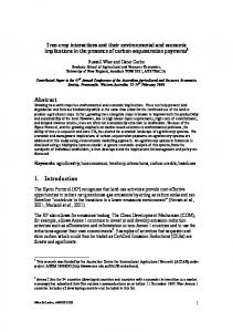
Fig. 3 – Outage Probability performance for the data service and single fading path per channel (L=1)
In fact, the Outage Probability (OP) is affected by both the fading and the interference in the DS-CDMA system. As show in Fig.3, the STTD+STD achieves the lowest OP among the 3 schemes when Nu