DUQUE, E.P.N. AND G.R. SRINIVASAN Numerical simulations of a hovering rotor using embedded grids. ... noise predictions using. Kirchhoff methods. Journal ...
NLR-TP-2000-420
Accurate and efficient vortex-capturing for a helicopter rotor in hover O.J. Boelens, H. van der Ven, B. Oskam and A.A. Hassan
NLR-TP-2000-420
Accurate and efficient vortex-capturing for a helicopter rotor in hover O.J. Boelens, H. van der Ven, B. Oskam and A.A. Hassan*
* The Boeing Company (Mesa)
This investigation has been carried out under a contract awarded by the Boeing/McDonnell Douglas Helicopter Company, Purchase Order Number 689578. The Boeing Company (Mesa) has granted NLR permission to publish this report. This report is based on a presentation to be held at the 26th European Rotorcraft Forum, The Hague, the Netherlands, September 26-29, 2000. The contents of this report may be cited on condition that full credit is given to NLR and the authors.
Division: Issued: Classification of title:
Fluid Dynamics August 2000 unclassified
-3NLR-TP-2000-420
Summary A numerical method has been developed for predicting from first principles, the complex vortexwake for a helicopter rotor in hover. The method is based on the solution of the three-dimensional, compressible Euler equations expressed in an Arbitrary Lagrangian Eulerian (ALE) reference frame. A second-order accurate discontinuous Galerkin (DG) finite-element method is used to discretize the governing equations on a hexahedral mesh. Unstructured, local mesh refinement is performed to enable prediction of the structure of the vortex wake while computational efficiency is retained through a mesh de-refinement process. Convergence acceleration is achieved using a multi-grid technique. While this study emphasizes the wake system for a hovering rotor, the developed method, when applied on a dynamically-deforming mesh, is equally applicable for predicting the vortex-wake for a rotor in forward flight. Accuracy of the predictions are assessed using the wind tunnel data for the two-bladed Caradonna-Tung rotor in hover. This report has been presented at the 26 lands, September 26-29, 2000.
��
European Rotorcraft Forum, The Hague, The Nether-
-4NLR-TP-2000-420
Contents List of figures
6
1
Introduction
9
1.1
Lifting-line/lifting-surface methods
9
1.2
Full potential methods
9
1.3
Euler and Navier-Stokes methods
10
1.4
Outline of paper
10
2
3
CFD algorithm
11
2.1
Discontinuous Galerkin method
11
2.2
Unique features
11
2.3
Standard features
11
2.4
Vortex sensor and vortex grid adaptation
12
Extensions for rotor in hover simulations
13
3.1
Boundary conditions for rotor in hover
13
3.2
Rotor in hover as steady state problem
13
4
Accuracy and efficiency
14
5
Transonic unsteady rotor Navier-Stokes(TURNS)
15
6
Test case
16
7
Caradonna-Tung rotor in hover
17
7.1
Caradonna-Tung OH-grid
17
7.2
Caradonna-Tung multi-block grid
17
7.3
Caradonna-Tung CH-grid
18
7.4
Caradonna-Tung surface pressure results
18
7.5
Vortex persistence for Caradonna-Tung rotor
18
7.6
Need for extension to Navier-Stokes
19
8
Discussion
20
-5NLR-TP-2000-420
9
Concluding remarks
(32 pages in total)
21
-6NLR-TP-2000-420
List of figures Figure 1
The Caradonna-Tung grid near the blade (726,784 elements): (a) the blade and the plane trough the leading edge, trailing edge and blade tip, (b) the blade and a grid plane perpendicular to the blade. The rotor blade is colored grey. The block boundaries are indicated as red lines.
Figure 2
26
The upper part of the Caradonna-Tung grid (726,784 elements): (a) the complete grid, (b) detail near the rotor blade. The rotor blade is colored grey. The block boundaries are indicated as red lines.
Figure 3
27
The lower part of the Caradonna-Tung grid (726,784 elements): (a) the complete grid, (b) detail near the rotor blade. The rotor blade is colored grey. The block boundaries are indicated as red line.
Figure 4
Comparison of -
��
-distribution for the Caradonna-Tung helicopter rotor in
hover (collective pitch: 12 � , � Figure 5
28
������������ �� �� ��� �� � , � � �
)
29
Vorticity contours at different radial cross-section for the Caradonna-Tung helicopter rotor in hover on (a) the medium adapted grid (135,280 elements) and on (b) the fine grid (726,784 elements) (collective pitch: 12 � ,
�� �
Figure 6
� � � ��
).
30
The medium adapted Caradonna-Tung grid (135,280 elements). Shown are the periodic plane at z=0 and the plane at x=-3.6.
Figure 7
31
Iso-contour of the vorticity for the Caradonna-Tung helicopter rotor in hover on the fine grid (726,784 elements) (collective pitch: 12 � , �
Figure 8
�� ��� �� �
).
31
Predicted and experimental vortex trajectories of Caradonna-Tung rotor in hover on the medium adapted grid (135,280 elements) and fine grid (726,784 elements) (collective pitch: 12 � , �
�� ��� �� �
).
32
-7NLR-TP-2000-420
Nomenclature
Symbols �� � �
Freestream speed of sound
�
����� �� �� � � � �� � � �� �� � ���
Pressure coefficient
� ��� ��
Coordinate directions (scaled with � )
Greek symbols �
Element width in computational direction �
�
Tip Mach number Rotor blade tip radius Reynolds number
Velocity vector (scaled with � )
Vorticity ( ��� ) Angular frequency of rotor [rpm]
-8NLR-TP-2000-420
This page is intentionally left blank.
-9NLR-TP-2000-420
1 Introduction It is well known that the prediction of the aerodynamic performance of a helicopter in hover is dependent on one’s ability to accurately predict its complex vortex wake. To assess the impact of improved airfoil designs, novel blade twist and blade planform on rotor performance, it is essential to consider a tool that can accurately predict the wake system from first principles. Not only will such a tool be beneficial for a rotor in hover, but it will also be of considerable benefit for predicting the wake system for a rotor in forward flight. In the following paragraphs, we briefly summarize the advantages and the limitations of the available hover prediction methods with special attention to wake predictions. 1.1 Lifting-line/lifting-surface methods In integral lifting-line formulations (Refs. 15, 18) the blade is usually represented by a straight line and its vortex wake by a user-prescribed rigid helix. In this formulation, empirical expressions that emulate the radial contraction of the wake as it convects below the rotor are used. Moreover, in addition to prescribing a vortex core radius, a core model is also needed to allow for the computation of the vortex-induced velocity field at control points on the blade. In general, the empirical expressions are derived from experimental data for the rotor blade or from a geometrically similar or close derivative. Extension of the lifting-line formulation for a hovering rotor to a lifting-surface one was performed by Kocurek and Tangler (Ref. 17) - nonetheless, all limitations remained the same. Lifting surface formulations (Refs. 6, 20) that represent the rotor and its free wake system, though more comprehensive than lifting-line formulations, also suffer from the need to specify the vortex core radius. Unfortunately, while both formulations are computationally efficient, their application is usually limited to simple blade geometries where the airfoil aerodynamic characteristics are a priori known. The later restriction is inherent in both ’inviscid’ formulations, which require a table look-up procedure to determine the aerodynamics of the airfoil(s) that constitute the blade. 1.2 Full potential methods In methods that are based on the full potential formulation, two distinct approaches are adopted for predicting the free wake geometry of a hovering rotor. In the method by Ramachandran et al. (Ref. 22), the wake trajectories are computed using a Lagrangian approach where tracer particles are released at the tip of the blade and then tracked as they freely convect throughout the computational domain. In his method, a parameter that defines the spread of vorticity to the grid points surrounding the different tracer particles is prescribed by the user. In essence, this parameter can be viewed as being equivalent to the specification of the vortex core radius
- 10 NLR-TP-2000-420
in lifting-line/lifting-surface formulations. In 1995, Bagai (Ref. 3) developed a finite-difference method that solved the vorticity transport equation for the convection of linear vortex filaments that are released from the trailing edge of the blade. In his method, a vortex core model was also used. Despite the ability of full potential-based methods to predict the wake geometry for a rotor in hover, they still suffered from the need to specify a vortex core radius (or and equivalent parameter). Of course, in these inviscid models, distortion of the vortex core and its subsequent effect on the strength of the vortex were not accounted for. 1.3 Euler and Navier-Stokes methods In recent years, more comprehensive models that are based on the solutions of the Euler (Ref. 26) and the Navier-Stokes equations (Refs. 1, 14, 23, 29) were developed. The prime objective was to develop solution methods that had minimum reliance on user input while providing the necessary accuracy. In principle, though these formulations are sufficient for capturing the details of the vortical flow field, excessive numerical diffusion, especially in regions far from the blade, limited their application. To minimize numerical diffusion, researchers embarked on adopting one, or more, strategies. Namely, the use of higher-order numerical schemes (Ref. 14), the use of overset (or Chimera) grid systems to resolve the details of the wake away from the blade (Refs. 1, 29) and the use of adaptive gridding schemes that are natural for unstructured grid flow solvers (Refs. 12, 16). Among these three strategies, wake capturing through adaptation of an unstructured grid proved to be the most effective - typically, not requiring excessively large grids as with structured grid flow solvers. 1.4 Outline of paper In this paper we demonstrate the unique features and the accuracy of a new rotor solver with unstructured, local mesh refinement for capturing the wake of a rotor in hover. First the main features of the discontinuous Galerkin (DG) finite element method are outlined. Special attention is paid to the vortex sensor and vortex grid adaptation. Some of the extensions applied to the DG method to be able to simulate the flow field for a helicopter rotor in hover are discussed next. The capabilities of the flow solver in simulating the flow field of a hovering rotor are demonstrated by simulations for the two-bladed Caradonna-Tung rotor. A special grid around the CaradonnaTung rotor is generated. A complete section is dedicated to the description of this grid. Accuracy of the developed method, as contrasted to the accuracy of a conventional Reynolds Averaged Navier-Stokes (RANS) flow solver is addressed and comparisons with the wind tunnel data for the two-bladed Caradonna-Tung rotor is made. The vortex persistence for the Caradonna-Tung rotor is illustrated by showing iso-contours of the vorticity for a fine grid without adaptation. Finally, concluding remarks are made.
- 11 NLR-TP-2000-420
2 CFD algorithm 2.1 Discontinuous Galerkin method The DG flow solver is based on a discontinuous Galerkin finite element discretization of the unsteady Euler equations (Refs. 9, 10, 30). Discontinuous Galerkin finite element methods use a discontinuous function space to approximate the exact solution of the Euler equations. A short introduction to these DG methods is provided by the lecture notes of a NATO/VKI special course on ’Higher Order Discretization Methods in CFD’ (Ref. 9). An overview of DG methods, including review articles, can be found in the lecture notes of the first International Symposium on DG methods (Ref. 10), which was held in May 1999. 2.2 Unique features A unique feature of second-order accurate discontinuous Galerkin finite element methods is that equations are solved not only for the mean flow field, but also for the flow field gradients. This results in a very compact scheme, because it is not necessary to reconstruct a flow field gradient, necessary to achieve second order accuracy, using data in neighboring elements. Carrying the flow field gradients as explicit, dependent variables implies that the vorticity is carried as a dependent flow variable. The present finite element method has shock capturing capabilities and is easy to parallelize because there is limited communication between neighboring elements. The local behavior of the present finite element method is also beneficial for grid adaptation, which is done using unstructured grid refinement. At this point it should be remarked that unstructured element-by-element grid refinement is utilized in the present research to recover an isotropic grid from an anisotropic, initial grid. The DG finite element method has an inherent ability to handle adaptivity strategies since the refining and de-refining of the grid is done without taking into account the continuity restrictions typical of conventional CFD methods (Refs. 30, 32). The anisotropy of the initial grid is often a concomitant feature of efficient, structured grids. 2.3 Standard features Dynamic motions can be simulated using a rigidly translating-rotating reference frame connected to the configuration. This requires some modifications to the discontinuous Galerkin finite element method defined in an inertial frame, of which the most important one is the incorporation of the grid velocity in the flux formulation using an Arbitrary Lagrangian Eulerian (ALE) formulation. Using a Space-Time formulation the ALE DG method can be extended for simulation of arbitrarily moving multiple bodies, such as helicopter rotors in forward flight. The discretization in time is based on an implicit time integration method. The use of an implicit
- 12 NLR-TP-2000-420
time integration method is necessary, because there exists a very large discrepancy in time step imposed by stability constraints and the necessary time step for sufficient accuracy due to very small grid sizes, for example close to sharp wing edges. The non-linear equations of the implicit time integration method are solved using a FAS multigrid method. 2.4 Vortex sensor and vortex grid adaptation Different quantities can be used to identify vortices within a flow, for example the total pressure
loss, the vorticity magnitude ( � , where � is the vorticity �
��
� ), and the helicity (
).
In this paper the vortex sensor based on the vorticity has been used to define a vortex grid adaptation sensor. The general idea behind this vortex grid adaptation sensor is that to minimize the numerical diffusion of the vorticity and numerical dissipation in a vortex the grid within the vortex should be as isotropic, as uniform and as refined as possible. For each computational direction the following vortex grid adaptation sensor is defined. The sensor for computational direction � equals the vorticity times
�
�
for elements with
�
�
larger than a specified value. Here
�
�
is the ele-
ment width in computational direction � . For the other elements the vortex grid adaptation sensor equals zero. All elements with a vortex grid adaptation sensor not equal to zero are refined in the
� -direction to obtain a more isotropic, uniform and refined grid in the vortex.
- 13 NLR-TP-2000-420
3 Extensions for rotor in hover simulations The extension of the DG flow solver algorithm developed for fixed wing aircraft to the simulation of rotor in hover flows consists of two steps, which will be discussed in this section. 3.1 Boundary conditions for rotor in hover An improved far field boundary conditions for hover simulations can be derived using one-dimensional helicopter momentum theory (Refs. 24, 27). In this method the rotor is described as an actuator disc and the far field wake velocity is calculated using actuator disc theory. The wake velocity obtained from actuator disc theory induces a mass flux which must be balanced by an opposite mass flux through the inflow boundaries. This mass flux is assumed to be uniformly distributed over a sphere of radius r located at the center of the rotor disc. The thus obtained inflow velocity is added to the inflow boundary condition, resulting in an improved far-field boundary condition. In this analysis it is assumed that the flow field is incompressible and the helicopter rotor is approximated as an actuator disc with a constant loading. This hover boundary condition requires as input the rotor disc center and radius, the center of the rotor wake at the outflow boundary and a known thrust coefficient. 3.2 Rotor in hover as steady state problem A helicopter rotor in hover can be considered as a steady state problem when the Euler equations are formulated in a reference frame rotating with the same angular velocity vector as the helicopter rotor. This requires less computational effort than the solution of the equivalent time-accurate problem. When defining the rotor in hover condition as a steady state problem, i.e. by using a single rotating reference frame, an additional source term accounting for the Coriolis force is introduced into the Euler equations (Ref. 7).
- 14 NLR-TP-2000-420
4 Accuracy and efficiency As opposed to ’Chimera’ or Overset grid techniques conservation of flux variables is easily accomplished in Arbitrary Lagrangian Eulerian methods since a single, time-varying grid is used. Combined with a discontinuous Galerkin discretization, ALE methods provide a powerful CFD technology for rotor wake analysis. The distinguishing CFD key features of the current algorithmic approach are that the flow field gradients are carried as explicit, dependent flow variables and that the DG algorithm is capable of element-by-element h-refinement. The DG algorithm allows this h-refiment on an element-byelement basis without any special algorithmic components for hanging edges and vertices. Conventional CFD algorithms cannot handle hanging edges and vertices without considering them as special cases. The present second-order accurate DG algorithm remains accurate without special consideration of hanging entities. Standard multigrid acceleration techniques can be applied to achieve a computationally efficient algorithm, since the discontinuous Galerkin method allows explicit time integration schemes for steady state problems. The same multigrid algorithm can be used in an implicit time integration scheme for time-dependent problems. Moreover, since the discontinuous Galerkin method is extremely local, parallelization by grid partitioning requires minimal communication overhead and excellent speed-ups of 11.5 out of 14 are obtained on the NLR NEC SX-4/16 parallel vector super computer (Ref. 31). The present simulations are performed on the NLR NEC SX-5/8 parallel vector super computer.
- 15 NLR-TP-2000-420
5 Transonic unsteady rotor Navier-Stokes(TURNS) In the present research the results obtained with the DG flow solver are compared with those obtained using the TURNS flow solver (Refs. 13, 25, 28, 33). TURNS stands for Transonic Unsteady Rotor Navier-Stokes, and is based on a finite difference, upwind numerical algorithm. Unlike the DG flow solver, the TURNS flow solver has been developed specifically for helicopter rotor applications. In TURNS an upwind-biased flux-difference scheme (originally suggested by Roe, later extended to three-dimensional flows by Vatsa) is used to evaluate the inviscid fluxes. Second- or third-order accuracy has been established by using the Van Leer MUSCL approach using flux limiters in order to be total variation diminishing (TVD). Standard second-order central differencing is used for the discretization of the viscous flux terms. The LU-SGS method which is a direct modification of the approximate lower-diagonal-upper (LDU) factorization to the unfactored implicit matrix is used as the time-marching procedure. A modified finite-volume method is used to calculate the metrics. The space metrics are evaluated at grid points instead of cell interfaces in order to be compatible with the finite difference numerical scheme. The time metrics are evaluated in the same manner as in a finite difference scheme. For more details of the TURNS algorithm, see Ref. 25.
- 16 NLR-TP-2000-420
6 Test case The rotor flow simulation capabilities of the DG flow solver are tested against the standard CaradonnaTung experiment. The Caradonna-Tung experiment was conducted at NASA Ames and consists of a two-bladed helicopter rotor in hover (Ref. 8). The rotor employs two cantilever-mounted, manually adjustable blades. These blades have a NACA-0012 profile and are untwisted and untapered. The blade aspect ratio of the Caradonna-Tung rotor is 6. At five radial sections, viz.
�
�
=0.5, 0.68, 0.8, 0.89
and 0.96, pressure transducers were located. The experiments were performed for collective pitch settings of 0 � , 2 � , 5 � , 8 � and 12 � , and angular frequencies
�
ranging from 650 to 2540 rpm. For
the case discussed in the present paper, a collective pitch setting of 12 � , an angular frequency of 1750 rpm and a tip Mach number �
�
�� �����
��� � �� �
, with �
�� �
�� �
of 0.61 were used. Here the tip Mach number is defined as
the rotor blade tip radius and �
the free stream speed of sound.
- 17 NLR-TP-2000-420
7 Caradonna-Tung rotor in hover 7.1 Caradonna-Tung OH-grid At NLR a single-block grid of one half of the computational domain containing one blade of the Caradonna-Tung helicopter rotor was available. For this grid the rotor blade is in the center of the computational domain and connected to an axis where a slip flow boundary condition is applied. The grid has an O-topology around the blade and a H-topology parallel with the blade. The blade tip was square with a finite thickness in the experiment, but is reduced to zero thickness in the last cell in order to facilitate the grid generation process. For a figure of this grid, see Ref. 19, Bild 21, OH-Netz f¨ur einen zweibl¨attrigen Rotor in Schwebeflug. Simulations on this grid showed that, although giving the correct pressure distribution on the rotor blade and the correct thrust coefficient, the grid is insufficient to correctly capture the tip vortex over a distance of one-and-a-half revolutions. The insufficiency of this single block OH-grid pertains in particular to the grid quality near the blade tip; to allow for a quantum jump in grid quality the blade tip geometry has been comple-
mented with a cap (by revolving the NACA0012 tip profile around its � -axis). 7.2 Caradonna-Tung multi-block grid
For the present study a special multi-block grid has been generated. The grid point distribution on the rotor blade of the Caradonna-Tung helicopter rotor is taken to resemble the grid point distribution on the rotor blade in the existing, OH-type Caradonna-Tung grid as close as possible. The multi-block topology around the blade is illustrated in Figs. 1(a) and 1(b). Since the tip vortex moves both inward and downward (see for example Figure 9 of Ref. 11), special attention was given to this region of the grid. In this region a grid with as uniform as possible elements has been generated, also in the circumferential direction, see Figs. 2(b) and 3(b). The control over the location of the grid points below the rotor blade is facilitated by introducing an additional set of blocks below the rotor blade (compare Figs. 2(a) and 3(a)). Since the tip vortex moves downward more elements are located below the rotor than above the rotor. Near the outflow boundary the aspect ratio of the elements in the flow direction is increased to obtain a large amount of numerical dissipation resulting in a destruction of the vortex so that no interaction between the vortex and the outflow boundary condition is expected to occur, see Fig. 3(a). The resulting multi-block grid of one half of the computational domain consists of 55 blocks, with a total of 726,784 elements and 823,599 grid points (fine grid). However, simulations may also be performed on a one-time coarsened grid, i.e. with a total of 90,848 elements (medium grid).
- 18 NLR-TP-2000-420
7.3 Caradonna-Tung CH-grid The grid used by the TURNS flow solver has a C-topology around the blade and a H-topology parallel with the plane of the blade. The grid used has 299 grid points in the wraparound C-direction, 71 points in the spanwise direction and 61 points in the normal direction. The total number of grid
�
points in this grid equals 299 � 71 � 61 1,294,969. The grid is initially generated using a hyperbolic grid generator and is then curved in the azimuth direction to provide for periodicity near the zero and
�
�
azimuth positions. The grid extends one rotor radius beyond the blade tip in the
spanwise direction, and also one rotor diameter above and below the plane of the rotor. 7.4 Caradonna-Tung surface pressure results The flow field around the Caradonna-Tung helicopter rotor using a collective pitch setting of
� and a tip Mach number � ��
of
�� �
�� �
has been simulated by using the DG solver on the medium
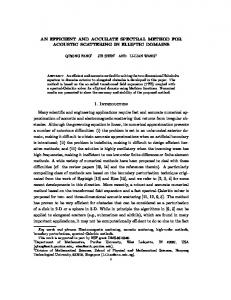
grid with grid adaptation and on the fine grid without grid adaptation. The DG results are compared with those obtained using the TURNS flow solver on the CH-grid. Note that the medium grid originally contains 90,848 elements, that the fine grid contains 726,784 elements and that the TURNS grid contains 1,261,600 cells. After adaptation the medium grid contains 135,280 elements. In Fig. 4 the -
��
-distribution at five radial stations obtained by the simulations is compared with
the experimental data (Ref. 8). The agreement between the DG flow solver simulations and the experimental data is generally good. The pressure peak at the lower side of the rotor blade is, however, resolved better on the fine grid. The agreement between the DG flow solver results and the TURNS flow solver results on the upper side of the rotor is fair; the DG flow solver resolves the pressure peak better. At the lower side the TURNS results have a �
�
-value higher than the
experimental value, which does not seem to be consistent with earlier results (Ref. 25). The DG flow solver results coincide very well with the experimental pressure data at the lower side. 7.5 Vortex persistence for Caradonna-Tung rotor Figs. 5(a) and 5(b) present the vorticity for different radial cross-sections, i.e.
� � �� � ,
,
and
��� �
behind blade 1, for both the medium grid with adaptation and the fine grid without adaptation. Comparing the DG results with and without adaptation at the 140 � azimuth position behind blade 1 shows that adaptation improves the vortex signature in terms of vorticity. Fig. 7 shows two iso-contours of the vorticity for the fine grid. From this figures it is clear that the DG flow solver is able to capture the tip vortex over a distance of one-and-a-half revolution. Figs. 5(a) and 5(b) show that the same conclusion holds for the medium adapted grid. The local behavior of the grid adaptation is presented in Fig. 6. Here, rotor blade 1, the periodic plane at �
�
and the plane at �
�
���
��
are shown. Clearly visible are the places where the
- 19 NLR-TP-2000-420
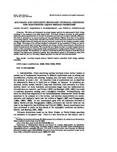
vortex intersects these planes. At those positions one can see that the grid has been adapted to obtain a grid as isotropic and as uniform as possible in the vortex. In Fig. 8 the predicted and experimental vortex trajectories of the Caradonna-Tung helicopter rotor in hover on the medium adapted grid and on the fine grid are compared. The solid black squares indicate the experimental data from Ref. 8. The computed vortex trajectories were obtained using cross-sections (see for example Fig. 5) at azimuthal increments of
��
�
to locate the centers of
vortices graphically. Both the radial position (upper set of lines) and the vertical position (lower set of lines) of the vortex are shown for azimuthal angles ranging from
�
to
�
�
, i.e one-and-a-
half revolution. The agreement between the vortex trajectories of the simulation on the medium adapted grid and on the fine grid are good, especially for azimuthal angles smaller than �
�
. The
predicted vertical position (z) of the tip vortex shows excellent agreement with the experimental one, especially for azimuthal angles larger than
�� �
�
. The radial contraction of the tip vortex
is overpredicted on both the medium adapted grid and the fine grid. This is attributed to the overprediction of the strength of the tip vortex by Euler methods (see for example also the results presented in Ref. 21). The tip vortex thus induces too high inward velocities for larger azimuthal angles. The medium adapted grid, with an improved vortex signature, i.e. a stronger vortex over a longer range of azimuthal angles, also shows a larger contraction. 7.6 Need for extension to Navier-Stokes The number of adaptation levels has been limited, since adaptation in the vortex core would only result in an unbounded increase of the vortex resolution. This unboundedness of the Euler solution in vortex cores near the tip of a blade is a direct consequence of the fact that the Euler equations are strictly non-diffusive. Total lack of diffusion results in unboundedness of the vorticity under grid refinement. Introduction of Navier-Stokes equations with a finite diffusivity will eliminate this unboundedness, and will allow grid refinement until all finite gradients are well resolved. The extension of the DG method to Reynolds-averaged Navier-Stokes equations for turbulent
airfoil flows using a two-equation k-� Rebay (Ref. 4, 5).
turbulence model has been demonstrated by Bassi and
- 20 NLR-TP-2000-420
8 Discussion In this paper the DG finite element algorithm based on an ALE formulation in conjunction with unstructured grid refinement of hexahedral grids has been used for the simulation of rotor wake vortices. It has been shown that this method is able to capture the tip vortex of the Caradonna-Tung helicopter rotor (collective pitch:
� �� �
both on a fine grid ( � �
in the vortex ( �
�
��
� � �� � � , � ��
) over a distance of one-and-a-half revolution,
elements) and a medium grid with local unstructured grid refinement
elements). Local grid adaptation is found to improve the vortex signature
in terms of vorticity. Comparison with the experimental data is generally good. The presented discontinuous Galerkin approach has the following features that make the method well suited for the simulation of rotor wake vortices: (a) the second-order accurate DG method carries the spatial flow field gradients as explicit, dependent variables implying that the vorticity is carried as a dependent flow variable; vorticity components are implicitly related to the three spatial gradients of the state vector (15 variables per element), (b) the algorithm allows degenerate, high-aspect ratio elements near leading and trailing edges for efficiency, (c) the algorithm has an extremely compact stencil, and as a result possesses an inherent ability to handle adaptive strategies since the refining and de-refining of the elements (grid) is done without any need to consider special continuity requirements typical of conventional CFD methods, and (d) the algorithm has an excellent parallelization potential because the communication between neighboring elements is strictly limited to the flow data exchange at common faces, and will therefore be well suited for parallel computing platforms. Furthermore, it should be noted that an extension of the DG algorithm from the Euler to the NavierStokes equations is feasible without compromising items (a) through (d) above, e.g. see Ref. 2 for an analysis in two dimensions. Finally, it is remarked that, while in the present paper the emphasis has been on the simulation of the wake system for a hovering rotor, the developed method, when applied on a dynamicallydeforming mesh, is equally well suited for predicting the vortex-wake for a rotor in forward flight.
- 21 NLR-TP-2000-420
9 Concluding remarks The main issue explored in the present paper is the ability of the discontinuous Galerkin finite element approach to capture the tip vortex of a hovering rotor over large distances (with and without grid adaptation). The conclusion is that the present DG algorithm can capture the tip vortex of a hovering rotor over large distances, provided the multi-grid iterations are continued until all the residuals of the
�
non-linear, algebraic equations per element are sufficiently converged. For the
Caradonna-Tung test case it is found that the convergence tolerance required for the accurate capture of trailing vortices is significantly tighter than the equivalent convergence tolerance needed to capture transonic shock waves; i.e. transonic shock waves are easy to capture relative to the far field signature of trailing vortices. When applied to a dynamically-deforming mesh, the DG method is equally applicable for the predicting the vortex-wake for a rotor in forward flight. Comparison of results of the present DG method (with and without adaptation) with the results of more conventional algorithms shows that the present DG approach yields the same or better agreement between CFD and experimental data in terms of surface pressures on a rotor blade in hover and vortex trajectories. To assess the relative computational efficiency of the DG approach (with grid adaptation) in comparison with more conventional CFD algorithms, one would need to identify a common vortex persistence problem and compare the required computational resources at the Navier-Stokes level for equal vortex signatures at large distances. This assessment of relative computational complexity of DG algorithms with grid adaptation for stiff problems remains as a challenge for future projects. Provided such an assessment of the computational complexity of the proposed algorithm can be concluded successfully, one can conclude that the proposed combination of standard ALE formulation with the unconventional DG finite-element method (including grid adaptation) can meet the basic requirements for CFD algorithms that need to be satisfied if one wishes to establish standard and reliable CFD tools for vortex prediction.
- 22 NLR-TP-2000-420
Acknowledgements The authors would like to acknowledge the support of the Royal Netherlands Air Force (RNLAF, contract number N98/19), The Boeing Company, Mesa and NLR; we also like to thank S.P. Spekreijse and H.A. Sytsma of the NLR for making the Caradonna-Tung grid, and J.J.W. van der Vegt of the University of Twente, Enschede, The Netherlands for his contributions to the DG flow solver algorithm.
- 23 NLR-TP-2000-420
References 1.
A HMNAD , J.
AND
R. S TRAWN May 1999 Hovering Rotor and Wake Calculations with
an Overset-Grid Navier-Stokes Solver. Paper presented at the 55
��
Annual Forum of the
American Helicopter Society. 2.
ATKINS , H.L. AND C.W. S HU 1999 Analysis of the Discontinuous Galerkin method to the Diffusion Operator. AIAA paper 99-3306.
3.
BAGAI , A.
AND
J.G. L EISHMAN Rotor Free-Wake Modeling Using a Pseudo-Implicit
Technique - Including Comparisons with Experiment. Journal of the American Helicopter Society, Vol. 40, No. 3, July 1995. 4.
BASSI , F. AND S. R EBAY A High Order Discontinuous Galerkin Method for Compressible Turbulent Flows. In Discontinuous Galerkin Methods, Lecture Notes in Computational Science and Engineering 11, B. Cockburn, G.E. Karniadakis and C.-W. Shu (Eds.), Springer Verlag, 1999.
5.
BASSI , F.
AND
S. R EBAY GMRES Discontinuous Galerkin Solution of the Compressible
Navier-Stokes Equations. In Discontinuous Galerkin Methods, Lecture Notes in Computational Science and Engineering 11, B. Cockburn, G.E. Karniadakis and C.-W. Shu (Eds.), Springer Verlag, 1999. 6.
B LISS , D.B.
AND
W.O. M ILLER Efficient Free Wake Calculations Using Analyti-
cal/Numerical Matching and Far-Field Linearization. Paper presented at the 45
��
Annual
Forum of the American Helicopter Society, May 1989. 7.
B ONIFACE , J.C.
AND
J. S IDES Numerical simulation of steady and unsteady euler flows
around multibladed helicopter rotors. Paper presented at 19
��
European Rotorcraft Forum
Cernobbio, Como, Italy, 1993. 8.
C ARADONNA , F.X.
AND
C. T UNG Experimental and Analytical Studies of a Model Heli-
copter Rotor in Hover. NASA Technical Memorandum 81232, 1981. 9.
C OCKBURN , B. Discontinuous Galerkin methods for convection-dominated problems. In High-order methods for computational physics, Lecture Notes in Computational Science and Engineering 11, T. Barth and H. Deconinck (Eds.), Springer Verlag, 1999.
10.
C OCKBURN , B., K ARNIADAKIS , G.
AND
C.-W. S HU An overview of the development
of discontinuous Galerkin methods. In Discontinuous Galerkin Methods, Lecture Notes in Computational Science and Engineering 11, B. Cockburn, G.E. Karniadakis and C.-W. Shu (Eds.), Springer Verlag, 1999. 11.
C ONLISK , A.T. The Fluid Dynamics of Rotor Wakes: Theory, Computation and Experiment. AIAA paper 99-3421, 1999.
- 24 NLR-TP-2000-420
12.
D INDAR , M., L EMNIOS , A., S HEPARD , M., JANSEN , K.
AND
D. K ENWRIGHT Effect
of Tip Vortex Resolution on UH-60A Rotor Blade Hover Performance Calculations. Paper presented at the 54 13.
D UQUE , E.P.N.
��
Annual Forum of the American Helicopter Society, June 1998.
AND
G.R. S RINIVASAN Numerical simulations of a hovering rotor using
embedded grids. Paper presented at the 48
��
Annual Forum of the American Helicopter
Society, 1992. 14.
H ARIHARAN , N. First-principles Based High Order Methodologies for Rotorcraft Flowfield Studies. Paper presented at the 55
��
Annual Forum of the American Helicopter Soci-
ety, Montreal, Canada, May 1999. 15.
J OHNSON , W. Rotorcraft Aerodynamics Model for a Comprehensive Analysis. Paper presented at the 54
16.
K ANG , H.J.
��
Annual Forum of the American Helicopter Society, May 1998.
AND
O.J. K WON Numerical Prediction of Rotor Hover Performances Using
Unstructured Adaptive Meshes. AIAA paper 2000-0258, January 2000. 17.
KOCUREK , J.D.
AND
J.L. TANGLER A Prescribed Wake Lifting Surface Hover Perfor-
mance Analysis. Journal of the American Helicopter Society, Vol. 22, No. 1, January 1977. 18.
L ANGREBE , A.J. The Wake Geometry of a Hovering Helicopter Rotor and its Influence of Rotor Performance. Journal of the American Helicopter society, Vol. 17, No. 4, October 1972.
19.
PAHLKE , K. Berechnung von Str¨omungsfeldern um Hubschrauberrotoren im Vorw¨artsflug durch die L¨osung der Euler-Gleichungen. Forschungsbericht 1999-22, Deutsches Zentrum f¨ur Luft- und Raumfahrt e. V., 1999.
20.
Q UACKENBUSH , T.R., B LISS , D.B.
AND
D.A. WACHSPRESS New Free Wake Analysis
of Rotorcraft Hover Performance Using Influence Coefficients. Journal of Aircraft, Vol. 26, No. 12, December 1989. 21.
¨ R ADDATZ , J., S CH ONING , B., K ROLL , N., ROUZAUD , O., B ONIFACE , J.-C.
AND
J.
S ID E` S Validation and Assessment of DLR and ONERA Euler Codes for Multibladed Rotors in Hover. IMT Project AERO-2017/2060 Rotorcraft Aerodynamics and Aeroacoustics HELISHAPE, November 1996. 22.
R AMACHANDRAN , K., T UNG , C. AND F.X. C ARADONNA Rotor Hover Performance Prediction Using A Free Wake Computational Fluid Dynamics Method. Journal of Aircraft, Vol. 26, No. 8, December 1989.
23.
S RINIVASAN , G.R. AND W.J. M C C ROSKEY Navier-Stokes Calculations of Hovering Rotor Flowfields. Journal of Aircraft, Vol. 25, No. 10, October 1988.
24.
S RINIVASAN , G.R., R AGHAVAN , V.
AND
E.P.N. D UQUE Flowfield analysis of modern
helicopter rotors in hover by Navier-Stokes method. Paper presented at the International
- 25 NLR-TP-2000-420
Technical Specialists Meeting on Rotorcraft Acoustics and Rotor Fluid Dynamics Philadelphia, PA, USA, 1991. 25.
S RINIVASAN , G.R., BAEDER , J.D., O BAYASHI , S. AND W.J. M C C ROSKEY Flowfield of a lifting rotor in hover: A Navier-Stokes simulation. AIAA Journal, 30, 2371–2378, 1992.
26.
S TANGL , R.
AND
S. WAGNER Euler Procedure for Calculation of the Steady Rotor Flow
with Emphasis on Wake Evolution. AIAA paper 90-3007, 1990. 27.
S TRAWN , R.C.
AND
T.J. BARTH A finite volume Euler solver for computing rotary-wing
aerodynamics on unstructured meshes. Journal of the American Helicopter Society, 61–67, 1993. 28.
S TRAWN , R.C., B ISWAS , R.
AND
A.S. LYRINTZIS Helicopter noise predictions using
Kirchhoff methods. Journal of Computational Acoustics 4, 321–339, 1996. 29.
S TRAWN , R.C.
AND
J. A HMAD Computational Modeling of Hovering Rotors and Wakes.
AIAA paper 2000-0110, January 2000. 30.
VAN DER
V EGT, J.J.W.
AND
H.
VAN DER
V EN Discontinuous Galerkin finite element
method with anisotropic local grid refinement for inviscid compressible flow. J. Comput. Phys. 140, 1–32, 1998. 31.
VAN DER
V EN , H.
AND
J.J.W.
VAN DER
V EGT Experiences with advanced CFD algo-
rithms on NEC SX-4, In Parallel Processing VECPAR ’96, Palma and Dongarra (Eds.), Lect. Notes in Computer Science, Springer Verlag, 1997. 32.
VAN DER
V EN , H. AND J.J.W.
VAN DER
V EGT Accuracy, Resolution, and Computational
Complexity of a Discontinuous Galerkin Finite Element Method. Lecture Notes in Computational Science and Engineering 11, Springer Verlag, 1999. 33.
W ISSINK , A.M., LYRINTZIS , A.S., S TRAWN , R.C., O LIKER , L.
AND
R. B ISWAS Ef-
ficient helicopter aerodynamic and aeroacoustic predictions on parallel computers. AIAA paper 96-0153, 1996.
- 26 NLR-TP-2000-420
X Z Y
(a) X Y Z
(b) Fig. 1
The Caradonna-Tung grid near the blade (726,784 elements): (a) the blade and the plane trough the leading edge, trailing edge and blade tip, (b) the blade and a grid plane perpendicular to the blade. The rotor blade is colored grey. The block boundaries are indicated as red lines.
- 27 NLR-TP-2000-420
X
Y Z
(a) X
Y Z
(b) Fig. 2 The upper part of the Caradonna-Tung grid (726,784 elements): (a) the complete grid, (b) detail near the rotor blade. The rotor blade is colored grey. The block boundaries are indicated as red lines.
- 28 NLR-TP-2000-420
X
Z Y
(a) X
Z Y
(b) Fig. 3
The lower part of the Caradonna-Tung grid (726,784 elements): (a) the complete grid, (b) detail near the rotor blade. The rotor blade is colored grey. The block boundaries are indicated as red line.
- 29 NLR-TP-2000-420
NLR medium grid with adaption NLR fine grid BOEING MESA using TURNS EXPERIMENT
2.5
NLR medium grid with adaption NLR fine grid BOEING MESA using TURNS EXPERIMENT
2.5
1.5
1.5
1
1
Cp
2
Cp
2
0.5
0.5
0
0
-0.5
-0.5
r/R=0.50
-1 0
0.25
0.5
0.75
r/R=0.68
-1
1
0
0.25
X
0.75
1
X
NLR medium grid with adaption NLR fine grid BOEING MESA using TURNS EXPERIMENT
2.5
0.5
NLR medium grid with adaption NLR fine grid BOEING MESA using TURNS EXPERIMENT
2.5
1.5
1.5
1
1
Cp
2
Cp
2
0.5
0.5
0
0
-0.5
-0.5
r/R=0.80
-1 0
0.25
0.5
0.75
r/R=0.89
-1
1
0
0.25
X
0.5
0.75
1
X
NLR medium grid with adaption NLR fine grid BOEING MESA using TURNS EXPERIMENT
2.5 2 1.5
Cp
1 0.5 0 -0.5
r/R=0.96
-1 0
0.25
0.5
0.75
1
X
� -distribution for the Caradonna-Tung helicopter rotor in hover (collective ��� �� � ������������ � �� pitch: 12 � , � , ��� )
Fig. 4 Comparison of -
- 30 NLR-TP-2000-420
1
1
1
1
0
0
0
0
-1
-1
-1
-1
-3
-4
-5 4
5
6
-3
-4
7
-5 4
-2
0.4 0.36 0.32 0.28 0.24 0.2 0.16 0.12 0.08 0.04 0
5
6
0.4 0.36 0.32 0.28 0.24 0.2 0.16 0.12 0.08 0.04 0
-3
-4
-5 4
7
-2
x
0.4 0.36 0.32 0.28 0.24 0.2 0.16 0.12 0.08 0.04 0
x
-2
x
x
-2
5
6
0.4 0.36 0.32 0.28 0.24 0.2 0.16 0.12 0.08 0.04 0
-3
-4
7
-5 4
5
6
7
r
r
r
r
20 � behind blade 1
70 � behind blade 1
100 � behind blade 1
140 � behind blade 1
(a) medium adapted grid (135,280 elements) 1
1
1
1
0
0
0
0
-1
-1
-1
-1
-3
-4
-5 4
5
6
-3
-4
7
-5 4
-2
0.4 0.36 0.32 0.28 0.24 0.2 0.16 0.12 0.08 0.04 0
5
6
0.4 0.36 0.32 0.28 0.24 0.2 0.16 0.12 0.08 0.04 0
-3
-4
-5 4
7
-2
x
0.4 0.36 0.32 0.28 0.24 0.2 0.16 0.12 0.08 0.04 0
x
-2
x
x
-2
5
6
0.4 0.36 0.32 0.28 0.24 0.2 0.16 0.12 0.08 0.04 0
-3
-4
7
-5 4
5
6
7
r
r
r
r
20 � behind blade 1
70 � behind blade 1
100 � behind blade 1
140 � behind blade 1
(b) fine grid (726,784 elements) Fig. 5
Vorticity contours at different radial cross-section for the Caradonna-Tung helicopter rotor in hover on (a) the medium adapted grid (135,280 elements) and on (b) the fine grid (726,784 elements) (collective pitch: 12 � ,
� � �� � � ��
).
- 31 NLR-TP-2000-420
X Y Z
Vortex blade2 Vortex blade 1 Blade 1 Vortex blade 2
Fig. 6 The medium adapted Caradonna-Tung grid (135,280 elements). Shown are the periodic plane at z=0 and the plane at x=-3.6.
�
� � � � �
� � �
Fig. 7 Iso-contour of the vorticity for the Caradonna-Tung helicopter rotor in hover on the fine grid (726,784 elements) (collective pitch: 12 � ,
��� �� � � ��
).
- 32 NLR-TP-2000-420
6
-6
Radial position (r) -5
5
-4
experiment medium grid with adaption fine grid
3
-3
2
-2
z
r
4
Vertical position (z) 1
0
Fig. 8
-1
0
100
200
ψ
300
400
500
0
Predicted and experimental vortex trajectories of Caradonna-Tung rotor in hover on the medium adapted grid (135,280 elements) and fine grid (726,784 elements) (collective pitch: 12 � ,
��� �� � � ��
).