Accurate Non-Iterative Fault Location Algorithm for Three-Terminal Line
Recommend Documents
Abstract: This paper presents a new approach to fault location on power
transmission lines. This approach uses two-end unsynchronised measurements
of.
25 Mar 2008 ... Author Abdelsalam Mohamed Elhaffar. Name of the dissertation. Power
Transmission Line Fault Location based on Current Traveling Waves.
in HVDC transmission lines using Artificial Neural Networks. ..... transmission lines under unsynchronized two-end measurement and uncertain line parameters ...
C.G., India ... in HVDC transmission lines using Artificial Neural Networks. ... Keywords: ANN, fault location, HVDC transmission line, PSCAD/EMTDC.
additional data coming from the lightning detection network can be ... In Section 3, the automated improved transmission line ..... Baud rate of 115200 bits per ...
Keywords: Fault Location, Neural Networks, Transmission Line, Wavelet ... Simulink/MATLAB and its associated toolboxes: Simulink, SimPowerSystems and ...
A novel method for on-line fault detection and location ... implementing such mechanisms for the on-chip data ... error recovery scheme is implemented based on.
Mar 24, 2014 - for UHV overhead Transmission line by using GA-ANFIS. .... An algorithm for fault detection and classification of low impedance faults ... in a transmission line based on RMS value of phase currents and zero sequence current.
Some of them such as representing transmission lines by either first or .... where O1i is membership function of μAi (x) and A is the linguistic label .... Fig. 2. Single line diagram of system model. 4.3. Accurate fault location using ANFIS ... The
transmission line. ... series compensation, simulation, two-end unsynchronized meas- urement. ...... The 300 km, 400 kV double-circuit transmission line com-.
Abstract: In this paper. a novel fault location algorithm based on phasor measurement units (PMUs) for series compensated lines ;has been proposed ...
Jul 11, 2006 - the singularity of the sheath impedance matrix. Sang-Won Min · Soon-Ryul Nam · Sang-Hee Kang ·. Jong-Keun Park. Received: 15 April 2006 ...
Oct 7, 2011 - tion algorithm for long transmission lines compensated by a series flexible ac transmission systems (FACTS) device. In the proposed algorithm ...
New Fault-Location Algorithm for Transmission. Lines Including Unified Power-Flow Controller. Mahdi Ghazizadeh Ahsaee and Javad Sadeh, Member, IEEE.
Use of cable lines and combined overhead transmission lines with underground ... and are not influenced by source impedance, fault resistance and power flow [11]. ... tive and zero in overhead and cable sections is subject to complex- ity. Ref. [1] o
is proportional to the horizontal acceleration of the COG its second integral does represent the horizontal position of the gravity line. (GLP). However, the initial ...
This paper presents an accurate fault location algorithm for a double-circuit transmission line with series capacitor compensation at its both ends. Use of ...
Transmission line is a key to power transmission, also the point which causes .... In this experiment, we use Simulink in Matlab to create a simulation system.
[email protected]. Abstract. This paper deals with the technique designated to location of faults in untransposed lines. The algorithm capable ...
Abstract-In this paper, we propose a multiphase March-like algorithm for partial and full diagnosis of all simple static faults in static Random Access Memories, ...
niques such as SWAT that capture how hardware faults man- ifest to the system level .... lation completes, the computed data is written to a dedicated response pipe from ...... ware recovery, can buffer 1000s of instructions, but can be expanded ...
Studies and simulations in an EMTP-RV en- vironment for the 25 kV power distribution system of. Canada were carried out by considering ten types of faults with ...
www.ccsenet.org/mas. Modern Applied Science ... E-mail: [email protected]. Al-Mofleh Anwar ... E-mail: [email protected]. Faisal Y. Alzyoud.
E-mail: [email protected] ... use digital signal processing methods which take time ... rithms are based on digital signal processing principles.
Accurate Non-Iterative Fault Location Algorithm for Three-Terminal Line
Accurate location of faults on overhead power lines for the inspection-repair purpose ... locator. However, all are based on an impedance principle, making use of the .... for three-phase balanced fault: the positive-sequence (j-th kind) and ...
Accurate Non-Iterative Fault Location Algorithm for Three-Terminal Line Jan Izykowski, Eugeniusz Rosolowski Wroclaw University of Technology, Wybrzeze Wyspianskiego 27, 50-370 Wroclaw, Poland [email protected], [email protected] Abstract This paper presents a new fault location algorithm for threeterminal line, which utilises unsynchronised measurements of three phase currents and voltages from three line terminals. The algorithm consists of three subroutines designated for locating faults on particular line sections. The valid subroutine is indicated with use of a selection procedure. The distributed parameter line model is strictly considered for formulating all subroutines. The calculations are simple and do not involve iterative calculations. The presented results of the ATP-EMTP evaluation prove the validity of the fault location algorithm and its high accuracy.
1. Introduction Accurate location of faults on overhead power lines for the inspection-repair purpose [1]–[8] is of vital importance for operators and utility staff for expediting service restoration, and thus to reduce outage time, operating costs and customer complains. Different fault location algorithms for three-terminal lines (Fig. 1), have been developed so far [1]–[7]. They differ each other mainly with respect to the applied input signals of the fault locator. However, all are based on an impedance principle, making use of the fundamental frequency voltages and currents. In [1] usage of synchronised measurements of currents and voltages from all three terminals has been considered. Distributed parameter models of the line sections have been utilised there. Use of three-end unsynchronised measurements of currents and voltages has been considered in [2, 3]. The lumped models of the line sections were applied in [2]. With the aim of improving fault location accuracy, in [3] the distributed parameter models of the line sections were taken into considerations. Yet another utilisation of three-end unsynchronised measurements has been proposed in [4], where exchange of minimal amount of information between the line terminals over a protection channel was considered. Use of incomplete three-end measurements for fault location on three-terminal lines was considered in [5]–[7]. In particular, a demand and importance of developing fault location algorithms utilising only two-end synchronised measurements of voltages and currents has been stated in [5]. Complete immunity to saturation of current transformers (CTs) was proposed in [6], where use of voltage signals alone was considered for fault location. In [7] use of three-phase currents from all three line terminals and additionally three-phase voltage from the terminal at which the fault locator is installed, has been proposed. Such specific availability of measurements has been assumed with the aim of simple supplementing of the fault location function into current differential relays protecting a three-terminal line [7].
In this paper, a new algorithm, which utilises unsynchronised measurements of three phase currents and voltages from all three terminals, is presented. It is assumed, that analytical synchronisation of such measurements has to be performed, possibly without resorting to synchronising with use of the prefault measurements. In order to assure high accuracy of fault location, the distributed parameter line model is strictly utilised. The approach from [3] also takes into consideration such model, however, the presented here algorithm surpasses the method from [3] in simplicity of the needed calculations. The involved unknowns: synchronisation angles and the distance to fault, are determined here in simple non-iterative calculations. Obtaining such simplicity of calculations was possible by basing the presented here algorithm on the approach from [8], where accurate and at the same time simple fault location algorithm designed for two-terminal line, has been introduced. The paper starts with derivation of the fault location algorithm. Then, the sample results of the through ATP-EMTP [9] based evaluation of the algorithm are presented and discussed.
2. Basics of Fault Location Algorithm The circuit diagram of a three-terminal line for considering the three-end unsynchronised fault location algorithm is presented in Fig. 1. Different kinds of symmetrical components of the signals are processed in the algorithm. In general, the sequence type is considered as the i-th type, in Fig. 1 marked with the subscript i. Then, this type is assumed accordingly. In Fig. 1 the phasors of the signals measured the line end B are taken as the base, while the measurements from the buses A and C have to be analytically synchronised, with use of the synchronisation operators e j A and e j C , respectively. The fault can occur at any of three line sections (faults: FA, FB or FC in Fig. 1). The distance to the particular fault, counted from the particular bus (A, B or C) up to the fault point, is marked as: dA, dB, dC, respectively. There are three hypotheses regarding placement of the fault, and in consequence of that also three calculation subroutines for locating those hypothetical faults. Judgement on selecting the valid subroutine, which gives the result consistent with the actual fault, is finally performed.
3. Fault Location Algorithm for Two-Terminal Line All three subroutines of the presented fault location algorithm are based on the two-end unsynchronised fault location algorithm presented in [8]. Therefore, the considerations start with giving the basics of the cited approach. The algorithm from [8] utilises jointly both the j-th and k-th symmetrical components, and considers strictly the distributed parameter model of a two-terminal line (Fig. 2).
I-154
FC
C
dC
SYSTEM C
I Ci e j C
V Ci e j C
A
FB
FA dA
SYSTEM A
B
dB
SYSTEM B
I Ai e j A
T
I Bi
V Ai e j A
V Bi
Fig. 1. Fault location on three-terminal line using three-end unsynchronised measurements
S
F
I S j ( k ) e j d [p.u.]
R
A jk (e j ) 2 + B jk e j + C jk = 0
I R j(k )
where: the coefficients, calculated with using both: j-th and k-th sequence components, are: A jk = G j S k − G k S j ,
(1 – d ) [p.u.]
V S j ( k ) e j
V R j (k )
B jk = G j T k + H j S k − G k T j − H k S j ,
Fig. 2. Unsynchronised two-end fault location considering distributed parameter model of faulted line
C jk = H j T k − H k T j ,
G j(k ) = V S
The input signals of the two-end unsynchronised fault location algorithm [8] are: V S j ( k ) , V R j ( k ) , I S j ( k ) , I R j ( k ) – voltage and current phasors from the terminals S and R, respectively, for the j-th and k-th sequences of the symmetrical components. In particular, it was proposed to utilise simultaneously: for unsymmetrical faults: the positive-sequence (j-th kind) • and negative-sequence (k-th kind) components, • for three-phase balanced fault: the positive-sequence (j-th kind) and superimposed positive-sequence (k-th kind) components (note: ‘superimposed’ means: ‘fault quantity’ minus ‘pre-fault quantity’). Digital measurements of the phasors from two line ends are considered as the unsynchronised. The measurements from the terminal R are assumed as the base, while the phasors from the end S are analytically synchronised – with use of the synchronisation operator, which is a complex number: e jδ = cos( ) + j⋅ sin( )
(2)
(1)
The unknowns of the fault location algorithm are: d – distance to fault, counted from the bus S (p.u.), – synchronisation operator. For the line S-R of the length A [km], the surge impedance Z c1 and the propagation constant 1 , as for the positive-
sequence, are only required. This is so, since for all the considered kinds of sequences, the line impedance parameters become identical and are as for the positive-sequence. In [8] the quadratic compact formula for the synchronisation operator, in which the unknown distance to fault (d) is not involved, was derived. It was obtained with considering the distributed parameter line model. The formula is as follows:
H
,
j (k )
= sinh( γ A ) Z c1 I R
j (k )
1
S j ( k ) = − Z c1 I A T
j(k )
j(k )
− cosh( γ A ) V R 1
j (k )
,
,
= sinh( γ A ) V R 1
j(k )
j (k )
− cosh( γ A) Z c1 I R 1
j(k )
.
Solution of the quadratic formula (2) gives two solutions for the synchronisation operator ( e j I , e j II ), and thus two values for the synchronisation angle (δI, δII). One of the determined values of the synchronisation angle (δI or δII) is valid (δv), i.e. is consistent with the actual angle. Selection of this valid solution can be performed with using the unique solution for the synchronisation operator, derived for the lumped line model [8]: e
j lump.
= cos( lump. ) + j ⋅ sin( lump. )
(3)
where: cos( δ lump. ) =
C j Bk − C k B j A j B k − Ak B j
, sin( lump. ) =
A j C k − Ak C j A j B k − Ak B j
,
A j ( k ) = imag[Z 1L ((V R j ( k ) − Z 1L I Rj ( k ) ) I S j ( k ) − V S j ( k ) I R j ( k ) )] , *
*
*
B j ( k ) = real[− Z 1L ((V R j ( k ) − Z 1L I R j ( k ) ) I S j ( k ) + V S j ( k ) I R j ( k ) )] , *
*
*
C j ( k ) = imag[ − Z 1L ((V R j ( k ) − Z 1L I R j ( k ) ) I R j ( k ) − V S j ( k ) I S j ( k ) )] , *
*
*
Z 1L – total positive-sequence line impedance, x* – conjugate of x .
The value of the synchronisation angle obtained from (2): δI or δII, which is closer to the unique solution (3), is selected as the valid solution (δv).
I-155
The determined valid solution of the synchronisation angle (δv) is then applied for making analytical synchronisation of the measurements acquired asynchronously. Having the measurements already synchronised, one can determine the distance to fault. When processing the positive-sequence components (analogously is for the other kinds of symmetrical components) one uses the following formula [1]:
N 1 = V R1 cosh(γ A) − Z c1 I R1 sinh(γ A) − V S1e j v ,
j A
V Bi
V TBi = V TCi e j C
1
C
D1 = V R1 sinh(γ A) − Z c1 I R1 cosh(γ A) − Z c1 I S1e j v , 1
1
V S1e j v , I S1e j v – phasors of the positive-sequence voltage and
I Ci e j C
b)
current at the end S, analytically synchronised to the respective phasors from the end R.
Fig. 3 presents the circuit diagrams for the i-th sequence (where the i-th sequence could be considered as the j-th or k-th sequence) for deriving three subroutines: SUB_A (Fig. 3a), SUB_B (Fig. 3b), SUB_C (Fig. 3c). In the circuits, the measured signals are specified and additionally the currents, voltages transferred analytically towards the tap point T (the signals marked with the dashed line boxes) are included. Analytical transfer of currents and voltages is accomplished with applying the distributed parameter model for the line sections. For example, in the case of the subroutine SUB_A (Fig. 3a) the transfer across the whole unfaulted line section B-T (of the length A LB ) is performed according to: V TBi = V Bi cosh(γ A LB ) − Z c1 I Bi sinh(γ A LB )
(5a)
−V Bi sinh( γ A LB ) + I Bi cosh( γ A LB ) 1 1 Z c1
(5b)
1
1
The other analytical transfers in the circuits of Fig. 3 are to be performed analogously to (5a)–(5b). Making such transfers allows to determine one of the unknown synchronisation operator. For example, in the case of the subroutine SUB_A one can compare the voltages at the tap point T – obtained from the two transfers: V TBi (across the section B-T), V TCi e j C (across the section C-T, with included synchronisation). As a result of such comparison we get: e j C =
V Bi cosh(γ A LB ) − Z c1 I Bi sinh(γ A LB ) 1
1
V Ci cosh(γ A LC ) − Z c1 I Ci sinh(γ A LC ) 1
V Ci e j C
A
4. Subroutines of Fault Location Algorithm
I TBi =
B
I Bi
I TBi
d A [p.u.]
where: 1
C
a)
I Ai e
V Ai e
j A
B
I Bi
I TAi e j A T
d B [p.u.]
V Bi
V TAi e j A = V TCi e j C
FC
C
I Ci e j C
c)
d C [p.u.] V Ci e j C
A I Ai e j A
I TAi e j A
B
I TBi
I Bi
T V TAi e j A = V TBi
V Ai e j A
V Bi
Fig. 3. Circuit diagrams of three terminal line for the i-th sequence for the subroutine: a) SUB_A, b) SUB_B, c) SUB_C
The assignments for the signals (7a)–(7d) are to be applied for the subroutine SUB_A. In these assignments we have on the particular sides: • left side: the signals of the two-end algorithm [8], • right side: the corresponding signals from the ends of the line section A-T (Fig. 3a):
(6)
(V (I
1
Having the synchronisation operator (6) calculated, one can complete the subroutine SUB_A, with applying the approach from [8] to the faulted line section A-T. This involves performing calculations according to formulae (2) and (4), with additional use of (3) for selecting the valid solution for the synchronisation angle. Taking the signals from the line end A and the signals transferred analytically towards the tap point T, one completes the required set of the input signals for the subroutine SUB_A.
FB
I TCi e j C
j A
Si Si
e
) )
SUB_A
:= V Ai e j A
(7a)
SUB_A
:= I Ai e
(7b)
Ri SUB_A
:= V TBi
e j S j S
(V ) (I ) := I Ri SUB_A
e
j C
TBi
j A
+ I TCi e j C
(7c) (7d)
– synchronization operator determined in (6).
In the case of the subroutine SUB_B (Fig. 3b), an analytical transfer of currents and voltages is performed across the
I-156
unfaulted sections A-T (of the length A LA [km]) and C-T (of the length A LC [km]). One can determine the synchronisation operator, which allows making the signals from the line end C to be synchronised with respect to the signals from the terminal A:
V Ci cosh(γ A LC ) − Z c1 I Ci sinh(γ A LC ) 1
(8)
1
The following assignments for the subroutine SUB_B have to be applied when utilising the approach from [8]:
(V (I
e j S
Si
Si
e
j S
(V )
) )
SUB_B
:= V Bi
(9a)
SUB_B
:= I Bi
(9b)
:= V TAi
(9c)
Ri SUB_B
(I Ri )SUB_B := I TAi + I TCie j( C − A ) e
j( C − A )
(9d)
– synchronization operator determined in (8).
One has to take into account that on the right sides of the assignments (9c)–(9d) there are the signals, which are synchronised to the line end A, and not to the end B, as assumed in Fig. 3b. Therefore, the synchronisation angle yielded by the Subroutine SUB_B is: ( S )SUB_B = − Ai
(10)
In the case of the subroutine SUB_C (Fig. 3c), an analytical transfer of currents and voltages is performed across the unfaulted sections A-T (of the length A LA [km]) and B-T (of the
For the fault at the section A-T, we have: SELiA−T ≅ 1 , while
6. ATP-EMTP Evaluation of the Algorithm ATP-EMTP program [9] was applied to evaluate the presented algorithm. The modelled 110 kV test network includes three line sections, A-T: 100 km, B-T: 80 km, C-T: 50 km, with the positive- and zero-sequence impedances: ' ' Z 1L = (0.0276 + j0.315) , Z 0L = (0.275 + j1.027) (Ω/km). The
e
=
V Bi cosh(γ A LB ) − Z c1 I Bi sinh(γ A LB ) 1
1
V Ai cosh(γ A LA ) − Z c1 I Ai sinh(γ A LA ) 1
Si
Z iSB = 2Z iSA , Z iSC = 3Z iSA were also included behind the line
a)
(11)
e Si
) )
(12a)
:= I Ci SUB_C
(12b)
:= V TBi SUB_C
(12c)
j S
SUB_C
(V ) (I ) := I Ri
Ri SUB_C
e
j( A )
TBi
+ I TAi e
j A
b)
(12d)
5. Selection of Valid Subroutine The following selection indexes are applied, similarly as in the fault location algorithm from [1]:
SELiB− T =
abs(V TBi ) abs(V TCi ) abs(V TCi ) abs(V TAi )
17.8
17.6
17.4
– synchronization operator determined in (11).
SELiA − T =
o SUB_C A _( 30 ÷50 ) ms = 17.90
18
1
:= V Ci
e j S
Z 0SA = (1.16 + j6.57) Ω ,
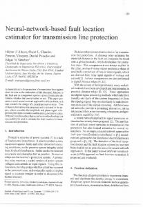
terminals. Phase angles of the sources were assumed as follows, source A: 0o, source B: –30o and source C: –15o. In Fig. 4 the fault location results for the sample fault at the line section C-T are shown. The specifications of the fault are: a-g fault, RF=10 Ω, dC=0.2 p.u.
The following assignments for the subroutine SUB_C have to be applied when utilising the approach from [8]:
(V (I
Z 1SA = (0.65 + j3.69) Ω ,
sources:
length A LB [km]) and one can determine the synchronisation operator: j A
(13c)
abs(V TBi )
| V TCi | , have to be identical (in practice very close each other).
SUB_C – synchronisation angle δA (o)
V Ai cosh(γ1A LA ) − Z c1 I Ai sinh(γ1A LA )
abs(V TAi )
If there is a fault at the section A-T (analogously is for the other sections), then the magnitudes of the phasors of voltages (for the considered i-th symmetrical component) at the tap point T, transferred analytically from the ends B: | V TBi | and C:
New fault location algorithm for three-terminal line, which utilises unsynchronised measurements of three-end currents and voltages, has been derived. The algorithm consists of three subroutines and the procedure for selecting the valid result. The distributed parameter line model is taken strictly into account for deriving the algorithm subroutines. The calculations are simple and do not involve iterative calculations, as it was the case for the previous approaches. There is a need for selecting the valid result, which is consistent with the actual fault. The selection indexes were used for that. The presented results of the ATP-EMTP evaluation prove the validity of the derived algorithm. The obtained accuracy of fault location is comparable with that achieved when using synchronised measurements.
–100 –150 –200
0
20
0.5
SUB_C – distane to fault (p.u.)
The achieved accuracy is very high. Reliable selection of the valid results was obtained as well. When implementing this method to the real device (relay, fault recorder, or stand alone fault locator), also the errors caused by non-ideal transformation of instrument transformers have to be accounted for.
o SUB_C C _( 30 ÷50 ) ms = 53.96
Fault time (ms)
40
60
d C _( 30÷50 ) ms = 0.1993 p.u.
0.4
0.3
7. References 0.2
0.1
0
0
20
Fault time (ms)
40
60
Fig. 4. The fault location example – results of the subroutine SUB_C: a) synchronisation angle δΑ, b) two solutions for the synchronisation angle δC (for the distributed parameter line model), c) unique solution for the angle δC (for the lumped line model), d) distance to fault dC
The current and voltage signals from the line end A were intentionally delayed by a single sample, while the signals from the end C by three samples. Such delays for the applied sampling frequency of 1000 Hz correspond to the case of unsynchronised measurements with the synchronisation angles equal to: δA=18o, δC=54o. The synchronisation angle δΑ (11) is determined (Fig. 4a) with very small error (0.1o). Comparing two solutions of (2) for the synchronisation angle δC (Fig. 4b) with the unique solution (3) from Fig. 4c one selects: δC=53.97o as the valid solution. Taking it, an accurate fault location is obtained (Fig. 4d). Besides the presented example, an extensive evaluation study has been performed. Different specifications of faults have been considered in the study. For example, in the synthetic evaluation for the population of 108 fault cases: • 4 fault types (a-g, a-b, a-b-g, a-b-c), faults on each of 3 sections (A-T, B-T, C-T), • • faults at 9 locations (from 0.1 to 0.9 p.u.), the maximum error in fault distance calculation does not exceed 0.2%. This is so since the distributed parameter line models were strictly taken into account for all line sections. Note: a fault resistance of 10 Ω for single phase faults and 1 Ω for interphase faults was applied.
[1] R.K. Aggarwal, D.V. Coury, A.T. Johns, A. Kalam, “A practical approach to accurate fault location on extra high voltage teed feeders”, IEEE Trans. Power Delivery, vol. 8, no. 3, pp. 874–883, Jul. 1993. [2] A.A. Girgis, D.G. Hart, W.L. Peterson, “A new fault location technique for two-and three-terminal lines”, IEEE Trans. Power Delivery, vol. 7, no. 1, pp. 98–107, Jan. 1992. [3] J. Izykowski, E. Rosolowski, R. Molag, et al., “Accurate location of faults on three-terminal line with use of threeend unsynchronised measurements”, Proc. of 16th Power Systems Computation Conf., Glasgow, 2008, CD-ROM. [4] D. A. Tziouvaras, J. Roberts, G. Benmmouyal, “New multiended fault location design for two- or three-terminal lines”, Proc. of 7th Int. IEE Conf. on Developments in Power System Protection, pp. 395–398, Apr. 2001. [5] Y. Lin, C. Liu, C. Yu, “A new fault locator for threeterminal transmission lines using two-terminal synchronized voltage and current phasors”, IEEE Trans. Power Delivery, vol. 7, no.3, pp. 452–459, Jul. 2002. [6] S.M. Brahma, “Fault Location scheme for a multi-terminal transmission line using synchronized voltage measurements”, IEEE Trans. on Power Delivery, vol. 20, no. 2, pp. 1325–1331, Apr. 2005. [7] J. Izykowski, E. Rosolowski, M.M. Saha, et al., “A fault location method for application with current differential relays of three-terminal lines”, IEEE Trans. on Power Delivery, vol. 22, no. 4, pp. 2099–2107, Oct. 2007. [8] E. Rosolowski, J. Izykowski, M. M. Saha, et al., “Accurate transmission line fault location using two-terminal measurement data without time synchronisation” Przeglad Elektrotechniczny (Electrical Review), no. 6/2009, pp. 170– 174, Jun. 2009. [9] H.W. Dommel, Electro-Magnetic Transients Program, BPA, Portland, USA, 1986.