Journal of Biomechanics 31 (1998) 161—164
Technical Note
An algorithm for determining gravity line location from posturographic recordings Vladimir M. Zatsiorsky*, Deborah L. King The Biomechanics Laboratory, Department of Kinesiology, The Pennsylvania State University, University Park, PA 16802, U.S.A. Received in final form 27 October 1997
Abstract In posturographic recordings, the center of pressure (COP) displacement does not accurately reflect migration of the gravity line (GL), the vertical line passing through the body’s center of gravity, COG. Since the horizontal ground reaction force, F , is x proportional to the horizontal acceleration of the COG its second integral does represent the horizontal position of the gravity line (GLP). However, the initial constants of integration, initial velocity and position, are not known. In this note, a technique for estimating these integration constants is suggested: zero-point-to-zero-point integration. This method is based on a postulation that when F "0, the GLP and COP coincide. By integrating F from one zero point to another zero point, both the instantaneous GLP x x and its velocity are determined. A validation of the suggested algorithm was performed using optical methods to determine the GLP during a one legged standing tasks. Cross-correlation values of GLP determined via videography and the suggested algorithm ranged from 0.79 to 0.96. These results suggest that the zero-point-to-zero-point-integration is an acceptable technique for determining GLP from posturographic recordings. ( 1998 Elsevier Science Ltd. All rights reserved. Keywords: Posturography; Stabilography; Center of pressure; Center of gravity; Gravity line
1. Introduction Displacement of the center of pressure (COP) for a standing person does not directly represent the displacement of the horizontal position of the gravity line (GLP). The gravity line (GL) is the vertical line passing through the center of gravity (COG) of the body (Gurfinkel, 1973; Eng and Winter, 1993). Technically, GLP and COP are identical only in pure static situations (Thomas and Whitney, 1959). Benda et al. (1994) estimated GLP migration by filtering COP time-history data. This method does not accommodate phase differences between the GLP and COP time histories and can only be applied with low frequencies of body swaying. Furthermore, the outcome of this method depends on arbitrarily selected filter cutoff frequencies. Levin and Mizrahi (1996) developed a method for the estimation of CLP trajectory in the frontal plane from two force
* Corresponding author. Tel.: (814) 865 3445; fax: (814) 865 2440; e-mail:
[email protected] 0021-9290/98/$19.00 ( 1998 Elsevier Science Ltd. All rights reserved. PII S0021-9290(97)00116-4
platforms. Shimba (1984) proposed using the horizontal ground reaction force, F , to estimate GLP migration. x The horizontal force is proportional to the horizontal acceleration of the COG and its second integral is proportional to GL displacement. Shimba (1984) estimated the initial integration constants through a linear curve fit of two functions, E(t) and S(t). The function E(t) is defined as E(t)"x #z F /F , 1 G 0x 0z where x is the x-coordinate of the point of application 1 of the ground reaction force, z is the vertical component G of the position vector of the COG, and F and F 0x 0z are the horizontal and vertical components of the ground reaction force. The function S(t) is the second integral of the horizontal ground reaction force. This method utilizes both the vertical and horizontal ground reaction forces and requires knowing the vertical position of the COG. A method to estimate the initial constants of integration, which makes no assumptions regarding the vertical position of the COG is suggested here.
162
V.M. Zatsiorsky, D.L. King / Journal of Biomechanics 31 (1998) 161–164
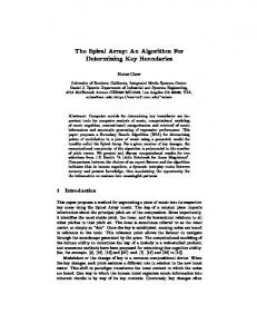
2. Zero-point-to-zero-point integration This method is based on the postulation that the GLP and COP coincide when F is zero. At this instant the x torque about A, the intersection between the vertical axis through the ankle joints and the supporting surface, is either zero or negligible (Appendix). Step 1: Determine the COP at the instant when the horizontal ground reaction force is zero, x (t ) D F "0, #01 0 x Fig. 1. Use x (t ) D !d(F (d as the first constant of #01 0 x integration—initial position; where x is the COP loca#01 tion along the x-axis, and D stands for ‘under the condition that’. With digital computers F is rarely exactly zero. x A threshold range, $d, around zero was used to determine F "0. Alternatively, zero-crossings can be deterx mined by searching for points where the horizontal force curve switches from negative to positive values. Step 2: Calculate the second integral of x¨ (t)"F (t)/m. x Start integrating at t D !d(F (d and ending at 0 x t D!d(F (d. Use xR (t )"0 as a temporary estimate 1 x 0 of the second constant of integration—initial velocity; where x¨ (t) is the horizontal acceleration of the COG, and m is the mass of the body. Step 3: Subtract x (t ) D !d(F (d from x(t ) D #01 1 x 1 !d(F (d. The difference, divided by *t"t !t , x 1 0 equals the difference between the actual and arbitrary values of initial velocity. This latter difference is equal to the actual initial velocity xR (t ); where x (t ) is the 0 #01 1 experimentally recorded value of COP, and x(t ) from 1 the calculated GLP value from Step 2. Step 4: Repeat Step 2 using the real value of the initial velocity integration constant, xR (t ). 0
Fig. 1. Estimating the integration constants by the zero-point-to-zeropoint integration. The integration of x¨ (t)"F (t)/m with a temporary x integration constant xR (t )"0 starts at time t D!d(F (d and goes 0 0 x to time t D!d(F (d. Then the actual initial velocity, xR (t ), is 1 x 0 estimated. To find the GLP path from point 0 to point 1, the horizontal acceleration, x¨ (t)"F (t)/m, is re-integrated with the actual xR (t ) as the x 0 integration constant. The same procedure continues from a zero point to the following zero-point.
Step 5: Continue the same procedure, integrating from t D !d(F (d to t D !d(F (d for the entire n x n`1 x curve. Using the symbols defined above, the horizontal position of the gravity can be expressed with the following equation:
C PP
x (t)" GLP
t
n`1
D!d(F (d x
t D!d(F (d n x
D
x¨ (t) #xR (t ) ) t#x (t ). n COP n
3. Examples and discussion The suggested algorithm was validated using videography to determine the horizontal migration of the wholebody center of mass (COM). Since migration of the COM during quiet bipedal stance does not exceed several millimeters, a value too small to be determined accurately with optical methods (Kingma et al., 1995), a one-legged standing task was investigated. During one legged standing gravity line displacements are on the order of magnitude of centimeters, and thus can be determined via typical optical procedures. Five subjects gave their informed consent to participate in this study. Subject characteristics are provided in the table. The subjects were instructed to stand on their preferred leg for 45 s with their eyes closed. The subjects stood with their hands on their hips with no specific directions given concerning the position of the non-supporting leg. A force platform operating at 30 samples per second was used to record the ground reaction forces (GRF). Thirty seconds of data, starting 10 s into the 45 s trial, were analyzed for the validation procedure. The horizontal displacement of the gravity line was calculated using the zero-point-to-zero-point algorithm. This measure of the GLP was called the GLPz, and was defined as the horizontal displacement of the GL as calculated from the zero-point-to-zero-point integration algorithm. A video camera operating at 30 frames per second (Panasonic AG450, Matsushita Electric Corporation, Secaucus, NJ) was positioned to record the frontal plane of the subjects during the one legged standing task. Retro-reflective markers were positioned on bony landmarks of the subject to define an eleven segment model of the human body: the head, neck, and trunk segment, two upper arm segments, two lower arms and hand segments, two upper leg segments, two lower leg segments, and two feet segments. A light aligned with the optical axis of the camera illuminated the retro-reflective markers. These video data were then automatically digitized with a Peak5 motion analysis system (Peak Performance Technologies, Englewood, CO). Segment mass characteristics from Zatsiorsky and Seluyanov (1983) were utilized
V.M. Zatsiorsky, D.L. King / Journal of Biomechanics 31 (1998) 161–164
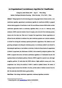
to determine the location of individual segment center of masses along with individual segment masses. From these data whole body COM was calculated using segment endpoint locations determined from the video analysis. This measure of the GLP was called the GLPv, and was defined as the horizontal displacement of the GL as determined through videography and segment mass procedures. Root mean square (RMS) values of horizontal gravity line displacement as calculated for the zero-point-tozero-point algorithm (GLPz) were compared with RMS values of horizontal gravity line displacement as determined from the video recordings (GLPv). Additionally, cross-correlation analyses were performed between GLPz and GLPv. Fig. 2 contains representative data of the GLPz and GLPv results from one subject. Notice that the GLPz and GLPv are of the same magnitude and follow the same phase relationship. The RMS values for GLPz and GLPv averaged over all subjects were 9.3$3.0 and 9.0$4.2 mm, respectively. This difference was not statistically significant at the 0.05 level as tested with a paired t-test. The crosscorrelation values between GLPz and GLPv at zero-time-lag ranged from 0.79 to 0.96 with a median value of 0.88. Table 1 presents subject characteristics, RMS values for both GLPz and GLPv, and cross-correlation values for all subjects. Since optical methods contain a certain level of inaccuracy due to the estimation of segment mass parameters and joint axis
163
locations, perfect correlation between the two techniques should not be expected. High coefficients of correlation do, however, indicate that the zero-crossing algorithm is a valid technique for calculating GLP migration during standing tasks.
Appendix The intention of this appendix is to demonstrate that when F "0 the angular momentum about A of a standx ing person does not change, H "constant. A Consider a simple pendulum system consisting of a material particle and a massless rigid rod constrained to oscillate around point A (Fig. 3). Conditions are sought at which F "0 for small amplitudes of oscillax tion. The radial (F ) and tangential (F ) components of the 3 5 force acting at A on the rod are F "mhQ 2r#mg cos h, F "mh® r#mg sin h. 3 5 The condition for F to be zero is x F sin h"!F cos h. 3 5 Combining equations (1) and (2) yields
(1)
hQ 2 sin h"!h® cos h.
(3)
(2)
Equation (3) is valid when both sides of the equation are zero and (a) h0 "0 and h® "0 (a pure static case), (b) h"0
Fig. 2. GLP determined via the zero-crossing algorithm and optical methods for subject 1. The crosscorrelation value at zero time lag is 0.94.
Table 1 Subject characteristics, RMS of GLPz and GLPv values, and cross-correlation values for all subjects Subject
Mass (kg)
Height (m)
Age (years)
RMS of GLPz (mm)
RMS of GLPv (mm)
GLPz & GLPv cross-correlation
1 2 3 4 5
70.2 75.4 64.3 89.8 68.2
1.69 1.79 1.68 1.81 1.68
26 24 21 23 28
13.77 9.68 6.08 9.50 6.82
15.82 7.56 5.29 7.56 5.80
0.94 0.88 0.96 0.79 0.83
164
V.M. Zatsiorsky, D.L. King / Journal of Biomechanics 31 (1998) 161–164
Fig. 3. A simple pendulum system. F and F are radial and tangential 3 5 components of a pin force acting on the rod at A.
and h® "0 (the pendulum is vertical and the angular acceleration is zero), or (c) h0 "0 and h"n/2 (unrealistic for standing posture — the pendulum is in a stationary horizontal position). Otherwise, equation (3) is valid if (d) the angular velocity values are large enough to compensate for low values of sin h and (f) the rod accelerates when the inclination angle increases (the horizontal projections of the radial and tangential forces point in opposite directions). These conditions are not satisfied in upright stance: sin h is much smaller than cos h, the angular velocity of body sway is small, and the body decelerates when the inclination angle increases (King and Zatsiorsky, unpublished observation). Therefore, only cases (a) and (b) are realistic. When the horizontal force is zero the angular acceleration of the simple pendulum, as well as HQ , are zero. A For a multi-link system, the time rate of the change of the angular momentum of the system, which is numerically equal to the torque about A, can be represented as the sum HQ "+ I h® #+ (r ]m a )"HQ #(r]ma) (4) A l l l l l where the subscript l refers to individual body segments, r is the vector from the origin A to the corresponding COG, and a is acceleration of the COG. Symbols without subscripts refer to the whole body and its COG. Eq. (4) states that the time rate of the change of the angular momentum about point A is equal to the sum of the time rate of change of the angular momentum about the COG (‘local’ term) plus the time rate of change of the angular momentum due to the acceleration of the COG (‘remote’ term). The remote term represents an imaginary system, similar to the simple pendulum analyzed above, with mass m located at r and acceleration a. When the system is either at rest or r is oriented vertically with zero angular acceleration, the remote term does not produce a horizontal reaction force at A. However, the magnitude of r is not fixed. In an abstract system, the tip of r can move
with a constant horizontal velocity maintaining F "0. x For upright posture this is highly improbable, since pendular movement is subjected to acceleration due to gravity. Regarding the local term of HQ , the system is anchored A at point A and cannot rotate independently around the two poles, COG and A, at the same time. For instance, when the COG is at rest (F "0) the system as a whole x cannot rotate around A. In an abstract sense F can be x zero when the external torque is not zero. If a person wind-mills his or her arms perfectly out of phase, the accelerations of the arms, radial and tangential, are equal in magnitude and opposite in direction, canceling the inertial forces. In this case, the COG resultant ground reaction force would not change, though the external torque applied to the feet and the local term of the angular momentum would change. It is unlikely that this phenomena happens during quiet standing. Thus, when the horizontal force is zero, the angular momentum of the human body does not change (fundamentally) and the COP and GLP momentarily coincide.
References Benda, B.J., Riley, P.O., Krebs, D.E., 1994. Biomechanical relationship between the center of gravity and center of pressure during standing. IEEE Transactions on Rehabiliation Engineering 2, 3—10. Eng, J.J., Winter, D.A., 1993. Estimations of the horizontal displacement of the total body centre of mass: considerations during standing activities. Gait and Posture 1, 141—144. Gurfinkel, E.V., 1973. Physical foundations of stabilography. Agressologie 20C, 9—14. Gurfinkel, V.S., Kots, Ya.M., Schick, M.A., 1965. Control of human body posture. Nauka Publishers, Moscow (in Russian). Kapteyn, T.S., 1979. Afterthought about the physics and mechanics of postural sway. Agressologie 14, 27—35. Kingma, I., Toussaint, H.M., Commissaris, D., Hoozemans, M., Ober, M.J., 1995. Optimizing the determination of the body center of mass. Journal of Biomechanics 28, 1137—1142. Levin, O., Mizrahi, J., 1996. An iterative procedure for estimation of the trajectory of center of pressure from bilateral reactive force measurements in standing sway. Gait and Posture 4, 89—99. Massen, C.H., Kodde, L.A., 1979. Model for the description of left-right stabilograms. Agressologie 20, 107—108. Shimba, T., 1984. An estimation of center of gravity from force platform data. Journal of Biomechanics 17, 53—60. Spaepen, A.J., Preeraer, L., Willems, E.J., 1979a. Center of gravity and center of pressure in stabilometric studies: A comparison with film analysis. Agressologie 20, 115—116. Spaepen, A.J., Portuin, J.M. Willems, E.J., 1979b. Comparison of the movements of the center of gravity and of the center of pressure in stabilometric studies. Comparison with Fourier analysis. Agressologie 20, 117—118. Thomas, D.P., Whitney, R.J., 1959. Postural movements during normal standing in man. Journal of Anatomy 93, 524—539. van de Morel, P.J., Massen, C.H., Kodde, L.A., 1979. Stabilograms and horizontal forces. Agressologie 20, 105—106. Zatsiorsky, V.M., Seluyanov, V., 1983. The mass and inertia characteristics of the main segments of the human body. In: Matsui, H., Kobayashi, K. (Eds.), Biomechanics VIII-B. Human Kinetics Publishers, Champaign, IL, pp. 1152—1159.