In the following we give only a brief overview of the basic steps .... Returned is a list containing pointers to all of these lists, which represents the whole left. (or right) .... the tolerance boundary in account: the left endpoint is either the tangent point ..... since the number of gates is n-2, additional temporary gates for the start.
ACS Algorithms for Complex Shapes with Certified Numerics and Topology
CGAL-based implementation for the approximation of polygonal curves with a minimum number of biarcs
G¨ unter Rote
Astrid Sturm
ACS Technical Report No.: ACS-TR-2434-02 Part of deliverable: Site: Month:
WP-II/D5 FUB 36
Project co-funded by the European Commission within FP6 (2002–2006) under contract nr. IST-006413
p2 p7 p5 p3
p1
ε
p6 p8
p4
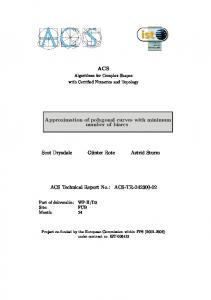
Figure 1: Polygonal tolerance region R with gates Abstract We present a C++ open source implementation of an algorithm for the approximation of open polygonal curves with a minimum number of biarcs. The implementation is based on CGAL and in particular on the CGAL 2D curved kernel. To our knowledge this is the first implementation computing the minimum number of biarcs. Conventional biarc algorithms (also used in industry) operate on discrete sets of points (and tangent vectors), by fitting biarcs between selected pairs of points. These methods are based on heuristics and do not give any guarantees regarding the number of on biarcs needed for the approximation. Our algorithm computes the point pairs which lead to an approximation with the minimum number of biarcs.
1
Introduction
In this technical report we present an implementation for an algorithm for tangent-continuous approximation of an open polygonal curve with minimum number of biarcs, answering the min-# for biarcs. The theoretical foundations of the algorithm are given in the technical report ACS-TR-2434-01 of year two or in the paper [5]. In the following we give only a brief overview of the basic steps of the algorithm and will later focus on the implementation of these. Although the biarc approach is theoretically very straight forward, the implementation proved itself challenging due to the many involved geometrical details. We assume that the problem is given in the form of a tolerance region around the given curve, which is split into subregions by gates through the given points, see Figure 1. The precise formulation is given below. We now assume that an oriented tangent direction ti is specified for each vertex pi of the open polygonal curve. Our algorithm will select a subsequence of the input points and interpolate between them smoothly by biarcs, pieces consisting of pairs of circular arcs, respecting the tangent directions ti at the points which are used. Our algorithm will find such an approximation with the minimum number of biarcs given a set of gates and a tolerance region. In this setting the gates would ideally be perpendicular to the tangent directions ti , but we do not require this. 1
p1 c1
c2 p2
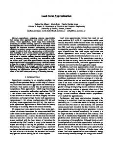
Figure 2: The joint circle, and an S-shaped biarc with both tangents pointing outside the joint circle We require that the input satisfies the following assumptions: (A0 ) R is a simple polygon passing through all gate endpoints; (B0 ) R does not intersect the polygon or the interiors of the gates. (C0 ) Each tangent ti passes through gate gi in the same direction as the original polygonal chain P ; that is, from the side of the gate on which pi−1 pi lies to the side on which pi pi+1 lies. From the implementation point of view, we provide routines constructing the gates and the boundary in a very simple manner, if the user doesn’t provide them. We first find all valid biarcs and then build the directed graph of these biarcs from the start point to the end point of the polygonal curve. The last step is the computation of the shortest path. The code of the implemented classes and functions is available at http://www.inf.fuberlin.de/groups/ag-ti/index.php?id=90.
2
Implementation
The code is based on CGAL and uses the generic CGAL kernels. As one of the major geometric ingredients of the algorithm are the biarcs, the implementation intensively uses the CGAL 2D circular kernel in addition to a basic kernel. Circular_kernel_2 extends the Kernel concept.The circular kernel introduces a new point representation, points with coordinates that are algebraic numbers: CircularArcPoint_2. Circular arcs have endpoints that are CircularArcPoint_2, and they are supported by a Circle_2 whose center is a Point_2. Therefore we deal in the implementation with two types of points, once CircularArcPoint_2 for the intersection computations regarding circles and with regular CGAL Point_2 for all other geometric settings. The programing interface for our algorithm is the function biarc_approximation. To be as general as possible, the function deals with templates to define the input and the output data storing structures. 2
template void biarc_approximation (Pointlist* pointlist, InputIterator tangent_start, InputIterator tangent_end, Boundarylist* left_boundary, Boundarylist* right_boundary, Gatelist* gate_list, Pointlist* biarc_vertices, OutputList* joint_points, Kernel CGAL_Kernel) The parameters are defined as follows: • pointlist of type Pointlist* is a pointer to the container storing the input points of the original polygonal curve. • tangent_start and tangent_end of type InputIterator are iterators pointing to the first and last element in the data structure storing the tangent directions of the original polygonal curve. • left_boundary and right_boundary of type Boundarylist* are pointers to the container storing the left and right boundary part of R, the tolerance region. • gate_list of type Gatelist* is a pointer to the container storing the gates of the tolerance region. • biarc_vertices of type Pointlist* is a pointer to a container which will store the resulting vertices, which define the minimum number of biarcs. • joint_points of type OutputList* is a pointer to a container which will store the source and target of the joint circle arcs belonging to the biarcs of the solution. • Kernel of type Kernel specifies the geometric standard kernel used, e.g. Cartesian We first pair each input point with its tangent, then we precompute the visibility regions(the exact construction is explained in section visibility region). Using the precomputed information we iterate through all point pairs of input points and compute the the valid joint arc, if it exists. If we find a valid joint arc, we connect the two points with an edge in the graph and also store the source and target of the joint arc with the edge. Once we checked all point pairs for the existence of valid biarcs between them, we construct the shortest path in the graph. Because we stored also the source and target of the valid joint arcs, the function not only returns the vertices of the polygonal curve which lead to the approximation with a minimum of biarcs, but also gives the user 3
the possibility to choose from all possible valid biarcs for each point pair of the solution, the one which suits his setting best. In the next subsections the several steps of the implementation are explained in detail.
2.1
Gates and boundary
The construction of a appropriate tolerance region with gates is a problem of its own, which we don’t really treat. We do provide simple routines to construct gates and the a simple version of a boundary. Ideally the tolerance region with gates is provided by the user. The concept for the gate construction is based on the gate_2 class which is defined as follows: Definition: An object g of the data type gate_2 is a directed straight line segment in the two-dimensional Euclidean plane 2, it inherits from Segment_2. Creations: • gate_2 (const Point_2& point,const double length, const Segment_2& lsegment, const Segment_2& rsegment) Constructs a gate from the original point, total length and the bisector of the angle between the segments (usually the target point of the lsegment and the source point of the rsegment correspond to the original point). • gate_2 (const Point_2& point, const Point_2& lpoint, const Point& rpoint) Constructs a gate from the left and right endpoints of the gate. Operations: • Point_2 lendpoint () const Returns the gate’s left endpoint (the endpoint on the left boundary chain). • Point_2 rendpoint () const Returns the gate’s right endpoint. • Point_2 center () const Returns the gate’s center/ the original point. The user can define his one gate class, but has to provide the same operations and functionality as the gate_2 class. For the gate construction we supply only this simple function which constructs each gate as a segment of length twice epsilon centered on an original point and on the bisector of the angle between the pre and successor segments of the original point. template void construct_gate (InputIterator first, InputIterator past,Gatelistpointer gates, Kernel param, double epsilon) first and past are InputIterators of the container which stores the original polygon. gates is a pointer to a container which will store the constructed gates. If the user constructs his own gates, he only needs to provide a container 4
with all standard operations, as for the std::vector container, which stores the gates in the order they occur when traversing the original curve from the starting to the end point. The concept for the boundary: The boundary is represented site and block wise. A boundary block is the part of the boundary between two gates. We require that the left part and the right part of the tolerance boundary are stored separately. The polygonal curve defining one site of the boundary is represented with a container which elements are pointers to containers storing the boundary segments of a block,e.g. the whole left boundary is stored in a primary container whose first element points to a container storing the segments of the left first block, the second element of the primary container points to a container storing the segments of the left second block and so one. The right boundary is stored in the same way. We require that the containers provide forward and backward iterators and supply all standard operations of a std::vector container. The function we provide to build the boundary is std::vector generateBasicBoundsFromGates (const which_edge& we, const gatePointerList& gatepointers, const std::list& Polygon, const double& eps) The parameters are defined as follows: • we of enum type const which_edge& is a constant to distinguish between the left and right boundary. • gatepointers of type gatePointerList& is a container storing pointers to the gates. • Polygon of type const std::list& is the list of the original input points. • eps of type const double& is the approximation tolerance, which also defines the width of the gates. The function handles the creation of basic boundary segment lists from gate pointers and given start and end points. The segments between two gate endpoints are put into segment lists, in this simple case, each of these lists contains exactly one segment between two successive boundary endpoints. Returned is a list containing pointers to all of these lists, which represents the whole left (or right) boundary.
2.2
Visibility region
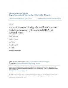
For each possible starting point pi of a biarc, the tangent direction ti is fixed. The pencil of circular arcs starting in this direction forms a circular visibility region Wi inside the feasible region R, see Fig. 3. The arcs forming Wi terminate when they reach gi ; since we want to construct valid biarcs, we are not interested in arcs that intersect gi a second time. To find a valid biarc that starts at pi and ends at pj we need to reach a point on the joint circle J via a valid arc from pi and then continue via a valid 5
pi
ti
Figure 3: A circular visibility region Wi arc to pj . The possible joints from the perspective of pi are the intersection of J and the circular visibility region of pi . By reversing the direction of the second arc and tangent we can compute the second arc in the same way. We will use arc a ˜2 , which has opposite orientation and whose tangent at pj is t˜j , ˜ j . Our goal is to the reverse of tj . We will call this circular visibility region W ˜ j. find all points on J which are in both circular visibility regions Wi and W As a first step in this process we determine the portion of each gate that is ˜ j for each within Wi for each point pi and the portion of each gate that is in W point pj . The portion of a gate that is visible in Wi consists of at most three intervals: one interval where the gate is reachable in the forward direction, and two segments where the gate is reachable in the backward direction by clockwise and counter-clockwise arcs, respectively. These intervals may be adjacent and can be stored in O(n2 ) space. The concept for the visibility region is based on the class visibility_region_2 which is defined as follows: Definition: An object v of the data type visibility_region_2 stores the visibility region of a given point (with fixed tangent direction). In particular the object v stores the vertex which is the starting point of the visibility region and in in three containers the segments resulting the intersection of the visibility region with the gates traversed in order. We use three containers, to distinguish between the three intersection intervals explained above. Additional we store in two containers for each traversed gate the tangential point of the pencil of arcs with the gate in CW and CCW orientation (if they exist). To find the tangential point we construct the circle which belongs to the pencil of circular arcs and also is tangent to line defining the gate. The function we use is construct_circle which is explained later on. Operations: • Point_2 vertex () const Returns the starting point of the visibility region. • Pointlist* l_gate_tangents () const Returns the pointer to the CCW tangent point list. • Pointlist* r_gate_tangents () const Returns the pointer to the CW 6
tangent point list. • Segmentlist* fsegit () const Returns the pointer to the forward segment list. • Segmentlist* back_left_segit () const Returns the pointer to the CCW back segment list. • Segmentlist* back_right_segit () const Returns the pointer to the CW back segment list. The function which constructs the visibility region is template void compute_visibility_region( Polygon& polygon, Boundary& left_boundary, Boundary& right_boundary,Gate& gate_list, VisRegion& visregion, Kernel CGAL_kernel) . The parameters are defined as follows: • Polygon& polygon is the container storing the polygon, the polygon elements are data pairs composed of the input points and their tangents. • Boundary& left_boundary and Boundary& right_boundary are the two boundary storing containers. • Gate& gate_list is the gate storing container. • VisRegion& visregion is a storing container for the visibility regions computed in this function. • Kernel CGAL_kernel is the CGAL-Kernel defined by the user. The elements of the result list (visregion) are pointers to visibility region objects. Each visibility region object stores the visibility region of one point of the original point set. We iterate through all elements of the polygon list and construct the visibility region for each data pair, therefore the elements of the returned list are in the same order as the input points are traversed. We constructed the forward segment at each gate by separately constructing the left and the right endpoint of the segment. For the construction we have to distinguish if the tangent of the current data pair still reaches the gate, or if the pencil of circular arcs consists only of CW or CCW arcs. First we explain the construction of the forward segment for the case that the tangent reaches the gate, so we deal with CW and CCW arcs. The left endpoint is defined by the smallest circular arc of the CCW circles of the pencil of arcs which still reaches the gate and does not intersect the left boundary of the tolerance region. With the smallest circular arc we refer to the one with the smallest radius. The right endpoint is defined the same way for CW circular arcs, therefore only the construction of the left endpoint of the forward segment is explained in details. 7
l bisector 2
x s
bisector 1
Figure 4: Construction of the CW and CCW tangent circle. Only for the CW circles the tangent point on l also lies on s. Therefore in this cases the CCW circles don’t have a tangent point on the segment s. Looking at the starting point and the first gate the pencil of arcs intersects, there are two possibility for the left forwards segment endpoint without taking the tolerance boundary in account: the left endpoint is either the tangent point or the left end point of the gate segment. First we compute a circle which fulfills the condition to belong to the pencil of circular arcs of the current starting point and that is tangent to the line supporting the gate. We use the function template Circle_2* construct_circle (Point_2 x,Line_2 l,Segment_2 s, bool right_of_tangent, bool right_of_segment) to construct this circle. The first two parameters are the starting point and the tangent defining the current pencil of arcs. The third parameter is the segment to which supporting line the circle is supposed to be also tangent. The last two parameters define which tangent circle we are looking for. The reason we need the last two parameters is, because the first three parameters define two feasible circles. This two circles are the one to the left and one right of the line l which are tangent to l in the point x and tangent to the line defined by s. For the CW circular arcs only the circle left of the line l is feasible and for the CCW only the circle right of l is feasible. Both circles are either left or right of the line defined by the segment s, therefore the function either returns a pointer to a circle which fulfills all requirements, or NULL, if the circle is on the wrong side of the segment s, see also Fig. 4. Even if the function returns a circle, it is only guaranteed to be tangent to the line defined by s, so in the next step we check if then tangent point is on s and store this information. If the tangent point exists the constructed circle c1 is the circle from the pencil of circular arcs with the smallest radius still reaching the gate gi . If the tangent point does not exist the circle c1 is the the circle defined by the current data pair and the left endpoint of the gate. The intersection point of c1 with the gate is the left endpoint of the forward 8
p_6
lc g_i+1 g_i
Figure 5: Construction of the CCW forward visibility segment. The point p6 is outside the current circle c1 but above the line lc, therefore the CCW circular arc on c1 from gi to gi + 1 is a valid circular arc. segment if the circular arc c1 does not intersect the left boundary. Therefor we walk along the left boundary of the current boundary block and check for each endpoint of the left boundary segments if it is inside the circle c1 . If all segment endpoints are inside the circle, the arc on c1 from the starting point to the intersection point on the gate is valid. If a target point of a boundary segment s is outside we still have to check if it is also below the circular arc, because we need only to check if the circular arc intersects the boundary and not the whole circle. We use the line lc defined by the source and target of the current circular arc, to distinguish between above and below the arc, see also Fig. 5. If a target point of a boundary segment s is below the arc, the target point redefines c1 as the circle though this point. At last if the current gate gi is not the first gate intersected by the pencil of circular arcs, we need to check if the circular arc c1 is inside the current visibility region, that was defined by the boundary block ahead. Therefore we intersect c1 with the gate gi−1 and check if the intersection point is inside the forward segment on gate gi−1 , if not the left endpoint of the forward segment on gate gi−1 defines the new circle c1 . The intersection of c1 with the gate gi is the left endpoint of the forward segment of gate gi . The construction of the right endpoint is symmetric. If the pencil of circular arcs reaching a gate consists only of CCW arcs the right endpoint of the forward segment is constructed by walking along the right tolerance boundary and constructing the CCW circle with the biggest radius not intersecting the boundary. Here we need to construct for every segment of the boundary the tangent point with the pencil of circular arcs if it exists. We do the construction in the same manner as for the tangent points at the gates. To find the CCW circle with the biggest radius not intersecting the boundary, we construct the circle c2 as the circle tangent to the first segment of the boundary block or if the tangent point doesn’t exist, c2 is the circle 9
through the target point of the first boundary segment. Now we walk along the boundary and check for each segment if the tangent point (or the segment target if the tangent point does not exist) is inside the circle, if it is, the tangent point/segment target defines the new circle c2 . We do a symmetric construction for the case that only CCW arc are left. The construction of the back segments depends on the forward segment,e.g. the circle c1 that defines the left endpoint of the forward segment also defines the right endpoint of the left back segment. If c1 is the tangent circle or it intersects the gate a second time there could exist a left back visibility segment, if not there is no back visibility for the current boundary block. If a back visibility exists we construct the missing segment endpoint by again walking along the boundary like in described for CCW arcs above. Different than in the forward move the final backward arc on gate gi depends on the backward pencil coming back from the gate gi+1 . We proceed iterative boundary block wise for each point pair till either the last gate is reached or an intermediate gate is not reached.
2.3
Joint computation
The locus of possible joints forms a circle J that passes through pi and pj [1, 3, 4], see Figure 6. For each point on this joint circle J, there is a unique biarc which uses this point as the joint. There are some degenerate cases: as a limiting case, the joint could be one of the points pi or pj : the joint circle might be a line; if there is a circle through pi and pj with the given tangents, this is the joint circle, but all joints on this circle lead essentially to the same biarc. Proposition 2.1. One circular arc of the biarc lies outside the joint circle J, and the other lies inside J, except for their endpoints, which lie on J. Both tangents ti and tj point to the same side (either inside or outside) of J, and they form equal angles with J. (In fact, the last property characterizes the joint circle.) The construction of the joint circle is done in the function template Object construct_joint_circle (Point_2 x, Point_2 y, Line_2 lx, Line_2 ly) The parameters are the two data pairs, x and lx correspond to pi with ti , and y, ly to pj , tj . We first construct the circle which is defined through the point triple x, y and the intersection point of the two tangents lx, ly. This circle c is the locus of all centers of circles which form equal angles with lx, ly. Next we intersect c with the bisector of the segment xy. The two intersection points correspond to two possible centers for the joint circle, but only one of this centers is feasible. Looking at the two tangents lx, ly, only one of the two intersection points is on the same side of the two tangent lines lx and ly. This point is the center of the joint circle, see also Fig. 6.
10
H
lx
I1
x y xy I2
bisector of xy
ly
Figure 6: Construction of the joint circle defined through the two data pairs x, lx and y, ly. The intersection point I1 is to the right of lx and to the right of ly and therefore the center of the joint circle. The circle with the second intersection point as center forms only equal angles with the tangent lines if the orientation of one of the tangents is flipped. Therefore the construction of the joint circle can be geometrically done with a few simple routines: first the construction of a circle through a point tripel , then construction of the bisector of a segment, next the intersection of this circle and bisector,last we only need to check which intersection point lies on the same side of two lines. Once the joint circle is constructed we can check for each forward segment if the circle already entered the visibility region, did not enter it jet, or left it already. We do this by binary search on the forward segments of the gates. We don’t need to compute the intersection of the joint circle with the specific gate, it suffices to check for the positions of the endpoints of the forward segment regarding the joint circle, e.g. if one endpoint is inside the circle and the other outside we know that the joint circle is inside the visibility region. The binary search for the last gate the joint circle intersects inside the forward visibility segment is done with the function: template gate_2* do_binary_search (Point_2 x,Line_2 lx, visibility_region_2 x_visibility,InputIterator first_gate, InputIterator last_gate, int num_of_visible_gates, Circle_2 jointcircle, int& gatepos,bool out,) The parameters are defined as follows: • Point_2 x is the starting point of the visibility region. • Line_2 lx is the tangent at the starting point x. 11
• visibility_region_2 x_visibility is the visibility object storing the visibility region of x. • InputIterator first_gate and InputIterator last_gate are interators pointing to the first and last gate of the tolerance region reached by the visibility region of x. • int num_of_visible_gates is the number of gates crossed by the visibility region of x. • Circle_2 jointcircle is the joint circle. • int& gatepos stores the position of the gate within the gates storing container. It stores the position of the gate that is also returned by the function. This is the last gate the joint circle intersects inside the forward visibility segment. • bool out tells if the tangent line lx is inside or outside of the jointcircle. The construction of the joint interval, the part of the joint circle that is inside the tolerance region and is visible from the points which are suppose to be the starting and endpoint of a possible biarc, is done with the function: template Object* construct_joint_arc (Point_2 x, Point_2 y, Line_2 lx, line_2 ly,visibility_region_2 x_visibility, visibility_region_2 y_visibility, InputIterator left_boudnary,InputIterator right_boundary,InputIterator first_gate, InputIterator last_gate, int num_of_intermediate_gates, Kernel CGAL_kernel) The function returns a pointer to a CGAL object, because the joint interval constructed can be any of the following: a circular arc, a segment, a point, or NULL if no feasible joint interval exists. The other parameters are defined as follows: • Point_2 x and Point_2 y are the starting and endpoint of the biarc we are looking for. • Line_2 lx and Line_2 ly are the tangents in x and y. • visibility_region_2 x_visibility and visibility_region_2 y_visibility are the visibility objects storing the visibility region of x and y. • InputIterator left_boundary and InputIterator right_boundary are Iterators pointing to the containers storing the left and right side of the tolerance boundary.
12
• InputIterator first_gate and InputIterator last_gate are Iterators pointing to the first and last gate between x and y. •
int num_of_intermediate_gates is the number of gates between x and y.
To construct the joint interval we need to do several case distinction, depending on if the joint circle is a circle or a segment, and also we need to distinguish if the tangent are inside or outside the joint circle. The construction is straight forward like described in the technical report and uses basically the function introduced in this report. Therefore we don’t go into the details of the implementation of the joint interval.
2.4
example programm
typedef typedef typedef typedef typedef typedef typedef typedef typedef typedef typedef typedef
Cartesian Algebraic_kernel_for_circles_2_2 Circular_kernel_2 Point_2 Segment_2 Ray_2 gate_2 Line_2 Circular_arc_point_2 std::pair std::vector std::vector
Kernel; Algebraic_k; Circular_k; Point_2; Segment_2; Ray_2; Gate_2; Line_2; Circular_point; point_pair; boundList; gatePointerList;
int main(){ Circular_k param; // epsilon double eps(1); // create a simple test polygon Point_2 p1(0,0),p2(2.2,2.44),p3(8.04,0),p4(11.96,0.04),p5(15.92,4.04); std::list Polygon.push_back( Polygon.push_back( Polygon.push_back( Polygon.push_back( Polygon.push_back(
Polygon; p1); p2); p3); p4); p5);
assert(Polygon.size() >= 2);
13
std::list tangents; Point_2 p6(0.7859, 4.0028); Point_2 p7(6.0773, 3.6276); Point_2 p8(11.9962, -1.2519); Point_2 p9(20.717, 3.009); Point_2 p10(18.0048, 10.3984); Line_2 l1(p1,p6),l2 (p2,p7),l3 (p3,p8), l4 (p4,p9),l5 (p5,p10); tangents.push_back( l1); tangents.push_back( l2); tangents.push_back( l3); tangents.push_back( l4); tangents.push_back( l5);
///////// Demonstration of automatic gate/ boundary creation ///////// // construct the gates with total width 2*eps from polygon data std::vector gatelist; construct_gate(Polygon.begin(), Polygon.end(), &gatelist, param, 2*eps); // for each 2 gates, there is a list of boundaries between them. // since the number of gates is n-2, additional temporary gates for the start // and end points of each boundary are generated internally. std::vector leftBounds = generateBasicBoundsFromGates (LEFTSIDE, gatelist, Polygon, eps); std::vector rightBounds = generateBasicBoundsFromGates (RIGHTSIDE, gatelist, Polygon, eps); std::cout