IEEE MICROWAVE AND WIRELESS COMPONENTS LETTERS, VOL. 17, NO. 12, DECEMBER 2007
861
Active Microwave Circuit With Negative Group Delay Blaise Ravelo, André Pérennec, Marc Le Roy, and Yann G. Boucher
Abstract—In this letter, we report on the design, simulation and implementation of an active negative group delay circuit that operates at 1 GHz with a group delay and a gain, respectively, around 2 ns and 2 dB. Analytical formulas are proposed to demonstrate that the adopted topology is able to simultaneously achieve negative group delay (NGD) and gain while fulfilling active device constraints. The theoretical and simulated results are both validated by frequency measurements of a two-stage active microwave circuit. Index Terms—Active devices, negative group delay (NGD).
I. INTRODUCTION OR numerous applications, particularly in modern highspeed telecommunications, flat group delay or linear phase is necessary to avoid distortion in the baseband signals. In the microwave domain, group delay equalizers are used to compensate for group delay variations mostly introduced by filters [1] or amplifiers [2]. Time delay variations are also known to cause instabilities in feedback circuits in oscillator applications [3]. To reduce such perturbations, Lucyszyn et al. [3], [4] have put forward an original negative group delay synthesizer. This narrow band Microwave Integrated Circuit synthesizer, built with varactors, field effect transistors (FET) and lumped components, operates in reflection and needs a coupler to pass into transmission. High negative group delay (NGD) values are obtained at 1 GHz but also with high losses. Since this first proposal in microwave domain, several topologies exhibiting negative group delay have been proposed and we can merge these devices in two categories according to their operating frequency domain. The first one, essentially devoted to the microwave domain, is composed of passive left-handed media parallel resonant and high-pass – (LHM) built with networks [5]. Nevertheless, to achieve a significant NGD value, many cells have to be cascaded resulting in a very low transmission level caused by resonant absorption losses. The second category is only devoted to very low frequencies (below a few hundred kHz) and these circuits, built with operational amplifiers and lumped components [6], [7] have been mainly designed to lay down the general principles of NGD and as
F
Manuscript received April 2, 2007; revised August 29, 2007. B. Ravelo, A. Pérennec, and M. Le Roy are with the Laboratoire d’Electronique et Systèmes de Télécommunication (LEST—UMR CNRS 6165), Université de Bretagne Occidentale, Brest 29238, France (e-mail:
[email protected];
[email protected];
[email protected]). Y. G. Boucher is with the Ecole Nationale d’Ingénieurs Brest (ENIB/RESO), Brest F-29238, France. Color versions of one or more of the figures in this paper are available online at http://ieeexplore.ieee.org. Digital Object Identifier 10.1109/LMWC.2007.910489
demonstrators to illustrate higher frequency experiments. These electronic circuit approaches present gain and NGD simultaneously but can not be transposed into the microwave domain due to the component bandwidth limitations. To design a NGD circuit suitable for microwave applications, we propose, in this letter, a new active topology that produces NGD with loss compensation. To achieve these objectives while meeting active device requirements, we have tested several topologies, and for the adopted solution, we show analytically the NGD existence and present the design equations. Then, the implementation in microstrip technology of a two-stage circuit, that operates around 1 GHz, is described. Simulation and experimental frequency results are compared and discussed. II. ACTIVE DEVICE TOPOLOGY WITH NEGATIVE GROUP DELAY To compensate for the inherent losses of passive circuits with NGD, active components, such as a FET, must be associated with passive elements. But, an active device at microwave frequencies must simultaneously meet the specifications of gain, input and output return losses, noise factor in the passband, and stability at any frequencies. In this context, the notion of topology is of paramount importance. These considerations led us, first, to try to associate the wellknown NGD passive circuits [5], [8], and particularly the parallel network in cascade or in shunt with an FET. We also looked for a possible interaction between the transistor and the passive elements while keeping the target topology as simple as possible. But finally, among many investigated topologies, an network (Fig. 1) appears to be FET cascaded with a series the most suitable one to meet all the requirements. First, the FET is represented by its low frequency model, i.e., the transconduc, and the drain-source resistor, . The group delay tance, parameter phase versus anis defined by differentiating the . Then, at the resogular frequency, 1 nance frequency, (1) is the input impedance of the reference ports (50 in practice). At the resonance, the group delay is always negative and proportional to . The scattering parameters are given by (2) (3) The NGD occurs at the resonance where the parameter is minimum. As decreases, the NGD value increases and conse-
1531-1309/$25.00 © 2007 IEEE
862
IEEE MICROWAVE AND WIRELESS COMPONENTS LETTERS, VOL. 17, NO. 12, DECEMBER 2007
Fig. 1. Series RLC resonant network cascaded in shunt with an FET.
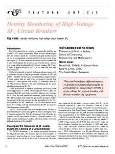
Fig. 3. Photograph of the two-stage NGD circuit with the component values. Fig. 2. Two-stage ideal circuit with bias networks in thin lines.
quently is also lowered. The group delay of the series network in shunt, on its own, can be expressed versus its quality factor, (4) For the active cell (Fig. 1), this expression is modified as (5) From (1) and (5), it becomes evident that increasing improves and thus the NGD value while narrowing the resonance band is and reducing the NGD bandwidth. Moreover, in (5), if higher than , the negative group delay value can be slightly improved in the active topology. These equations force us to and values and in that give priority to an FET with high case a compromise between low and high values may be found to achieve gain and an NGD value. These explanations may be partially summed up by the following ratio:
III. CIRCUIT IMPLEMENTATION AND EXPERIMENTAL RESULTS To validate the concept of active device with NGD, we built a circuit operating at centimetric wavelengths to avoid too many high frequency parasitic effects and to stay in the validity domain of the FET model. A two stage device ensures that all our objectives could be reached with a significant margin, i.e., at least a group delay below -2 ns, gain around 2 or 3 dB and input/output matching below 10 dB. Then, from these values and by inverting (1), (3), (7), and (8), the component values can be calculated for the specified FET. If both stages resonate at the same frequency, the total insertion losses and group delay are expressed as
(9)
(10) (6) From (3), output matching may also be obtained for a high value and a not too small value (toward ). Input matching can simply be done with a shunt resistor (Fig. 2) at the FET input. Then, the input return loss is simply expressed as (7) And at the resonance, the transmission parameter is modified as follows: (8)
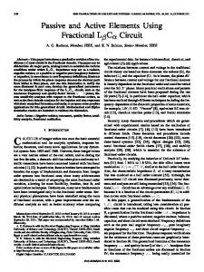
where the index 1, 2 an correspond, respectively, to the first and second stages and to the overall circuit. Finally, the electromagnetic simulation (ADS Momentum software) shows responses really close to the results obtained from our analytical low frequency model except for a slight shift in the resonance and in Figs. 2 frequency. First, we biased the circuit ( and 3) in a traditional way for both the gates and the drains. Fig. 4 compares the EM simulation results to measurements for the scattering parameters and the group delay. These results were obtained with no adjustment. One should note the good agreement between simulations and measurements, especially for the gain and the group delay values that reach respectively 1.68 dB and 2.3 ns with matching better than 10 dB. The slight
RAVELO et al.: ACTIVE MICROWAVE CIRCUIT
863
value is reached with fewer cells and the NGD bandwidth is slightly improved while meeting all the active design requireand and ments. We further biased the transistors between and through the high value inductors ( and between in Figs. 2 and 3). Under this configuration, the results of the second set of measurements were exactly the same as the networks ensure two functions and the first ones. So, the whole circuit could be simplified. IV. CONCLUSION An active circuit showing NGD and gain simultaneously is, for the first time, designed and implemented at microwave frequencies. Measurements are really close to those expected from our analytical equations and, at 1 GHz, a 2 dB gain is associated with a 2 ns group delay. This topology may also be transposed to higher frequency bands with a more complete FET modellumped components into distributed ling and by passing planar technology. Tunable capacitances and inductances could be used separately or together to control either the frequency or the level of the NGD. Moreover, stages with different resonant frequencies would produce broadband NGD suitable for ultra wideband (UWB) applications and for baseband numerical signals in inter- or intra-chip interconnects. REFERENCES
Fig. 4. (a), (b) Measured and simulated S -parameters and (c) group delay.
shift in the frequency measurements is fully explained by the and component tolerances (see Fig. 4). We obtain a better agreement compared with the passive circuits operating at a similar frequency band [5], a higher NGD
[1] H. T. Hsu, H. W. Yao, K. A. Zaki, and A. E. Atia, “Synthesis of coupled-resonators group-delay equalizers,” IEEE Trans. Microw. Theory Tech., vol. 50, no. 8, pp. 1960–1968, Aug. 2002. [2] K. Murase, R. Ishikawa, and K. Honjo, “Group delay compensation technique for UWB MMIC using composite right/left-handed circuit,” in Proc. Asia-Pacific Microw. Conf., Yokohama, Japan, 2006, pp. 1409–1412. [3] S. Lucyszyn, I. D. Robertson, and A. H. Aghvami, “Negative group delay synthesiser,” Electron. Lett., vol. 29, no. 9, pp. 798–800, Apr. 1993. [4] S. Lucyszyn and I. D. Robertson, “Analog reflection topology building blocks for adaptative microwave signal processing applications,” IEEE Trans. Microw. Theory Tech., vol. 43, no. 3, pp. 601–611, Mar. 1995. [5] O. F. Siddiqui, M. Mojahedi, and G. V. Eleftheriades, “Periodically loaded transmission line with effective negative refractive index and negative group velocity,” IEEE Trans. Antennas Propag., vol. 51, no. 10, pp. 2619–2625, Oct. 2003. [6] T. Nakanishi, K. Sugiyama, and M. Kitano, “Demonstration of negative group delays in a simple electronic circuit,” Amer. J. Phys., vol. 70, no. 11, pp. 1117–1121, 2002. [7] D. Solli and R. Y. Chiao, “Superluminal effects and negative delays in electronics, and their applications,” Phys. Rev. E, no. 5, pp. 56601. 1–056601.4, Nov. 2002. [8] V. Eleftheriades, A. K. Iyer, and P. C. Kremer, “Planar negative refractive index media using periodically L-C loaded transmission lines,” IEEE Trans. Microw. Theory Tech., vol. 50, no. 12, pp. 2702–2712, Dec. 2002.