Hindawi Publishing Corporation Discrete Dynamics in Nature and Society Volume 2013, Article ID 712486, 9 pages http://dx.doi.org/10.1155/2013/712486
Research Article Adaptive Fault-Tolerant Control for Flight Systems with Input Saturation and Model Mismatch Man Wang,1 Jianying Yang,1 and Nan Li2 1
Department of Mechanics and Aerospace Engineering, State Key Laboratory for Turbulence and Complex Systems, College of Engineering, Peking University, Beijing 100871, China 2 School of Automation, Chongqing University, Chongqing 400044, China Correspondence should be addressed to Jianying Yang;
[email protected] Received 1 August 2013; Accepted 12 August 2013 Academic Editor: Guanghui Wen Copyright © 2013 Man Wang et al. This is an open access article distributed under the Creative Commons Attribution License, which permits unrestricted use, distribution, and reproduction in any medium, provided the original work is properly cited. A novel scheme for fault-tolerant control is proposed in this paper, in which model reference adaptive control method is incorporated with control allocation to cope with simultaneous actuator failures, input saturation, and model mismatch in the flight system. In order to reduce performance degradation caused by actuator failures, the proposed scheme redistributes the control signal to healthy actuators and updates the weighting matrix based on actuator effectiveness. Because of saturation errors resulting from actuator constraints and model mismatch caused by abnormal changes in the system, the original reference model may not be appropriate. Under this circumstance, an adaptive reference model which can also provide satisfactory performance is designed. Simulations of a flight control example are given to illustrate the effectiveness of the proposed scheme.
1. Introduction Actuator failures may adversely affect the stability and performance of flight systems. Fault-tolerant control (FTC) has been studied as a method for accommodating failures. In the past decades, a number of approaches have been proposed for FTC, including sliding mode control-based designs [1, 2], variable structure control-based designs [3], learning-based approaches [4], and adaptive control-based designs [5]. The availability of actuator redundancy is an important element of FTC. Control allocation (CA) is an approach that can effectively manage redundancy by distributing virtual control law requirements to redundant actuators in the most efficient manner [6]. There is an extensive literature on CA approaches and applications. Enns presented the linear and quadratic programming approaches in detail in [7]. H¨arkeg˚ard and Glad compared control allocation with optimal control for solving actuator redundancy in [8]. Several CA approaches taking into account actuator limits have been discussed [9–11]. Kishore et al. gave an algorithm that updated the weighting matrix to deal with actuator limits
in [9]. However, in the event of failure, only depending on updating the weighting matrix sometimes may be invalid. In addition, flight systems may experience other disruptive factors such as model mismatch. Model mismatch can be caused by icing or damage to the aircraft. Joshi et al. first considered this problem in [12] and further developed his work in [13]. Although the previous work has achieved satisfactory tracking performance, none of them considered actuator limits. In this paper, we develop a novel scheme combining CA with model reference adaptive control (MRAC) for flight systems with simultaneous actuator failures, model mismatch, and input saturation. On the basis of the existing literature, this paper proposes an improved control allocation (ICA) method that updates the weighting matrix based on actuator effectiveness. In addition to updating the weighting matrix, this paper employs the positive 𝜇-modification method [14] to impose constraints on actuators. MRAC can guarantee the closed-loop stability of the system and reduce the error caused by actuator failures. Because of input saturation and model mismatch, the original reference model may not
2
Discrete Dynamics in Nature and Society
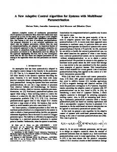
be appropriate. We have designed an adaptive reference model that can provide satisfactory performance under these circumstances. Compared with the traditional CA methods, simulation results show that the new scheme provides better tracking performance. The control structure is shown in Figure 1. This paper focuses on the tracking control on the single system. In the recent study, the coordination control of multiagent systems has attracted considerable attention. Several approaches and applications have been developed in [15–17]. We will explore the FTC of multiple flight systems in our future study. This paper is organized as follows. Section 2 presents the problem statement. Section 3 gives a detailed description of the novel adaptive fault-tolerant control scheme. Simulation results of a flight control example are given in Section 4. Section 5 is concluding remarks.
2. Problem Statement Consider a linear time-invariant system in the presence of model mismatch and actuator failures described by 𝑥̇ (𝑡) = (𝐴 + 𝛿𝑎 ) 𝑥 (𝑡) + 𝐵𝑢 Δ𝑢 (𝑡) , 𝑦 (𝑡) = 𝐶𝑥 (𝑡) ,
(1)
where 𝑥(𝑡) ∈ R𝑛 is the state vector, 𝑢(𝑡) ∈ R𝑚 is the actual control input, 𝑦(𝑡) ∈ R𝑝 is the output, and 𝐴, 𝐵𝑢 , 𝐶 are constant matrices of appropriate dimensions. The matrix 𝛿𝑎 ∈ R𝑛×𝑛 denotes unknown parameter deviations or model mismatch caused by icing, modeling errors, or damage. The actuator effectiveness matrix Δ ∈ R𝑚×𝑚 is a piecewise constant uncertain matrix which can be expressed as Δ = diag(𝛿1 , 𝛿2 , . . . , 𝛿𝑚 ), where 0 ≤ 𝛿𝑖 ≤ 1, 𝑖 = 1, 2, . . . , 𝑚, indicates the effectiveness of the 𝑖th actuator. For example, 𝛿𝑖 = 1 indicates that the 𝑖th actuator is working well; 𝛿𝑖 = 0 implies that the 𝑖th actuator has damaged completely; 0 < 𝛿𝑖 < 1 means that the 𝑖th actuator has partially lost its effectiveness. Assumption 1. Each element of the control input 𝑢(𝑡) is bounded by a constant such that 𝑢𝑖 ≤ 𝑢max𝑖 ∀𝑡 > 0, 𝑖 = 1, 2, . . . , 𝑚. (2) Assumption 2. There is sufficient actuator redundancy in the system so that the input matrix 𝐵𝑢 can be factorized into a full column rank matrix 𝐵V ∈ R𝑛×𝑝 and a full row rank matrix 𝐵 ∈ R𝑝×𝑚 ; that is, 𝐵𝑢 = 𝐵V 𝐵.
(3)
Assumption 3. (𝐴, 𝐵𝑢 Δ) is controllable. Assumption 4. For the nominal system with Δ = 𝐼 and 𝛿𝑎 = 0, there exist gains 𝐾1 ∈ R𝑛×𝑝 and 𝐾2 ∈ R𝑝×𝑝 satisfying the following matching conditions: 𝐴 + 𝐵V 𝐾1𝑇 = 𝐴 𝑚 ;
𝐵V 𝐾2 = 𝐵𝑚 ,
where 𝐴 𝑚 ∈ R𝑛×𝑛 is Hurwitz and 𝐵𝑚 ∈ R𝑛×𝑝 .
(4)
Adaptive reference model ym r
y
Adaptive v virtual controller
Improved ua Antisaturation uc control algorithm allocation
u
System x
Figure 1: The overall control structure.
Based on Assumption 1, the static actuator model can be defined as follows [14]: 𝑢𝑖 (𝑡) = 𝑢max𝑖 sat (
𝑢𝑐𝑖 (𝑡) 𝑢max𝑖
)
{𝑢𝑐𝑖 (𝑡) , ={ {𝑢max𝑖 sgn (𝑢𝑐𝑖 (𝑡)) ,
𝑢𝑐𝑖 (𝑡) ≤ 𝑢max𝑖 , 𝑖 = 1, . . . , 𝑚, 𝑢 (𝑡) > 𝑢 , 𝑐𝑖 max𝑖 (5)
where 𝑢𝑐𝑖 (𝑡) denotes the 𝑖th element of the commanded control input 𝑢𝑐 (𝑡). Based on the positive 𝜇-modification method [14], the commanded control input 𝑢𝑐 (𝑡) can be obtained by 𝑢𝑐 (𝑡) , 𝑢𝑐 (𝑡) = 𝑢𝑎 (𝑡) + 𝜇̃
(6)
where 𝜇 ∈ R𝑚×𝑚 is a diagonal matrix of design constants 𝜇1 , . . . , 𝜇𝑚 ≥ 0, 𝑢𝑎 (𝑡) is the adaptive control input, and 𝑢̃𝑐 (𝑡) = 𝛿𝑖 𝛿𝑖 [̃ 𝑢𝑐1 (𝑡), . . . , 𝑢̃𝑐𝑚 (𝑡)]𝑇 , 𝑢̃𝑐𝑖 (𝑡) = 𝑢max sat(𝑢𝑐𝑖 (𝑡)/𝑢max ) − 𝑢𝑐𝑖 (𝑡), 𝑖 = 𝑖 𝑖 1, . . . , 𝑚. In addition, the saturation error can be defined as 𝑢̃ (𝑡) = 𝑢 (𝑡) − 𝑢𝑐 (𝑡)
(7)
which may lead to performance degradation or even system instability. Based on Assumption 4, we can define the conventional reference model as ̇ (𝑡) = 𝐴 𝑚 𝑥𝑚 (𝑡) + 𝐵𝑚 𝑟 (𝑡) , 𝑥𝑚
(8)
where 𝑥𝑚 (𝑡) ∈ R𝑛 is the reference model state and 𝑟(𝑡) ∈ R𝑝 is a bounded reference input. Optimal and robust control theory can be employed to design the gain matrices 𝐾1 , 𝐾2 . However, due to model mismatch 𝛿𝑎 , (𝐴 + 𝛿𝑎 + 𝐵V 𝐾1𝑇 ) will not have the same structure as 𝐴 𝑚 for any 𝐾1 . Therefore, stability and asymptotic tracking performance can no longer be guaranteed. In response, this paper designs an adaptive reference model while taking saturation error 𝑢̃ and model mismatch 𝛿𝑎 into consideration. The control objective is to develop a novel adaptive fault-tolerant control scheme, for the faulty system given by (1) with simultaneous actuator failures, model mismatch, and input saturation, to achieve the desired tracking performance.
Discrete Dynamics in Nature and Society
3
3. Adaptive Fault-Tolerant Control In order to achieve the desired control objective, we propose an adaptive fault-tolerant control scheme in this section. The scheme mainly incorporates an improved control allocation method and an adaptive virtual controller design. 3.1. Improved Control Allocation Method. Substituting (6) and (7) into (1) yields the following closed-loop system dynamics: 𝑥̇ (𝑡) = (𝐴 + 𝛿𝑎 ) 𝑥 (𝑡) + 𝐵𝑓 𝑢𝑎 (𝑡) + 𝐵𝑓 𝑢̃𝑎 (𝑡) ,
(9)
where 𝑢𝑎 (𝑡) = 𝜇̃ 𝐵𝑓 = 𝐵𝑢 Δ̃ 𝑢𝑐 (𝑡) + 𝑢̃ (𝑡) .
(10)
Based on Assumption 2, we can get 𝐵𝑓 𝑢𝑎 (𝑡) = 𝐵V 𝐵Δ𝑢𝑎 (𝑡) = 𝐵V V (𝑡) ,
(11)
where V(𝑡) ∈ R𝑝 is a virtual control input that represents the total control effort produced by actuators. As distinct from conventional CA problem, the matrix 𝐵𝑓 incorporates fault information. Generally, CA can be formulated as an optimization problem as follows [1]: min𝑢𝑎𝑇 𝑊𝑢𝑎 , 𝑢𝑎 (𝑡)
subject to (11) ,
(12)
where 𝑊 = diag(𝑤1 , 𝑤2 , . . . , 𝑤𝑚 ) is a positive definite weighting matrix and the scalar 𝑤𝑖 represents the weight of the 𝑖th actuator. In contrast to the preceding CA results, the weighting matrix 𝑊 can be updated online based on actuator effectiveness in this paper. Suppose that the 𝑖th actuator has partially lost effectiveness; that is, Δ = diag(1, . . . , 1, 𝛿𝑖 , 1, . . . , 1), 0 < 𝛿𝑖 < 1. Let the 𝑖th diagonal element of 𝑊 be perturbed from 𝑤𝑖 to 𝜅𝑖2 𝑤𝑖 , where the scalar 𝜅𝑖 can be obtained by 𝜅𝑖 = 1/𝛿𝑖 . ̂ = 𝜗𝑊𝜗, where Then the new weighting matrix becomes 𝑊 𝜗 = diag(1, . . . , 1, 𝜅𝑖 , 1, . . . , 1). Consequently, the solution to (11) can be formulated as −1
̂−1 𝐵𝑇 ) V (𝑡) . ̂−1 𝐵𝑇 (𝐵𝑓 𝑊 𝑢𝑎 (𝑡) = 𝑊 𝑓 𝑓
(13)
Usually the initial value of the weighting matrix 𝑊 is selected based on the priority of actuators. Once actuator failures occur, 𝑊 will be updated. As 𝛿𝑖 → 0, 𝜅𝑖 → ∞, the associated component 𝑢𝑖 in (12) is therefore weighted heavily since 𝑤𝑖 becomes large. If the 𝑖th actuator has damaged completely, the value of 𝑤𝑖 will be infinity. Equation (13) is able to distribute the virtual control signal to the remaining physical actuators based on actuator effectiveness. However, due to the failure, only depending on the adaption of 𝑊 to avoid saturation sometimes may be invalid. Therefore, this paper employs a positive 𝜇-modification method to ensure that all control inputs lie within the bounds. The following lemma gives the algorithm of the positive 𝜇-modification method.
Lemma 5 (see [14]). If 𝜇1 , . . . , 𝜇𝑚 ≥ 0, then the solution to (6) is given by a convex combination of 𝑢𝑎 (𝑡) and 𝛿 𝛿 𝑢max sat(𝑢𝑎 (𝑡)/𝑢max ) for all 𝑡 > 0: −1
−1
𝛿 𝛿 sat (𝑢max 𝑢𝑎 (𝑡))) (14) 𝑢𝑐 (𝑡) = (𝐼𝑞 + 𝜇) (𝑢𝑎 (𝑡) + 𝜇𝑢max
which can also be represented component-wise in the following form: 𝑢𝑐𝑖 (𝑡) 𝑢𝑎𝑖 (𝑡) , { { { { { 1 { 𝛿𝑖 { (𝑢𝑎𝑖 (𝑡) + 𝜇𝑖 𝑢max ), { 𝑖 = { 1 + 𝜇𝑖 { { { 1 { 𝛿𝑖 { { { 1 + 𝜇 (𝑢𝑎𝑖 (𝑡) − 𝜇𝑖 𝑢max𝑖 ) , 𝑖 {
𝛿𝑖 𝑢𝑎𝑖 (𝑡) ≤ 𝑢max , 𝑖 𝛿𝑖 𝑢𝑎𝑖 (𝑡) > 𝑢max , 𝑖
𝑢𝑎𝑖 (𝑡)