c 2009 Institute for Scientific ° Computing and Information
INTERNATIONAL JOURNAL OF NUMERICAL ANALYSIS AND MODELING Volume 6, Number 1, Pages 17–32
ADAPTIVE FINITE ELEMENT METHODS FOR PARAMETER ESTIMATION PROBLEMS IN LINEAR ELASTICITY TAO FENG, M˚ ARTEN GULLIKSSON, AND WENBIN LIU Abstract. In this paper, the Lam´ e coefficients in the linear elasticity problem are estimated by using the measurements of displacement. Some a posteriori error estimators for the approximation error of the parameters are derived, and then adaptive finite element schemes are developed for the discretization of the parameter estimation problem, based on the error estimators. The GaussNewton method is employed to solve the discretized nonlinear least-squares problem. Some numerical results are presented. Key Words. parameter estimation, finite element approximation, adaptive finite element methods, a posteriori error estimates, linear elasticity.
1. Introduction In this paper, we consider a parameter identification problem in the linear elasticity problem (1)
−µ∆u−(λ + µ)∇(∇ · u) = f u = uD
in Ω, on ΓD
where Ω is a polygonal domain in two dimensional space with the Lipschitz-continuous boundary, and the boundary ΓD is positive dγ−measurable. As usual, u denotes the displacement, and f and uD ©represent the body force and the boundary disª placement, respectively. Let U = u ∈ (H01 (Ω))2 and u ∈ U + uD = Y , where the space U is assumed to have the product norm u = (u1 , u2 ) → ||u||1,Ω = (
2 X
1
||ui ||21,Ω ) 2 .
i=1
We define the strain tensor (²ij (u)) as 1 ²ij (u) = ²ji (u) = (∂j ui + ∂i uj ), 1 ≤ i, j ≤ 2, 2 and the stress tensor (σij ) is then given by Hooke’s law for isotropic bodies σij (u) = σji (u) = λ(
2 X
²kk (u))δij + 2µ²ij (u), 1 ≤ i, j ≤ 2,
k=1
where δij is Kronecker’s symbol. The Lam´e coefficients λ and µ are given by µ=
E , 2(1 + ν)
λ=
Eν (1 + ν)(1 − 2ν)
with Poisson’s ratio ν and Young’s modulus E. It is well known that λ ≥ λ0 > 0 and µ ≥ µ0 > 0. Received by the editors November 28, 2007 and, in revised form, December 22, 2007. 2000 Mathematics Subject Classification. 65N30, 49J20, 74B05, 65M32. 17
18
T. FENG, M. GULLIKSSON, AND W. LIU
In our parameter estimation problem, we aim to recover the constants λ and µ by using the known measurements of displacement u. To this end, the well-known output least-squares formulation is used, i.e., we solve 1 (2) min ||Qu(m) − z||2Z , m 2 T
where u is the solution of the linear elastic equation (1) and m = (m1 , m2 ) = (λ, µ)T . The vector z ∈ Z is a given set of measurements and the observation space Z is supposed to be a Hilbert space. Furthermore, we set Q : Y → Z as a linear bounded observation operator. Usually, the parameter estimation problem is ill-posed or ill-conditioned; see [16]. Some regularization terms are added to the cost function (2) such that ½ ¾ 1 β 2 2 (3) min ||Qu(m) − z||Z + ||m − mref || , m 2 2 where the penalty parameter β is assumed to be a very small positive number and mref is a reference model. The regularization term β/2 · ||m − mref ||2 improves the conditioning of the inverse problem. Here ||·|| denotes the l2 norm of the vector. A good regularization parameter β should yield a fair balance between the perturbation error and the regularization error. Assume that the data z contains noise with known standard deviation e, then the regularization parameter should be chosen such that ||Qu(m) − z||Z = ||e||Z ; see [23]. To solve the problems without known deviation, methods such as L-curve criterion, generalized cross-validation and the quasi-optimality criterion can be used for the regularization parameter selection; for more details, see [15, 23, 29]. To solve the parameter estimation problem, one must approximate the infinitedimensional problem by introducing discretizations for the state space Y such as a finite element or difference approach. It is clear that the efficiency of our numerical methods will be influenced by the discretization scheme. In recent years, adaptive finite element method has been extensively and successfully investigated; see [1]. By using the adaptive finite element method, a numerical solution with a prescribed tolerance can be obtained with a minimal amount of work. This ensures a higher density of nodes in a certain area of the given domain, where the solution is more difficult to approximate. Although adaptive finite element approximation is widely used in the numerical simulation, it is not yet fully utilized in the parameter estimation problem. Very recently, some a posteriori error estimators have been derived for the parameter estimation problem [4, 8, 19]. In this paper, an adaptive finite element method for our parameter estimation problems is developed. Our emphasis here is to derive some a posteriori error estimators which control the error in the unknown parameters, instead of the cost function [4, 7]. Moreover, these error estimators are used to guide our mesh refinement. We note that some efficient a posteriori error estimators have been derived by using the adjoint equation approach [4, 8]. In these error estimators, the local residuals of the solution are multiplied by weights which measure the dependence of the error on the local residuals. The weights are obtained by approximately solving an adjoint problem. However, the exact solution itself is included in these error estimators, which must be approximated by techniques such as higher order interpolation. Furthermore, since λ ≥ λ0 > 0 and µ ≥ µ0 > 0, we get inequality constraints (see the optimal conditions (8) in section 2). In general, it is not clear how to apply the adjoint approach to this inequality constraint minimization problem. Thus, our corresponding error estimators are based on the approach developed by Kunisch, Liu and Yan [19]. In our error estimator, the weights are absorbed to
ADAPTIVE FINITE ELEMENT METHODS
19
a simple constant C and the error estimator is the sum of the state and adjoint errors. Although some information is lost, it seems to be sufficient for guiding efficient mesh refinements. The Levenberg-Marquardt method is employed to solve the optimization problem (2) on a fixed mesh; for details, see [13, 24, 27]. The algorithmic framework is given as follows: 1. Solve problem (2) on an initial coarse grid. 2. Refine the mesh gradually based on our error estimators. Then solve a sequence of the problem (2) on finer grids, using the solution of the most recently solved problem as the first iterate for the solution process of (2) on the next finer level. This method is indeed a regularization and the penalty parameter β is updated adaptively [30]. The outline of this article is as follows. The parameter identification problem and its finite element discretization are described in section 2. In section 3, an a posteriori error estimator is developed for our parameter identification problem. Moreover, an a posteriori error estimator concerning the Neumann boundary condition is derived as an extension. Numerical experiments are presented in section 4. 2. The parameter estimation problem and its finite element approximation 2
Let f = (f1 , f2 ) ∈ (L2 (Ω))2 and m ∈ P = (R+ ) , where R+ denotes the positive real number space. The weak formulation of (1) is given by the following: Find u ∈ Y such that (4)
a(u, v) = (f , v) ∀v ∈ U,
where a(u, v) = (5) =
R
2 P Ω
R
i,j=1
σij (u)²ij (v)dx
{λ∇ · u∇ · v+2µ Ω
2 P i,j=1
²ij (u)²ij (v)}dx ∀v ∈ U
and (6)
(f , v) =
Z X 2
fi vi ∀v ∈ U.
Ω i=1
We define the composite function 1 ||Qu(m) − z||2Z 2 and assume that s (m) is uniformly convex near the solution, at least when z is attainable. Let us introduce the adjoint Q∗ of Q. Then the optimal conditions for our optimization problem (2) (see, e.g., [22]) are to find (u, p, m) ∈ Y × U × P such that a(u, v) = (f , v) ∀v ∈ U, a(q, p) = (Q∗ (Qu − z), q) ∀q ∈ U, (8) (s0 (m), m − w) ≤ 0 ∀w ∈ P, (7)
s (m) =
where 0
e , m − w) = − (s (m), m − w) = (−e pu
Z X 2 Ω i=1
pei u ei (mi − wi ),
20
T. FENG, M. GULLIKSSON, AND W. LIU
and we denote (9)
eu e = (e p p1 u e1 , pe2 u e2 ) = (∇ · u∇ · p, 2
2 X
²ij (u)²ij (p)).
i,j=1
Consider the finite element method for (8). Here, we are only interested in n-simplex elements and conforming finite elements. Let Ωh be a polygonal approximation of the problem (8). Let T h be a partitioning of Ωh into disjoint regular n-simplex τ, h so that Ω = ∪τ ∈T h τ . Each element has at most one face on ∂Ωh ; τ and τ 0 have at most either one common vertex or a whole edge l if τ and τ 0 ∈ T h . The maximum diameter of τ is denoted by hτ and the mesh parameter h is defined as a cell-wise constant function by setting h |τ = hτ . We also require that Ei ∈ ∂Ωh ⇒ Ei ∈ ∂Ω where {Ei } is the vertex set associated with the triangulation T h . For simplicity, we assume that Ωh = Ω, i.e., Ω is a convex polygon. h Associated with T h is a finite element subspace W h of C(Ω ), such that κ |τ h h are polynomials of k-th order (k ≥ 1) for κ ∈ W and τ ∈ T . Let V h = W h ∩ U , then it is easy to see that V h ⊂ U. The corresponding Galerkin solution (uh , ph , mh ) ∈ Y h × V h × P of (8) is then given by ∀vh ∈ V h , ∀qh ∈ V h , ∀wh ∈ P,
ah (uh , vh ) = (f , vh ) ah (qh , ph ) = (Q∗ (Quh − z), qh ) (s0h (mh ), mh −wh ) ≤ 0
(10)
e h , wh ), and where (s0h (mh ),wh ) = (−e ph u Z ah (uh , vh ) =
{λh divuh divvh + 2µh Ω
2 X
²ij (uh )²ij (vh )}dx ∀vh ∈ V h .
i,j=1
In order to implement the local mesh refinement, we keep the information about the whole hierarchy of grids starting with the macro triangulation up to the actual one [17, 21]. Every element in this triangulation can be infinitely uniformly refined so that we can obtain an infinite hierarchy tree. Thus, every adaptive mesh is only a section of this hierarchy tree. 3. A posteriori error estimates In this section, an a posteriori upper error estimator for our parameter estimation problem (2) is derived. Thereafter, we consider the case with Neumann boundary conditions and present the corresponding a posteriori error estimator. We define the norm of t as |t| = (
2 X
2
1
|²ij (t)|0,Ω ) 2 ,
i,j=1
which is equivalent to the product norm [9]. A quasi-interpolation operator Ih is defined with the interpolation error estimates (11)
kv − Ih vkτ ≤ chτ kvk1;weτ , 1
kv − Ih vkl ≤ chl2 kvk1;wel ,
where w eτ denotes the union of all elements sharing at least one point with τ and w el denotes the union of all elements sharing at least one point with l, and hl is the
ADAPTIVE FINITE ELEMENT METHODS
21
maximum diameter of the face l [28]. Further, we denote ∂u ∂n
=
2 2 X X ( σ1j (u)nj , σ2j (u)nj )T , j=1
j=1
∂p ∂n
=
2 X
(
σ1j (p)nj ,
j=1
2 X
σ2j (p)nj )T
j=1
and à p= (12)
∇ · p,
i,j=1
à u=
2 P
∇ · u,
2 P i,j=1
!T ²ij (p)
à =
!T ²ij (u)
²11 (p) + ²22 (p), Ã
=
²11 (u) + ²22 (u),
!T
2 P i,j=1 2 P i,j=1
²ij (p)
,
!T ²ij (u)
.
Lemma 3.1. Let (u, p, m) and (uh , ph , mh ) be the solution of (8) and (10), respectively. Then (13)
2
2
2
km − mh k ≤ C(ku(mh ) − uh k0,Ω + kp(mh ) − ph k0,Ω ).
Proof. Since s (·) is uniformly convex near the solution m, we have (14)
(s0 (mh ), w) = (−e p(mh )e u(mh ), w) ,
where (p(mh ), u(mh )) are the solutions of the following auxiliary equations (15)
ah (u(mh ), v) = (f , v) ∀v ∈ U, ah (q, p(mh )) = (Q∗ (Qu(mh ) − z), q) ∀q ∈ U.
It follows from the local convexity of s (·) that if mh is in the neighborhood of m, then (16)
2
c km − mh k ≤ (s0 (m), m − mh ) − (s0 (mh ), m − mh ),
where s0 (mh ) is defined in (14). By using (8), (10) and (16), 2
(17)
c km − mh k ≤ −(s0 (mh ), m − mh ) ≤ (s0h (mh ) − s0 (mh ), m − mh ).
Since λ, µ are constants, it can be shown that kp(mh )k1,Ω ≤ C, kuh k1,Ω ≤ C when h is small, see [20] for more details. Noting that m belongs to a finite dimensional space, we have
(18)
(s0h (mh ) − s0 (mh ), m − mh ) e h , m − mh ) = (e p(mh )e u(mh ), m − mh ) − (e ph u e (mh )e = (e p(mh )e u(mh ) − p uh , m − mh ) eh − p e (mh )e − (e ph u uh , m − mh ) ≤ C km − mh k (kp(mh ) − ph k0,Ω + ku(mh ) − uh k0,Ω ).
Therefore, Lemma 3.1 is a direct consequence of (17) and (18). 2
2
¤
In order to estimate ku(mh ) − uh k0,Ω and kp(mh ) − ph k0,Ω , we need the following lemma.
22
T. FENG, M. GULLIKSSON, AND W. LIU
Lemma 3.2. Let (p(mh ), u(mh )), (ph , uh ) be the solution of (15) and (10), respectively. Then n P R 2 2 h 2 kp(mh ) − ph k0,Ω ≤ C ku(mh ) − uh k0,Ω + hl l [ ∂p ∂n ] l o P R + h2τ τ (µh ∆ph + (λh + µh )∇(∇ · ph ) + Q∗ (Quh − z))2 , τ nP R (19) P 2R 2 h 2 hl l [ ∂u ku(mh ) − uh k0,Ω ≤ C hτ τ (µh ∆uh ∂n ] + τ l o +(λh + µh )∇(∇ · uh ) + f )2 , where [r]l represents the jump of r on the edge l. For convenience of presentation, [r]l = 0 when l ⊂ ∂Ω. Proof. Let ep = p(mh ) − ph , ep ∈ (H01 (Ω))2 , then by using the positive definite property of the elasticity matrix and Korn’s inequality (see [10]), also combined with (10), (11), (12) and (15), we can obtain ¯ ¯2 ¯X ¯ 2 ¯ ¯ 2 p p 2 p ¯ ¯ kp(mh ) − ph k0,Ω = |²11 (e ) + ²22 (e )|0,Ω + ¯ ²ij (e )¯ ¯i,j=1 ¯ 0,Ω
≤
C
2 X
2
2
|²ij (ep )|0,Ω = C |ep | ≤ Cah (ep , ep )
i,j=1
= =
≤
n o C (Q∗ (Qu(mh ) − z), ep ) − ah ((ep − Ih ep ), ph ) − ah (Ih ep , ph ) n C (Q∗ (Qu(mh ) − Quh ), ep ) − ah ((ep − Ih ep ), ph ) o −(Q∗ (Quh − z), Ih ep − ep ) n X Z ∂ph p C ku(mh ) − uh k0,Ω ke k0,Ω + [ ](Ih ep − ep ) ∂n l l o XZ + (µh ∆ph + (λh + µh )∇(∇ · ph ) + Q∗ (Quh − z))(ep − Ih ep ) τ
n ≤
τ p
C ku(mh ) − uh k0,Ω ke k0,Ω + (
X
Z hl
[ l
l
∂ph 2 1 p ] ) 2 ke k1,Ω + ∂n
o X Z 1 ( h2τ (µh ∆ph + (λh + µh )∇(∇ · ph ) + Q∗ (Quh − z))2 ) 2 kep k1,Ω . τ
τ
Thus,
n
X
Z
∂ph 2 ] l ∂n l o X Z h2τ (µh ∆ph + (λh + µh )∇(∇ · ph ) + Q∗ (Quh − z))2 . + kp(mh ) −
τ
2 ph k0,Ω
≤ C ku(mh ) −
2 uh k0,Ω
+
hl
[
τ
Similarly, it can be proved that 2
ku(mh ) − uh k0,Ω
Z ∂uh 2 X 2 hτ (µh ∆uh ] + τ l ∂n τ l o +(λh + µh )∇(∇ · uh ) + f )2 .
≤ C
nX
This completes the proof of the lemma.
Z
hl
[
¤
ADAPTIVE FINITE ELEMENT METHODS
23
Now, we give the a posteriori error estimator in the following theorem. Theorem 3.3. Let (u, p, m) and (uh , ph , mh ) be the solution of (8) and (10), respectively. Then ¡ ¢ 2 2 2 (20) kmh − mk + |uh − u| + |ph − p| ≤ C η12 + η22 , where η12 =
X
Z hl
[ l
l
and η22 =
∂ph 2 X 2 ] + hτ ∂n τ
X l
Z hl
[ l
Z (µh ∆ph + (λh + µh )∇(∇ · ph ) + Q∗ (Quh − z))2 τ
∂uh 2 X 2 ] + hτ ∂n τ
Z (µh ∆uh + (λh + µh )∇(∇ · uh ) + f )2 , τ
with [r]l representing the jump of r on the edge l. Proof. Following Lemma 3.1, Lemma 3.2 and Korn’s inequality, we get (21)
2
2
2
kmh −mk + |u(mh ) − uh | + |p(mh ) − ph | ≤ C(η12 + η22 ).
According to (8) and (15), it can be shown that (22)
|p(mh ) − p| ≤ C(kmh −mk + ku(mh ) − uk0,Ω ), |u(mh ) − u| ≤ C kmh −mk .
Thus, we have (23)
|ph − p| ≤ |p(mh ) − p| + |p(mh ) − ph | , |uh − u| ≤ |u(mh ) − u| + |u(mh ) − uh | ,
and (20) follows from (21)-(23).
¤
As an extension, we consider the optimization problem (2) governed by the linear elasticity problem including Neumann boundary condition on ΓN , i.e., we solve 1 (24) min ||Qu(m) − z||2Z m 2 subject to a(u, v) = (f , v) + (g, v), ∀v ∈ U, where Z Z X 2 (g, v) = g·v = gi vi , ∀v ∈ U, ΓN
ΓN i=1
and Γ = ΓD + ΓN . The Dirichlet part ΓD of the boundary must have a positive one-dimensional Lebesgue measure in order to guarantee the unique solvability of the state problem. We set g = (g1 , g2 ) ∈ (L2 (ΓN ))2 , and define Y = U + uD © ª and U = u = (u1 , u2 ) ∈ (H 1 (Ω))2 , ui = 0 on ΓD , 1 ≤ i ≤ 2 . Assume that the composite function s(m) is locally uniformly convex, the optimal conditions for (24) are to find (u, p, m) ∈ Y × U × P such that (25)
a(u, v) = (f , v) + (g, v) a(q, p) = (Q∗ (Qu − z), q) e , m − w) ≤ 0 (−e pu
∀v ∈ U, ∀q ∈ U, ∀w ∈ P.
The finite element approximation of (25) is to find (uh , ph , mh ) ∈ Y h × V h × P such that ah (uh , vh ) = (f , vh ) + (g, vh ) ∀vh ∈ V h , ∗ (26) ah (qh , ph ) = (Q (Quh − z), qh ) ∀qh ∈ V h , e h , mh −wh ) ≤ 0 (−e ph u ∀wh ∈ P.
24
T. FENG, M. GULLIKSSON, AND W. LIU
By employing similar techniques used in the proof of Theorem 3.3, the following theorem can be derived. Theorem 3.4. Let (u, p, m) and (uh , ph , mh ) be the solution of (25) and (26), respectively. Then ¡ ¢ 2 2 2 (27) kmh − mk + |uh − u| + |ph − p| ≤ C η12 + η22 , where
Z
X Z ∂ph ∂ph 2 = hl [ ] + hl ( )2 ∂n ∂n l l l∈ΓN l∈Γ / N X Z + h2τ (µh ∆ph + (λh + µh )∇(∇ · ph ) + Q∗ (Quh − z))2 X
η12
τ
τ
and η22
=
Z
X Z ∂uh 2 ∂uh 2 hl [ ] + hl (g − ) ∂n l l ∂n l∈ΓN l∈Γ / N X Z + h2τ (µh ∆uh + (λh + µh )∇(∇ · uh ) + f )2 , X
τ
τ
with [r]l representing the jump of r on the edge l. We set [r]l = 0 when l ⊂ ΓD . Proof. Let ep = p(mh ) − ph , ep ∈ U, where p(mh ) is the solution to the equation ah (u(mh ), v) = (f , v) + (g, v) ∀v ∈ U, ah (q, p(mh )) = (Q∗ (Qu(mh ) − z), q) ∀q ∈ U.
(28)
By using the positive definite property of the elasticity matrix and Korn’s inequality, combined with (12), (11), (25), (26) and (28), we have 2
kp(mh ) − ph k0,Ω ≤ Cah (ep , ep ) = ≤
C{(Q∗ (Qu(mh ) − Quh ), ep ) − ah ((ep − Ih ep ), ph ) −(Q∗ (Quh − z), Ih ep − ep )} n C ku(mh ) − uh k0,Ω kep k0,Ω X Z ∂ph X Z ∂ph + [ ](Ih ep − ep ) + )(Ih ep − ep ) ( ∂n ∂n l∈ΓN l l∈Γ / N l o XZ + (µh ∆ph + (λh + µh )∇(∇ · ph ) + Q∗ (Quh − z))(ep − Ih ep ) τ
n
≤
τ
C ku(mh ) − uh k0,Ω kep k0,Ω X Z ∂ph X Z ∂ph 1 ]2 + )2 ) 2 kep k1,Ω +( hl [ hl ( l ∂n l ∂n l∈ΓN l∈Γ / N Z o X 1 h2τ (µh ∆ph + (λh + µh )∇(∇ · ph ) + Q∗ (Quh − z))2 ) 2 kep k1,Ω . +( τ
Thus, kp(mh ) −
2 ph k0,Ω
τ
X Z ∂ph ∂ph 2 ≤ C ku(mh ) − + hl [ ] + hl ( )2 ∂n ∂n l l l∈ΓN l∈Γ / N o X Z h2τ (µh ∆ph + (λh + µh )∇(∇ · ph ) + Q∗ (Quh − z))2 . + n
τ
2 uh k0,Ω
τ
X
Z
ADAPTIVE FINITE ELEMENT METHODS
Similarly, we obtain ku(mh ) −
2 uh k0,Ω
≤
C
nX
Z h2τ
τ
+
X l∈Γ / N
25
(µh ∆uh + (λh + µh )∇(∇ · uh ) + f )2
Z hl
τ
[ l
X Z ∂uh 2 o ∂uh 2 hl (g − ] + ) . ∂n ∂n l l∈ΓN
(27) then can be proved with the technique used in Theorem 3.3 and Lemma 3.1. ¤ Since we assume that Q : Y → Z is a linear bounded observation operator, the adjoint operator Q∗ : Z → Y is a linear bounded operator too [18]. However, in some applications, only nm measurements at some particular points xi , i = 1, 2, · · · , nm , are available. If u ∈ U = (H 1 (Ω))2 , the solution u may not be continuous when the geometrical dimension d is equal to or higher than two. This implies that the solution in the measurement points may not be defined and that Q is not a linear bounded observation operator any more. In order to circumvent this issue, one may work with the average value of the quantity in a small neighborhood $² (xi ) of the measurement points, or use mollification; see [1, 25]. It is customary to choose the mollifiers k² of the form n Cexp[−²2 /(²2 − (x − xi )2 )] if |x − xi | < ², k² (x − xi ) = 0 if |x − xi | ≥ ², where the constant C, which depends on d, ² and xi , is selected to satisfy Z k² (x − xi )dx = 1. Ω
Hence ,we can reformulate the optimization problem as Z 1X min k² (x − xi )(u(m) − zi )2 dx, m 2 Ω i where zi denotes the observation data at the point xi . Our approach, developed in section 3, is then well-suited to the point-wise case; see [12] for more details. In practice, measurement data may not match exactly due to measurement errors. The statistical quality of the estimated parameter is proportional to the least square residual Qu(m) − z, for more details, see [5]. This means that it is in general not efficient to reduce the error in the parameter by mesh refinement when the discretization error is smaller than the statistical error. 4. Numerical examples In this section, we carry out some numerical experiments to demonstrate the efficiency of our error estimators obtained in Section 3. Throughout, the finite element method is defined on a triangular mesh and piecewise quadratic polynomials are used in our finite element space. Furthermore, the same mesh will be used for the state and adjoint variables. Thus, η12 + η22 will be the indicator of the mesh refinement. Moreover, we use the h-method and the general idea is to refine the mesh such that the error indicators are equally distributed over the computational meshes. To this end, an equidistribution strategy for mesh refinement is used in our algorithm [11]. Assume that an a posteriori error estimator η has the form η 2 = Σei ηe2i , where ei is a finite element. In the process of mesh refinement, a tolerance tol and a parameter θ are defined (tol could be the average value of the error estimator), and the element ei will be refined if ηe2i > θtol. In order to solve the optimization problem, we employ the standard GaussNewton algorithm (see, e.g., [14]) with a trust region technique. It is well known
26
T. FENG, M. GULLIKSSON, AND W. LIU
Table 1. The errors in λ and µ for the uniform mesh and adaptive mesh. Discretization Uniform mesh Adaptive mesh
DOF 24929 2956
| λ − λh | 9.108e-04 8.90e-05
| µ − µh | 6.932e-04 2.61e-05
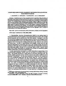
that there are many types of trust-region methods. In our paper, the LevenbergMarquardt method is utilized; see [13, 27]. All our computations are carried out with AFEPack, a generic C++ adaptive finite element library [21]. 4.1. Example 1. In the first example, we consider the planar linear elasticity problem in an L-shaped domain (see Figure 1). The parameters (λ, µ) = (2, 1) are 0.5
0.4
0.3
0.2
(ρ,θ)
0.1
0
−0.1
−0.2
−0.3
−0.4
−0.5 −0.5
−0.4
−0.3
−0.2
−0.1
0
0.1
0.2
0.3
0.4
0.5
Figure 1. L-shaped domain. estimated using the exact displacement given as follows 1 1 u = u∗ + φ + ϕ, λ+µ µ where
µ
¶µ ¶ cos γθ sin γθ α , − sin γθ cos γθ β µ ¶ µ ¶ − cos πx1 cos πx2 sin πx1 cos πx2 φ(x1 , x2 ) = , ϕ(x1 , x2 ) = , sin πx1 sin πx2 − cos πx1 sin πx2 u∗ (ρ, θ) = ργ
with α = β = γ = 21 , and f is given by µ ¶ µ ¶ sin πx1 cos πx2 − cos πx1 cos πx2 2 2 2µ + λ f =2π + 2π . − cos πx1 sin πx2 sin πx1 sin πx2 µ+λ On the boundary ΓD of the domain, we set uD = u. The polar coordinate (ρ, θ) is shown in Figure 1. We let the initial values of parameters to be m0 = (5, 0.6)T . A typical mesh resulting from the application of our error estimator is shown in the left plot of Figure 2. It is obvious that the refinement is mainly around the origin. The reason is that the stress is singular at the origin. A comparison of the accuracy achieved on the uniform mesh and our adaptive mesh is made and the result is shown in Table 1, where DOF represents the degrees of freedom of the mesh. It turns out that the adaptive finite element method using our error estimator produces a mesh with obvious savings in degrees of freedom for a prescribed accuracy level.
ADAPTIVE FINITE ELEMENT METHODS 0.5
0.5
0
0
−0.5 −0.5
0
0.5
−0.5 −0.5
27
0
0.5
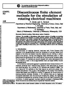
Figure 2. Left: Typical meshes produced by our error estimator with distributed measurement. Right: Typical meshes produced by our error estimator with point-wise measurement. In some applications, measurements can be obtained only at distinct points. Assume that the measurements are given by values of the state variable at six different points: (x1 , y1 ) = (−0.2, 0.3), (x2 , y2 ) = (−0.4, 0.3), (x3 , y3 ) = (−0.2, −0.3), (x4 , y4 ) = (−0.4, −0.3), (x5 , y5 ) = (0.3, −0.2), (x6 , y6 ) = (0.3, −0.4). The mesh resulting from the application of our error estimator is shown in the right-hand plot of Figure 2. During the test, we add random noise such that the observation z is computed from z(xi , yi ) = u(xi , yi ) ∗ (1 + δκ) for a random number κ in [-0.5, 0.5] with δ as the noise level. The errors in km − mh k with different noise levels are shown in Figure 3. It indicates that when the noise is large, the errors in the parameters are large as well. Moreover, with a high level of noise, the errors in the parameters cannot be reduced efficiently by the mesh refinement. For instance: in case δ = 10%, further mesh refinement does not produce much more accuracy. However, when the noise level is low, the errors in the parameters can be reduced considerably by the mesh refinement. Finally, we investigate the quantitative behavior of the estimator by computing the effectivity index of the error estimator, which is defined by Ief f = km − mh k2 /(η12 + η22 ). The result is shown in Table 2 and it indicates that our error estimator is sufficient for guiding efficient mesh refinement. Table 2. The effectivity index of the error estimator. DOF 119 429 1550 2301 3042 3161 3348
km − mh k2 4.763e-3 1.840e-3 8.642e-4 3.878e-4 1.665e-4 7.520e-5 3.142e-5
η12 + η22 9.660e-3 4.524e-3 2.230e-3 1.110e-3 5.509e-4 2.768e-4 1.395e-4
Ief f 0.493 0.407 0.388 0.349 0.302 0.272 0.225
28
T. FENG, M. GULLIKSSON, AND W. LIU 0
10
δ=10% δ=5% δ=1% δ=0.1%
−1
Error
10
−2
10
−3
10
−4
10
2
3
10
10
4
10
Total number of degrees of freedom
Figure 3. Error reduction in km − mh k for the different noise levels. It is important to remark that, in the point-wise measurement case, care must be taken in selecting the size of ². In our finite element codes, the integration is carried out using classical Gauss quadrature rules and accuracy is directly correlated to the number of Gaussian points used in each element. Therefore, the size of the support of k² (x − xi ), equal to 2², should be selected with respect to the mesh size h of the element containing the point xi . Some suggestions can be found in [25], where some numerical experiments are carried out to show a possible good choice of the size of ². A mesh that is efficient for our parameter estimation problem will depend not only on the forward problem, but also on the objective function. In general, a mesh efficient for the discretization scheme of the parameter estimation is quite different from a mesh suited for the forward problem. For instance, the mesh refinements will not be around the measurement points for the point-wise case by only considering a mesh suited for the solution of the forward problem. Of course, for this particular case, we know the probable refinement areas a priori so that it is possible to investigate a priori local mesh refinements, which is impossible in general. Here we report investigations on a priori local mesh refinements and comparisons with our adaptive mesh refinement strategy. The main idea is to use a priori knowledge about the singularity of the forward solution and the measurement points to determine mesh densities of the elements near the corner and the measurement points [2, 3]. We first tried a priori indicators of power type defined by r > 0 X 1 0 , ηpriori = (x − xi )r τ τ where the points xi represent the measurement points and the re-entrant corner point and xτ denotes the barycenter of the element τ . It seemed that such indicators did not work well. Then we used the mollifiers k² as the indicator, which is defined in section 3. By using only the coordinator information, an a priori indicator can be constructed as XZ k² (x − xi ). ηpriori = τ
τ
ADAPTIVE FINITE ELEMENT METHODS
29
For convenience, we let ² = ²k+1 = ξ ∗ ²k , 0 < ξ < 1, k = 0, 1, · · ·, where k denotes the refinement step. In the process of mesh refinement, at each iteration, an average value ηavg is calculated and a parameter θ is defined, 0 θηavg , where ηpriori,τ = τ k² (x − xi ). In our experiments, we first put ξ = 0.8, ²0 = 0.05, the same as those defined in the objective function. The results were not satisfactory, however. Then we tried several different combinations of these parameters. For the case ξ = 0.8, θ = 0.75, different choices of the size of ²0 with the convergence results are shown in Figure 4. −1
10
priori mesh: ε =0.15 0 priori mesh: ε =0.10 0 priori mesh: ε0=0.05
Error
adaptive mesh
−2
10
−3
10
2
10
3
10
4
10
Total number of degrees of freedom
Figure 4. Error reduction in km − mh k for a priori mesh and adaptive mesh depending on the degrees of freedom. As shown in Figure 4, it is clear that an appropriate mesh generated by a priori mesh refinement strategy can produce rather accurate solutions compared to our adaptive mesh, e.g., in the case where ²0 = 0.1, although it does not seem that they can match the adaptive method in terms of accuracy. Furthermore, it is much cheaper from a computational point of view. However, it is not straightforward to select the constants in the a priori mesh grading algorithms, such as ²0 , θ and ξ; i.e., it is not easy to decide a good density of the mesh around measurement points, re-entrant corner and other parts of the domain. As we can see from Figure 4, in the case ²0 = 0.05, an a priori mesh cannot produce high-accuracy solutions. Such problems are quite common in a priori mesh approaches; see [2]. In our adaptive mesh refinement algorithm, after we define the parameter θ, the mesh is generated completely automatically with respect to the error estimators and a good balance between the refined and unrefined regions is obtained. For more details on how to choose the parameter θ, please refer to [6]. We should mention that several different values of θ have been tested for our adaptive algorithm, all with satisfactory results. Moreover, although the a priori mesh refinement strategy may manage to work for this individual problem, our goal is to produce efficient meshes for general applications. The adaptive finite element method suits this purpose. In our next parameter estimation problem, the locations of measurement points are unknown and are in fact design variables. This will lead to the following formulation: Z 1X k² (x − xi )(u(m, x) − zi )2 dx, min max m xi 2 Ω i
30
T. FENG, M. GULLIKSSON, AND W. LIU
where zi is the measurement value of u(m0 , xi ) at point xi , and we assume that m0 is the exact value of m. It is clear that we cannot design an a priori mesh refinement strategy for this problem. However, the general framework presented in this paper still works. Finally, our adaptive method is also suitable for the distributed parameter estimation problems. 4.2. Example 2. In the second example, we consider the linear elastic problem with the Neumann boundary conditions. As shown in Figure 5, a short cantilever plate of elastic isotropic material is analyzed [26]. The computational domain
Figure 5. Short cantilever plate. Ω = (0, 1)2 . The boundary conditions on the top edge of the computational domain are set to g · n = (0, −1.0), the boundary conditions on the right are set to u = 0, and the boundary conditions are set to homogeneous natural boundary conditions on the bottom and left edges. Young’s modulus E = 1.0 and Poisson’s ratio ν = 0.3. 1
0.9
0.8
0.7
0.6
0.5
0.4
0.3
0.2
0.1
0
0
0.1
0.2
0.3
0.4
0.5
0.6
0.7
0.8
0.9
1
Figure 6. Typical meshes produced by our error estimator. The exact solution for this problem is not known analytically, so we use a very fine mesh to solve the problem to get the ”exact” solution at the measurement points
ADAPTIVE FINITE ELEMENT METHODS
31
(0.2, 0.2), (0.2, 0.5), (0.2, 0.8), (0.5, 0.2), (0.5, 0.5), (0.5, 0.8), (0.8, 0.2), (0.8, 0.5), (0.8, 0.8). Typical meshes resulting from the application of our error estimator are shown in Figure 6. The mesh refinement procedures are not only around the topright corner and the bottom-right corner, where the stress is relatively larger, but also around the measurement points. A comparison of the accuracy in µ achieved on the uniform mesh and the adaptive mesh is shown in Figure 7. It can be seen that our proposed algorithm is much more efficient. We also execute some numerical computations with different observation noise levels. In Table 3, the errors in λ and µ with different noise levels are shown. Again, the result indicates that when the noise level is low, the errors in the parameters can be reduced considerably by mesh refinement. −2
10
Adaptive mesh Uniform mesh
Error in µ
−3
10
−4
10
−5
10
1
10
2
10
3
10
4
5
10
10
Total number of degrees of freedom
Figure 7. Error reduction in | µ − µh | for the uniform mesh and adaptive mesh depending on the degrees of freedom. Table 3. Computation with noisy data. δ 10% 5% 1% 0.1% 0.0%
DOF 1172 3089 3010 2910 3336
| λ − λh | 0.0885 0.0115 1.277e-3 7.220e-4 3.066e-4
| µ − µh | 4.597e-3 2.749e-3 1.628e-4 8.634e-5 3.24e-05
References [1] M. Ainsworth and J. T. Oden, A Posterior Error Estimation in Finite Element Analysis, John Wiley & Sons, New York, 2000. [2] T. Apel and F. Milde, Comparison of various mesh refinement strategies near edges, Comm. Numer. Methods Engrg, 12 (1996) 373-381. aranta, Direct and inverse error estimates for finite [3] I. Babu˘ska, R. B. Kellogg and J. Pitk¨ elements with mesh refinements, Numer. Math., 33 (1979) 447-471. [4] W. Bangerth, Adaptive Finite Element Methods for the Identification of Distributed Parameters in the Partial Differential Equations, Ph.D. thesis, University of Heidelberg, Institut f¨ ur Angewandte Mathematik, 2002. [5] D. Bates and D. Watts, Nonlinear Regression Analysis and its Applications, John Wiley & Sons, New York, 1988.
32
T. FENG, M. GULLIKSSON, AND W. LIU
[6] R. Becker and R. Rannacher, A feed-back approach to error control in finite element methods: basic analysis and examples, East-West J. Numer. Math., 4 (1996) 237-264. [7] R. Becker, H. Kapp and R. Rannacher, Adaptive finite element methods for optimization problems, Proceedings of 18th Biennial Conference on Numerical Analysis (Ed. D. F. Griffiths and G. A. Watson), p. 21-42, Chapman & Hall/CRC, 2000. [8] R. Becker and B. Vexler, A posteriori error estimation for finite element discretization of parameter identification problems, Numer. Math., 96 (2004) 435-459. [9] P. G. Ciarlet, The Finite Element Method for Elliptic Problems, North-Holland, Amsterdam, 1978. [10] G. Duvaut and J. L. Lions, Inequalities in Mechanics and Physics, Springer-Verlag, Berlin, 1976. [11] K. Eriksson and C. Johnson, Adaptive finite element methods for parabolic problems I: A linear model problem, SIAM J. Numer. Anal., 28 (1991) 43-77. [12] T. Feng, M. Gulliksson and W. B. Liu, Adaptive finite element methods for identification of elastic constants, J. Sci. Comput., 26 (2006) 217-235. [13] R. Fletcher, Practical Methods of Optimization, John Wiley & Sons, New York, 2000. [14] E. Haber, U. M. Ascher and D. Oldenburg, On optimization techniques for solving nonlinear inverse problems, Inverse Problems, 16 (2000) 1263-1280. [15] P. C. Hansen and D. P. O’leary, The use of L-curve in the regularization of discrete ill-posed problems, SIAM J. Sci. Comput., 14 (1993) 1487-1503. [16] P. C. Hansen, Rank-Deficient and Discrete Ill-Posed Problems, SIAM, Philadelphia, 1998. [17] Y. Q. Huang, R. Li, W. B. Liu and N. N. Yan, Efficient discretization for finite element approximation of constrained optimal control problems, to appear. [18] A. Kirsch, An Introduction to the Mathematical Theory of Inverse Problems, Springer-Verlag, New York, 1991. [19] K. Kunisch, W. B. Liu and N. N. Yan, A posteriori error estimates for a model parameter estimation problem, Numerical mathematics and advanced applications, p. 723-730, Springer, Berlin, 2003. [20] O. A. Ladyzhenskaya and H. H. Urlatseva, Linear and Quasilinear Elliptic Equations, Academic Press, New York, 1968. [21] R. Li, on Multi-Mesh h-Adaptive Algorithm, J. Sci. Comput., 24 (2005) 321-341. AFEPack is available online at http://dsec.pku.edu.cn/∼rli. [22] J. L. Lions, Optimal Control of Systems Governed by Partial Differential Equations, SpringerVerlag, Berlin, 1971. [23] V. A. Morozov, Methods for Solving Incorrectly Posed Problems, Springer-Verlag, New York, 1984. [24] J. Nocedal and S. J. Wright, Numerical Optimization, Springer Series in Operations Research, Springer, New York, 1999. [25] S. Prudhomme and J. T. Oden, On goal-oriented error estimation for elliptic problems: Application to the control of pointwise errors, Computer Methods in Applied Mechanics and Engineering, 176 (1999) 313-331. [26] H. Steeb, A. Maute and E. Ramm, Goal-oriented error estimation in solid mechanics, Errorcontrolled adaptive finite elements in solid mechanics (Ed. E. Stein), p. 211-261, John Wiley & Sons, 2002. [27] N. Z. Sun, Inverse Problems in Groundwater Modeling, Kluwer Academic, Netherlands, 1994. [28] R. Verf¨ urth, A Review of A Posteriori Error Estimation Techniques for Elasticity Problems, Comput. Meth. Appl. Mech. Engrg., 176 (1999) 419-440. [29] G. Wahba, Spline Models for Observation Data, CBMS-NSF Regional Conference Series in Applied Mathematics, Vol. 59, SIAM, Philadelphia, 1990. [30] Y. F. Wang and Y. X. Yuan, Convergence and regularization of trust region methods for nonlinear ill-posed inverse problem, Inverse Problem, 21 (2005) 821-838 CIPR, University of Bergen, P.O. Box 7800, N-5020 Bergen, Norway E-mail:
[email protected] Department of Engineering, Physics and Mathematics, Mid Sweden Univ., SE-851 70 Sundsvall, Sweden E-mail:
[email protected] Institute of Mathematics and Statistics, University of Kent, Canterbury, CT2 7NF, England E-mail:
[email protected]