bjinyoung79.lee @samsung.com ... This work was supported by Samsung Electronics Co., Ltd. ..... International Conference on Multimedia and Expo, no.
ADAPTIVE GEOMETRY-BASED INTRA PREDICTION FOR DEPTH VIDEO CODING Min-Koo Kanga, Cheon Leea, Jin Young Leeb, Yo-Sung Hoa a
Gwangju Institute of Science and Technology (GIST) b Multimedia Lab. Samsung Electronics Co., Ltd. a {minkoo, leecheon, hoyo}@gist.ac.kr b jinyoung79.lee @samsung.com
ABSTRACT In this paper, we propose an efficient depth video coding method for the 3D video (3DV) system. Since the boundary information of depth video significantly affects the rendering quality in the 3DV system, the proposed method reduces the loss of the boundary information by producing precise intra prediction modes. The characteristics of depth video are analyzed and considered to modify the previous geometryadaptive block partitioning in the proposed method. The proposed method guarantees a better performance of intra prediction than the method of the H.264/AVC. Experimental results have shown that 0.33 dB coding gain in terms of PSNR and subjective quality improvement of synthesized views are achieved by the proposed method. Keywords— 3D video, depth map coding, MVD, H.264/AVC, intra prediction, block partitioning 1. INTRODUCTION 3D video (3DV) and ultra high definition TV (UHDTV) technologies have been researched widely as the next generation broadcasting technologies. These expand sensation of viewers, and provide a more immersive sense of realism and the function of free viewpoint navigation [1]. Moreover, various applications of the 3DV system have been developed by the help of many related fields such as computer graphics. One of the most famous applications is free viewpoint video (FVV). It makes viewers possible to select an arbitrary viewpoint and direction within a certain range. Another famous application is 3D television (3DTV) which gives viewers 3D depth impression of captured scene. One common characteristic of these 3DV applications is a vast amount of input data to be compressed and transmitted to viewers. 3D content is usually generated by multi-camera setups or 3D modeling; thus, the amount of input data becomes larger than that of 2D content. In this point of view, both efficient 3D scene representation and 3D content compression are essential in the 3DV system, and multi-view
___________________________
This work was supported by Samsung Electronics Co., Ltd.
video plus depth (MVD) is a popular data format because of its suitability for rendering and compression [2]. Nowadays, various approaches have been proposed to compress MVD data. One of them is joint coding techniques. Oh et al. proposed motion vector sharing between color video and depth video [3]. Na et al. proposed view synthesis prediction for depth image coding [4]. This approach looks adequate with respect to depth coding efficiency. However, these techniques have a problem of quality degradation of synthesized views because of the boundary information loss in depth video. The main objective of depth data in the 3DV system is to synthesize high quality of arbitrary intermediate views, and special care of the boundary information is required for high quality of rendering view during depth video coding because the boundary information significantly affects the rendering quality [7]. In this point of view, geometry-based block partitioning for depth video coding by Kang et al. [5] is helpful signpost to preserve the depth boundaries. However, this version of geometry-based intra prediction needs to be further improved since it is less efficient and significantly dependent on the geometric structures of input sequences. In this paper, we proposed adaptive geometry-based intra prediction to solve the above problems. First, characteristics of depth video were investigated and analyzed to reduce redundancy of depth signal for its efficient compression. Second, geometry-adaptive block partitioning is borrowed and modified to preserve the boundary information. To evaluate the proposed method, depth bit rate, depth quality, and subjective quality of synthesized views are compared. 2. RELATED WORKS 2.1. Analysis on depth video and depth coding strategies Depth video has some different characteristics with color video. This makes color video codec-based techniques for depth video coding less efficient. In practice, depth video has relatively lower temporal consistency than color video because of inaccurate depth estimation. Another difference is found at the depth level distribution. Depth level is the information of relative distance between
978-1-4244-7493-6/10/$26.00 ©2010 IEEE 978-1-4244-7492-9/10/$26.00 ©2010 IEEE
ICME 2010 1230
ICME 2010
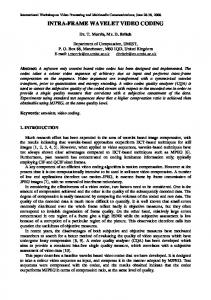
an object and a camera within an observed scene. Therefore, depth levels are quite similar within an object, but it rapidly changes around boundaries of the objects. These differences cause the following depth coding results, and these give us strategies for efficient depth coding. Less use of inter prediction modes Small prediction block aggregation around object boundaries Therefore, we need to exploit spatial correlation as much as possible because it is hard to exploit temporal correlation in depth video. Second, we have to focus on the boundaries because relatively many residual data and quantization errors occur around the regions. 2.2. Geometry-adaptive block partitioning The previous geometry-adaptive block partitioning looks appropriate for depth video coding from its strategies. This method provides an efficient intra prediction mode around object boundaries when the current block can be locally modeled as piecewise-smooth 2D signal [6], and depth video often satisfies the ideal condition because of simple depth level distribution. In the geometry-adaptive block partitioning, a prediction block for the current block is divided into three regions by an estimated line. Then, each region is independently predicted. After this, the predicted regions are combined into a single prediction mode instead of dividing the current block into sub-blocks like the quadtree-based block partitioning shown in Fig. 1. Texture 1: vertical intra prediction
(a) Quadtree-based
(b) Geometry-based
Texture 0: horizontal intra prediction
Fig. 1. Geometry-based block partitioning for intra prediction
Meanwhile, the quality of synthesis view significantly depends on the quality of object boundaries in the DIBRbased 3DV system [7], and it is possible to increase the rendering quality by increasing the quality of object boundaries of compressed depth video. Therefore, we can achieve both the improvement of rendering quality and bit saving in terms of compression ratio by applying the geometry-adaptive block partitioning scheme to object boundaries. In addition, the strategies of depth video coding provide clues for adoption of the scheme. The main differences between the previous method and the proposed method are as follows. First, the proposed method refers to the geometric structures of reconstructed neighboring blocks to divide the current block. Second, new
partitioned intra prediction modes adaptively alternate the conventional intra prediction modes of the H.264/AVC. These two main contributions make the proposed method decodable without any additional bit transmission. 3. ADAPTIVE GEOMETRY-BASED INTRA PREDICTION Characteristics of depth video provide us facilities for the adoption of the previous geometry-adaptive block partition method. First, we can easily estimate a partition function from the geometric structures of available neighboring blocks exploiting high spatial correlation of depth video signal. Second, we can briefly determine whether the current block contains a boundary or not from the information of neighboring pixels by inspecting their continuity.
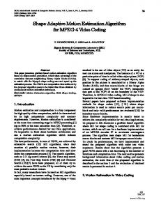
Fig. 2. Block diagram of the proposed method
The block diagram of the proposed method is described in Fig. 2. The proposed method starts with investigating the standard deviations of left neighboring pixels and upper neighboring pixels to decide whether the encoder use the proposed method or not. Since depth video signal has high spatial correlation, the most probable intra 16x16 prediction mode and directions of extrapolations can be predicted from the information of standard deviations. The following Fig. 3 shows the distribution of the standard deviations when each intra 16x16 prediction mode was selected as the best intra 16x16 predictor for “Ballet” depth sequence where the x-axis is the standard deviation of the left neighboring pixels and the y-axis represents the standard deviation of the upper neighboring pixels. From the results, we notice that each distribution is biased to a certain direction according to each prediction mode. Thus, we predict the most probable intra 16x16 prediction mode from the information of standard deviations inversely. For convenience, we divided the standard deviation plane into four divisions, and each division maps a partitioned intra prediction mode extension (PIPE) type and a position of neighboring block to be referred for the partition function estimation. PIPE type defines a set of intra 16x16 prediction modes to be constructed by the proposed method. The following Fig. 4 shows a division map according to standard deviations of neighboring pixels, and Table 1 represents PIPE types connected to the divisions. In Table 1, newly proposed prediction modes are written in italics.
1231
conducts a curve detection process to give a more natural boundary fitting. Thus, the current block is divided by an estimated line or a curve function in the proposed method.
Fig. 5. Line detection process based on Hough-transform
Fig. 3. Distribution of standard deviations according to each mode
The following flowchart shown in Fig. 6 describes how to select the best partition function. First, we conduct both linefitting and curve-fitting with the initial data set from the neighboring block. Then, the function which gives us smaller sum of square distance (SSD) between the data set and each estimated fitting function is selected as the best partition function.
Strandard deviation of upper neighborings
Start Initial data set collection
2 Line-fitting estimation
3
SSD calculation of each fitting function
10
1 0
4 Best partition function decision
x
10
Strandard deviation of left neighborings
End
Fig. 4. Division map of standard deviations of neighboring pixels
Fig. 6. Flowchart of partition function estimation
Table 1. PIPE type and neighboring block position Division PIPE type Neighbor Block Vertical, Horizontal, 1 Left, Upper DC, Plane 2 3 4
Curve-fitting estimation
Vertical + Vertical',
Upper
Median', Plane' Vertical', Horizontal', Median', Plane'
After the partition function estimation, validity of the partition function is determined by investigating the position of the neighboring pixel which the partition function passes through. The partition function should pass one of referred neighboring pixels to be valid because we suppose that the current block contains a boundary which passes through the neighboring pixels before we apply the proposed method. If the partition function is invalid, the process is terminated.
Left, Upper
Horizontal + Horizontal', Median', Plane'
3.2. Partitioning the current block
Left
3.1. Adaptive partition function estimation A partition function is required for dividing the current block into two regions. After decision of the most probable prediction mode and a position of neighboring block, a partition function is estimated from the geometric structures of the selected neighboring block. Figure. 5 shows the general process for a line detection using well known Hough-transform. The proposed method additionally
In this step, partition equations are established using the estimated parameters of the partition function. If a line is estimated as a partition function, it has two line parameters (ρ′, θ′). Otherwise, it has three parameters (a′, b′, rad′) for a curve function. Equation (1) and Eq. (2) are partition equations for the line-based partitioning when the left and the upper neighboring blocks were referred, respectively. Similarly, Eq. (3) is the partition equation for the curve-based partitioning.
1232
Using these partition equations, the position of the current pixel (xi, yj) is included into one of two regions (negative or positive) according to the output sign of partition equations, and this is described in Fig. 7. The constants w and h represent the width and height of referred neighboring block, respectively. f ( xi , y j ) = ( xi + w) sin θ '+ y j cosθ '− ρ '
(1)
f ( xi , y j ) = xi sin θ '+ ( y j + h) cos θ '− ρ '
(2)
f ( xi , y j ) = ( xi + w − a ' ) 2 + ( y j + h − b' ) 2 − rad '
(3)
methods with available neighboring pixels. Then, the predicted regions construct a single partitioned intra prediction mode. In this manner, a set of partitioned intra prediction modes is produced according to a PIPE type, and the shape of the partitioned current block is determined by an estimated partition function. These new partitioned intra prediction modes alternate the conventional intra 16x16 prediction modes. Thus, bits to signal new prediction modes are not necessary. Figure 8 describes examples of partitioned intra prediction modes when PIPE type is two.
ρ' 0
θ'
yj Region 0
Referred left block
Estimated partition line from left block
Region 1
w
y
x
xi
A line-based block partitioning ρ'
0
x
θ' Referred upper block
h
xi
Estimated partition line from upper block
yj Region 0 Region 1
Fig. 8. Partitioned intra prediction modes when PIPE type is two (Upper: line-based, Bottom: curve-based)
y
A line-based block partitioning 0
x
(a', b') Region 0
Referred upper block
h
rad' xi Referred left block
y
w
yj
Estimated partition curve from both left and right blocks
Region 1
A curve-based block partitioning Fig. 7. Partitioning the current block into two regions
3.3. Partitioned intra prediction mode extension Once the current block is divided into two regions based on the estimated partition function, each region is independently predicted using various directional prediction
In the case of PIPE type 2, three line-based or curvebased intra prediction modes (Vertical', Median', Plane') are generated depending on the selected partition function instead of the conventional horizontal, DC, and plane intra prediction modes. These are rarely selected as the best intra 16x16 mode when the information of the standard deviations belongs to division 2 from Fig. 3. Thus, we can allocate the mode numbers for the conventional modes to the new partitioned intra prediction modes. In this way, the most probable mode (mode number 0) plus three partitioned intra prediction modes construct the final candidates for the best intra 16x16 prediction mode competing each other with respect to rate-distortion. First, Vertical' mode predicts each partitioned region with vertical direction, and it alternates the conventional horizontal prediction mode (mode number 1) where the region that vertical prediction is impossible is predicted with the median value of its neighboring pixels. Similarly, Median' mode predicts each partitioned region with the median value of its
1233
available neighboring pixels, and it alternates the conventional DC prediction mode (mode number 2). Finally, Plane' mode predicts each partitioned region with the same direction of the partition function slope, and it alternates the conventional plane prediction mode (mode number 3).
4. EXPERIMENTAL RESULTS We have extended the conventional intra16x16 prediction method of H.264/AVC with the proposed method, and it is implemented in the JM reference software, version 14.2. The simulation conditions are presented in Table 2. The former QP range was applied for “Lampshade2” and “Flowerpot” to shows a generic coding performance, and the latter QP range was applied for “Ballet” and “Mobile” to compare the quality of synthesized views at high QPs because the rendering quality is clearly degraded at high QPs; so, it makes easy to evaluate the effect of the proposed method, which particularly cares object boundaries, on the synthesized views. The test sequences are shown in Fig. 11. We have tested various types of depth data considering various 3D video applications. Table 2. Simulation conditions Lampshade2 ( 433x370), Test sequences Flowerpots (437x370), Ballet(1024x768), Mobile(720x540) GOP structure Intra only frame 22, 27, 32, 37 (Lampshade2, Flowerpots) QP 31, 34, 37, 40 (Ballet, Mobile) Common FRExt profile, CABAC
Fig. 9. Partitioned intra prediction modes when PIPE type is four (Left: line-based, Right: curve-based)
In the same manner, three partitioned intra prediction modes (Horizontal', Median', Plane') are generated when PIPE type is four as shown in Fig. 9. Newly generated modes alternate the conventional prediction modes (vertical, DC, and plane) except for the most probable prediction mode (horizontal). In the case of PIPE type 1, we cannot expect the most probable prediction mode because all prediction modes are randomly selected as the best intra 16x16 prediction mode in the division one. Thus, the conventional method is conducted in this case.
Lampshade2
Flowerpots Ballet Fig. 11. Test sequences
Mobile
Experimental results are shown in Table 3 in terms of BDBR (Bjonteggard Delta BitRate) and BDPSNR (Bjonteggard Delta PSNR) [8]. Most results are calculated from the single depth video, but the synthesis results are calculated from the summation bitrate of a pair of left and right depth videos and the quality of synthesized views. This experimental frame work is considered in current MPEG activity for 3D video coding technology standardization [9]. Figure 12 shows rate-distortion curves of “Lampshade2” and “Flowerpots”. The results show that our proposed method provides higher coding performance than the method of the original H.264/AVC with respect to ratedistortion.
Fig. 10. Partitioned intra prediction modes when PIPE type is three (Left: line-based, Right: curve-based)
On the other hand, all conventional intra 16x16 prediction modes are alternated by the four partitioned intra prediction modes (Vertical', Horizontal', Median', Plane') when PIPE type is three.
1234
Sequence Lampshade2 Flowerpots Ballet Mobile
Table 3. Experimental results Viewpoint BDBR 5th -2.98% 5th -1.54% 3rd -0.54% 5th -0.76% 4th (synthesized) -0.13% 5th -3.29% 7th -3.03% 6th (synthesized) -4.03%
BDPSNR 0.29dB 0.10dB 0.05dB 0.06dB 0.05dB 0.33dB 0.18dB 0.26dB
The performance difference between two “Mobile” views was caused by the quality difference of them. As shown in Fig. 13, 5th view has sharper boundaries than that of 7th view; as a result, the 5th view showed the better coding performance as much as 0.33dB.
proposed method produces efficient partitioned intra prediction modes around boundaries in depth video. Moreover, characteristics of depth video: smooth depth level change and sharp depth level variation nearby object boundaries are utilized in our proposed method to improve the performance. As a result, the proposed method showed better coding performance as well as subjective quality.
Fig. 14. Subjective quality comparison of synthesized view (Top-left: real view, Top-right: synthesized view without compression, Bottom-left: result of the H.264/AVC method, Bottom-right: result of the proposed method)
Fig. 12. R-D curves “Lampshade2” and “Flowerpots”.
6. REFERENCES “Mobile” depth video (Left: 5th view, Right: 7th view)
“Ballet” depth video (Left: 3rd view, Right: 5th view) Fig. 13. Zoom in images of input sequences
In the case of “Ballet” depth videos, relatively low coding performances were shown because they have nonhomogeneous depth levels even in an object and complex form of boundaries as shown in Fig. 13. Nevertheless, its synthesized view showed better subjective quality shown in Fig. 14. The top-left shows the original 6th view, and topright shows the synthesized 6th view from 5th and 7th depth videos without compression. The bottom-left shows the synthesized 6th view when used depth videos are compressed by the H.264/AVC. The final bottom-right shows the synthesized 6th view when the used depth videos are compressed by the proposed method. These results indicate that our proposed method would contribute to subjective quality improvement of a synthesis view even if coding gains of depth views were not significant. 5. CONCLUSIONS In this paper, we proposed an adaptive geometry-based intra prediction method for depth video coding. The
[1] A. Smolic, K. Mueller, P. Merkle, C. Fehn, P. Kauf, P. Eisert, and T. Wiegand, “3D video and free view-point videotechnologies, applications and MPEG standard," IEEE International Conference on Multimedia and Expo, no. 4037061, pp. 2161-2164, July 2006. [2] P. Merkle, A. Smolic, K. Mueller, and T. Wiegand, “Multiview video plus depth representation and coding," International Conference on Image Processing, vol. 1, pp. I201-I204, Jan. 2006. [3] H. Oh and Y.S. Ho, “H.264-based depth map sequence coding using motion information of corresponding texture video,” PSIVT, pp. 898-907, Dec. 2006. [4] S.T. Na, K.J. Oh, C. Lee, and Y.S. Ho, “Multi-view depth video coding method using depth view synthesis,” IEEE International Symposium on Circuits and Systems, pp. 14001403, 2008. [5] M.K. Kang, J. Lee, J.Y. Lee, and Y.S. Ho, “Geometry-based block partitioning for efficient intra prediction in depth video coding," SPIE Visual Information Processing and Communication, Vol. 7543, pp. 75430A-75430A-11, Jan. 2010. [6] C. Dai, O.D. Escoda, P. Yin, X. Li, and C. Gomila, “Geometryadaptive block partitioning for Intra prediction in image and video coding,” IEEE International Conference on Image Processing, Sep. 2007. [7] Kwan-Jung Oh, Sung-Yeol Kim, and Yo-Sung Ho, “Depth reconstruction filter for depth coding,” IET Electronics Letters, Vol. 45, No. 6, pp. 1-2, March 2009. [8] ITU-T Q.6/16, “Calculation of average PSNR differences between RD-curves,” VCEG-M33, March 2001. [9] ISO/IEC JTC1/SC29/WG11, “Draft report on experimental framework for 3D video coding,” N11273, Dresden, Germany, April 2010.
1235