transform are implemented in the SVC reference software JSVM 4.0 as additional prediction modes. Experimental results demonstrate coding gains up to 1 dB ...
Improved Interlayer Prediction for Scalable Video Coding Wenxian Yang, Gagan Rath and Christine Guillemot INRIA-IRISA, France
Abstract— In this paper, we present a novel technique for efficient compression of enhancement layers in scalable video coding (SVC). First we propose an improved interlayer prediction scheme which exploits the inherent redundancy of the underlying Laplacian pyramid with nonbiorthogonal filters. Secondly we introduce an orthogonal transform in parallel with the current 4x4 transform to improve the coding efficiency of the enhancement layer further. The improved prediction and the transform are implemented in the SVC reference software JSVM 4.0 as additional prediction modes. Experimental results demonstrate coding gains up to 1 dB for I pictures, and up to 0.7 dB for both I and P pictures, over a current implementation.
Index Terms— Scalable video coding, Laplacian pyramid, Spatial scalability
layer is used to improve the prediction for the macroblocks (MBs) with high directional characteristics. In this paper, we propose to improve the enhancement layer prediction using the current upsampling and downsampling filters. The improved prediction is based on the inherent redundancy of the LP structure with nonbiorthogonal upsampling and downsampling filters. The proposed method can be applied in both open-loop and closed loop configurations. To improve the coding efficiency of the enhancement layer further, we use a recently proposed orthogonal transform in conjunction with the existing 4x4 transform. We incorporate the proposed method in the JSVM software and present the results with respect to a current implementation. II. L APLACIAN PYRAMID REPRESENTATION
I. I NTRODUCTION Scalable video coding (SVC) is currently being developed as an extension of the ITU-T Recommendation H.264 |ISO/IEC International Standard ISO/IEC 14496-10 advanced video [1]. It allows to adapt the bit rate of the transmitted stream to the network bandwidth and/or the resolution of the transmitted stream to the resolution or rendering capability of the receiving device. In the current SVC reference software JSVM, spatial scalability is achieved using layers with different spatial resolutions. The higher resolution signals, commonly known as enhancement layers, are represented as difference signals where the differencing is performed between the original high resolution signals and predictions on a macroblock level. These predictions can be spatial (intra-frame), temporal, or interlayer. The lower base layer signal along with the associated interlayer-predicted enhancement layer signal constitutes the wellknown Laplacian pyramid (LP) representation [2]. In the context of scalable video coding, the compression of the enhancement layers is an important issue. In the SVC standard, for the enhancement layer blocks coded with interlayer predictions, the decoder follows the standard LP reconstruction, i.e., it interpolates the base layer and adds the enhancement layer to the interpolated signal. Do and Vetterli [3] have proposed to use a dual frame based reconstruction which has a better rate-distortion (R-D) performance. The dual frame construction, however, requires biorthogonal upsampling and downsampling filters, which limits its application in SVC because of noticeable aliasing in lower resolution layers. To improve upon this drawback, the authors in [4], [5] have proposed to add an update step for the base layer signal at the LP encoder. This structure, however, necessitates not only an open loop LP structure but also the design of a new lowpass filter. An alternative approach to improve the compression efficiency of enhancement layers is to employ better interlayer predictions. To that end, several techniques have already been proposed to the JVT [6], [7], [8]. In [6], optimal upsamplers are designed which depend on the downsampling filter, the quantization levels of the base layer, and the input video sequence. Later, a family of downsamplers are constructed to span a range of filter lengths, aliasing and ringing characteristics available to an encoder [7], together with their corresponding upsamplers. In [8], the direction information of the base
1424407281/07/$20.00 ©2007 IEEE
The Laplacian pyramid [2] represents an image as an hierarchy of differential images of increasing resolution such that each level corresponds to a different band of image frequencies. For convenience of notation, let us consider an LP for 1-D signals; the extension to the 2-D case with separable filters is straightforward. For the sake of explanation, we will here consider only one level of decomposition. Considering an input signal x of N samples and dyadic downsampling, a coarse signal c can be derived as c = Hx,
(1)
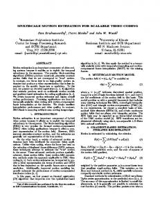
where H denotes the decimation filter matrix of dimension (N/2) × N . H has the following general structure: 2 3 .. . 6 7 6. . . h(2) h(1) h(0) . . . . . . . . . . . . . . . . 7 7 H=6 6. . . . . . . . . . . . . . . . h(2) h(1) h(0) . . .7 . (2) 4 5 .. . The coefficients h(n), n = 0, 1, 2..., here denote the downsampling filter coefficients. In the SVC framework, the LP coefficients need to be quantized before being encoded. Depending on whether the quantizer for the low resolution signal is inside or outside the prediction loop, there can be two different structures for the LP. The open-loop prediction structure with the quantizer outside the loop is shown in Fig. 1. In this structure, the detail signal dol is given as dol = x − Gc = (IN − GH)x,
(3)
where IN denotes the identity matrix of order N and G denotes the interpolation matrix of dimension N × (N/2). G has the following general structure: 2 3t .. . 6 7 6. . . g(0) g(1) g(2) . . . . . . . . . . . . . . . 7 7 (4) G=6 6. . . . . . . . . . . . . . . . g(0) g(1) g(2) . . .7 . 4 5 .. . The coefficients g(n), n = 0, 1, 2..., here denote the upsampling filter coefficients and the superscript t denotes the matrix transpose operation.
I 649
ICASSP 2007
c x
down−samp. filter h(n)
M
M
up−samp. filter g(n)
dol
−
cq
Qc Qd
This signal can be always computed by the decoder once it receives the low resolution signal c. We can thus reduce the correlation by upsampling this difference signal and subtracting it from the detail signal as follows:
dq
d�ol
Fig. 1. Open-loop Laplacian pyramid structure with one decomposition level
Fig. 2. level
down−samp. filter h(n)
M
Qc
M
up−samp. filter g(n)
dcl
Qd
−
dq
x − (2IN − GH)Gc,
p�ol = (2IN − GH)Gc = (2IN − GH)pol .
In the closed-loop configuration, as depicted in Fig. 2, the quantizer is within the prediction loop, and the prediction of the high resolution signal uses the quantized low resolution signal. If cq denotes the quantized low resolution signal, the detail signal is obtained as (5)
Irrespective of the configuration, the coarse signal c and the detail signal are encoded with suitable transforms and VLC coding schemes before being transmitted to the decoder. In JSVM, the closed-loop prediction structure is adopted because of its superior performance compared to the open-loop structure. Note that the coarse signal and the detail signal here refer respectively to the base layer and the interlayer-predicted enhancement layer in the JSVM.
p�cl = (2IN − GH)Gcq .
Consider first the open-loop configuration. When the upsampling and the downsampling filters are biorthogonal, HG = IK [3]. In this case, the detail signal obtained by the standard prediction does not contain any low frequency component. This can be easily seen by downsampling the detail signal: 2
(6)
Therefore the correlation between the coarse resolution signal c and the detail signal is equal to zero. Biorthogonality is a constrained relationship between the downsampling and the upsampling filters: if the two filters are concatenated, the resulting filter is a half-band filter which is symmetric about the frequency π/2 [5]. A sharp roll off of the decimation filter will require that the upsampling filter has an overshoot close to π/2. This has a negative impact on the compression efficiency of enhancement layers. Therefore the filters used in the JSVM are usually nonbiorthogonal. Nonbiorthogonality, however, creates correlation between the low resolution coarse signal and the detail signal. This can be seen from the following equation: Hdol = H(IN − GH)x = (IK − HG)Hx = (IK − HG)c.
(7)
Since HG �= IK , the right hand side is nonzero. The above equation can also be rewritten as (8)
where pol denotes the open-loop prediction. This shows that the low frequency component in the detail signal is equal to the difference between the coarse signal and the downsampled prediction signal.
(11)
(12)
Thus the new detail signal is obtained as d�cl = x − (2IN − GH)Gcq .
Hdol = H(IN − GH)x = (H − HGH)x = 0 N ×1 .
(10)
Note that the correlation between the newly obtained detail signal and the coarse signal is still nonzero because of the nonbiorthogonality. However, it can be shown that the new correlation is less than the original correlation. Since the detail signal undergoes quantization after transform coding, and the downsampling and upsampling operations increase the complexity, we do not iterate the above operation further. The open-loop configuration suffers from the mismatch between the predictions at the encoder and at the decoder. The decoder receives the quantized low-resolution signal cq and therefore would make the prediction by substituting c by cq in Eqn. 11. Like the standard prediction in closed-loop configuration, this drift can be eliminated by including the quantization of the low resolution signal in the prediction loop. This will give the new prediction in the closedloop configuration as
III. I MPROVED PREDICTION
Hdol = (IK − HG)c = c − Hpol ,
=
(9)
denotes the new detail signal. Equivalently, we can obtain where the new prediction signal as
Closed-loop Laplacian pyramid structure with one decomposition
dcl = x − Gcq .
dol − GHdol = x − Gc − G(IK − HG)c
d�ol
cq
x
=
(13)
Like the original detail signal, the new detail signal is transformed, quantized and entropy-coded before being transmitted. IV. T RANSFORM C ODING OF E NHANCEMENT L AYER The detail signal undergoes an orthogonal transform before being quantized and entropy coded. The transform aims to remove the spatial correlation in the detail signal coefficients and to compact its energy in fewer number of coefficients. The current SVC standard, for this purpose, uses a 4×4 integer transform, which is an approximation of the discrete cosine transform (DCT) applied over a block size of 4×4. The DCT, however, may not be the optimal transform since the detail signal contains more high frequency components. A closer look at Eqn. 3 reveals that the detail signal has certain inherent structure. Most of its energy is concentrated along certain directions which are decided by the downsampling and the upsampling filters. These directions can be found out by the singular value decomposition of IN − GH as follows: IN − GH = U ΣV t ,
(14)
where U and V are N × N orthogonal matrices and Σ is an N × N diagonal matrix. In [9], we have shown that, in openloop configuration with biorthogonal upsampling and downsampling filters, either the U matrix or the V matrix applied on the detail signal leads to a critical representation of the LP. We refer to these matrices as the U-transform and the V-transform respectively. The 4 × 4 integer transform applied in the JSVM is referred to as the DCT hereafter. Under the closed-loop configuration, the above structure is somewhat weakened. The introduction of the quantization noise in the
I 650
prediction loop destroys the redundancy structure of the LP. Nevertheless, the above matrices are orthogonal and can always be applied to the original detail or the newly obtained detail signal. The decoder can use the transpose of these matrices for the inverse transformation. Experimental results presented in [9] showed that the V-transform had a slightly better R-D performance than the U-transform. Therefore, for the actual implementation with JSVM, we consider only the Vtransform.
TABLE I AVERAGE NUMBER OF MB S FOR MODE SELECTION OVER 8 INTRA FRAMES FOR CITY SD AT DIFFERENT QP S . QP QCIF/CIF 18,18
24,24
V. I MPLEMENTATION WITH JSVM As we have mentioned earlier, in the current JSVM software, the interlayer prediction is implemented in the closed-loop mode. For I, P, and B frames, the selection of prediction modes (interlayer, spatial-intra, temporal, etc.) is based on a rate-distortion optimization procedure. The closed-loop structure does not guarantee an improved rate-distortion performance either with the modified prediction or with the V-transform; the performances can vary depending on the local signal statistics. Thus, to apply the proposed method in the SVC, we propose three additional modes employing the improved prediction and the V-transform besides the current inter-layer prediction mode. The proposed three modes are (i) current interlayer prediction followed by V-transform (d+ V-Transform), (ii) improved prediction followed by DCT (d� +DCT), and (iii) improved prediction followed by V-transform (d� +V-transform). We refer to the current interlayer prediction mode followed by DCT as ”d+DCT”. The mode selection statistics over several intra frames is shown in Table I. These statistics were obtained by including all macroblock (MB) modes in the JSVM software, and then selecting the modes with rate-distortion optimization (without changing the JSVM λ parameter). The improved prediction and the V-transform were applied to only the SD layer while the QCIF and CIF layers were coded using the existing modes. The table shows the number of macroblocks undergoing different modes for different QP values of QCIF, CIF and SD layers over 8 Intra frames of the ’CITY’ video sequence. Note that the total number of 16x16 macroblocks in SD layer is equal to 1584 (=704x576/16x16), and therefore the (no of macroblocks) entries in each row add to 1584. First we observe that majority of blocks choose the improved prediction, especially at high QP values of SD. Secondly, the number of blocks following V-transform is significant at low QP values of QCIF and CIF. Overall, the proposed modes seem to be the chosen ones for low QP values of CIF and QCIF layers. It is also clear that the number of MBs selecting the spatial intra mode is much smaller than the number of MBs selecting the inter layer prediction modes. Thus, we propose to suppress the spatial intra mode, and include the other three inter-layer prediction modes. More specifically, the MB modes used in original JSVM and the proposed encoding scheme for I and P frames are defined as in Table II. Note that all the 8 × 8 modes are valid only when fidelity range extension (FRExt) is enabled. Accordingly, the syntax for coding MB modes are also modified. Since we removed the spatial intra mode, only one extra flag BLTransformFlag is needed in the syntax for signaling the MB modes. This flag is encoded using the context adaptive binary arithmetic coding (CABAC). Note that the V-transform is applied over macroblocks of size 16x16 for the luma component and of size 8x8 for the chroma components. Over a macroblock of size 16x16 (luma) or 8x8 (chroma), the order of complexity is about the same as that of the current 4x4 transform except that the operations use floating-point numbers. In the proposed modes d+V-transform 4x4, d+V-transform 8x8, d� +Vtransform 4x4, and d� +V-transform 8x8, the suffix 4x4 or 8x8 refers
SD 30 36 42 48 30 36 42 48
Spatial Intra 21.25 13.625 2.125 0 33.125 16 2 0
d�
d DCT 189.875 182.125 179.625 176.375 465.875 384.5 383 384.375
V-trans. 76.125 18.25 2.75 0.625 164.75 67.5 7.75 0.25
DCT 739.125 988.75 1289.875 1370.125 578.375 763 1075.375 1161.75
V-trans. 557.625 381.25 109.625 36.875 341.875 353 115.875 37.625
TABLE II D EFINITION OF MACROBLOCK MODES FOR I AND P FRAMES IN JSVM AND PROPOSED ENCODING SCHEME . For I frames: JSVM
Spatial-intra Inter-layer texture Inter-layer texture
Proposed
Intra 4x4, Intra 8x8 (d+DCT) 4x4, (d+DCT) 8x8 (d+DCT) 4x4, (d+DCT) 8x8 (d+V-trans) 4x4, (d+V-trans) 8x8 (d� +DCT) 4x4, (d� +DCT) 8x8 (d� +V-trans) 4x4, (d� +V-trans) 8x8
For P frames: JSVM
Proposed
Spatial-intra Temporal Inter-layer texture Inter-layer MV/resi. Temporal Inter-layer texture
Inter-layer MV/resi.
Intra 4x4, Intra 8x8 Skip, Inter 16x16, Inter 16x8, Inter 8x16, Inter 8x8 (d+DCT) 4x4, (d+DCT) 8x8 IntraBLSkip, Inter 4, Inter 8, Inter 16 Skip, Inter 16x16, Inter 16x8, Inter 8x16, Inter 8x8 (d+DCT) 4x4, (d+DCT) 8x8 (d+V-trans) 4x4, (d+V-trans) 8x8 (d� +DCT) 4x4, (d� +DCT) 8x8 (d� +V-trans) 4x4, (d� +V-trans) 8x8 IntraBLSkip, Inter 4, Inter 8, Inter 16
to the blocksize for zigzag scanning of the transform coefficients. VI. E XPERIMENTAL R ESULTS AND A NALYSIS The proposed scheme is tested using standard video sequences CITY and HARBOUR, and the anchor results are obtained by JSVM 4.0. In the encoding of 3 spatial layers, i.e., QCIF, CIF and SD, the proposed method is only applied between the CIF layer and the SD layer. Thus, only the coding results of the SD layer are presented. Since FGS layers are not involved in our experiments, we set both QPs for QCIF/CIF to 18, which approximately correspond to the base layer quality with the initial QP 36 plus three FGS layers. First we test the proposed method using 64 intra frames. Then we test the proposed method using the GOP structure defined as GOPSize=1 and IntraPeriod=8, which means one I frame followed by 7 P frames for every 8 frames. Other parameters in the configuration files are listed as follows: FRExt: off for QCIF layer, on for CIF/SD layers; Loop Filter: on; Update Step: 0; Adaptive QP: 1; Inter Layer Pred: 0 for QCIF layer, 2 for CIF/SD layers; Number of FGS layers: 0. Results for all Intra frames are shown in Fig. 3, and the results with P frames are shown in Fig. 4. The results demonstrate that up to 1 dB gain in PSNR can be achieved with all intra frames, and up to 0.7 dB gain can be achieved with Intra and inter P frames. We must note here that, for all the simulations, we did not modify the entropy coding that follows the transform (DCT or V-transform). In the current JSVM software, it is implemented as context adaptive
I 651
City Sd, over 64 IP frames, QP=18 for QCIF/CIF, luminance
City SD, over 64 intra frames, QP=18 for QCIF/CIF, luminance 36
37
35 36
34 35
PSNR (dB)
PSNR (dB)
33 34 33 32
31 30
31 30 29 8000
32
9000
10000
11000
12000
13000
JSVM-18
29
proposed-18
28
14000
JSVM-18 proposed-18
27 4000
15000
4500
5000
5500
6000
6500
Bitrate (kbps)
Bitrate (kbps)
(a) CITY
(a) CITY
Harbour SD, over 64 IP frames, QP=18 for QCIF/CIF, luminance
Harbour SD, over 64 intra frames, QP=18 for QCIF/CIF, luminance
37
38
36
37
35 34 PSNR (dB)
PSNR (dB)
36 35 34
33 32 31
33
30
JSVM-18
29
proposed-18
JSVM-18
32 31 10000
proposed-18
10500
11000
11500
12000
12500
13000
13500
28 6000
14000
7000
8000
9000
10000
11000
12000
13000
14000
15000
Bitrate (kbps)
Bitrate (kbps)
(b) HARBOUR
(b) HARBOUR Fig. 3. PSNR-rate curves for the luminance component of (a) CITY and (b) HARBOUR SD 30Hz over 64 intra frames, when QPs for QCIF/CIF are 18.
variable length coding (CAVLC). The current zigzag scan and the coding scheme are optimized for the DCT; therefore we expect better results if the scanning and encoding of the V-transformed coefficients are modified so as to suit the characteristic of the V-transform. This is a subject of research and we will not pursue it in this paper. VII. C ONCLUSIONS In this paper, we have proposed a novel interlayer prediction scheme for spatially scalable video coding. The proposed scheme exploits the inherent redundancy of the underlying Laplacian pyramid with nonbiorthogonal filters by rendering the enhancement layer signal less correlated with the base layer. The simplicity of the prediction scheme is reflected by the fact that it did not require to modify the current upsampling filter nor did it need any update structure. Moreover, the method can be incorporated both in the openloop and in the closed-loop configurations. Along with a recently proposed transform for the enhancement layer, the proposed prediction scheme was integrated with JSVM in the SD layer. Based on the experimental results, the macroblock modes in I and P frames were redesigned. Results with test sequences demonstrated that the proposed scheme achieves better R-D performance compared to the original prediction modes. The performance improvement was significant in the case of low base layer QP suggesting potential application of the proposed method in highquality scalable video coding.
Fig. 4. PSNR-rate curves for the luminance component of (a) CITY and (b) HARBOUR SD 30Hz over 64 I and P frames, with GOP size = 1 and Intra Period = 8, when QPs for QCIF/CIF are 18.
R EFERENCES [1] JVT, “Joint Scalable Video Model JSVM-4,” in Joint Video Team (JVT) of ISO/IEC MPEG & ITU-T VCEG (ISO/IEC JTC1/SC29/WG11 and ITU-T SG16 Q.6), Nice, France, Oct. 2005. [2] P. J. Burt and E. H. Adelson, “The Laplacian pyramid as a compact image code,” IEEE Trans. on Comm., vol. Com-31, pp. 532–540, Apr. 1983. [3] M. N. Do and M. Vetterli, “Framing pyramids,” IEEE Trans. on Signal Process., vol. 51, pp. 2329–2342, Sept. 2003. [4] M. Flierl and P. Vandergheynst, “An improved pyramid for spatially scalable video coding,” in Proc. IEEE ICIP 2005, Genova, Italy, Sept. 2005. [5] D. Santa-Cruz, J. Reichel, and F. Ziliani, “Opening the Laplacian pyramid for video coding,” in Proc. IEEE ICIP 2005, Genova, Italy, Sept. 2005. [6] A. Segall, “Study of upsampling/down-sampling for spatial scalability,” in Joint Video Team (JVT) of ISO/IEC MPEG & ITU-T VCEG (ISO/IEC JTC1/SC29/WG11 and ITU-T SG16 Q.6), Nice, France, Oct. 2005. [7] A. Segall, “Upsampling and down-sampling for spatial scalability,” in Joint Video Team (JVT) of ISO/IEC MPEG & ITU-T VCEG (ISO/IEC JTC1/SC29/WG11 and ITU-T SG16 Q.6), Bangkok, Thailand, Jan. 2006. [8] C. K. Kim, D. Y. Suh, and G. H. Park, “Directional filtering for upsampling according to direction information of the spatially lower layer,” in Joint Video Team (JVT) of ISO/IEC MPEG & ITU-T VCEG (ISO/IEC JTC1/SC29/WG11 and ITU-T SG16 Q.6), Bangkok, Thailand, Jan. 2006. [9] G. Rath and C. Guillemot, “Compressing the Laplacian pyramid,” in Proc. IEEE MMSP 2006, Victoria, Canada, Oct. 2006.
I 652