Adaptive Slicing of non-axis symmetric parts using volumetric error by ... to the volume specified by the computer-aided design model. The magnitude of this ...
Adaptive Slicing of non-axis symmetric parts using volumetric error by
Praveen Kumar (2012178)
Supervisor: Dr. Prashant Kumar Jain
Mechanical Engineering Discipline
INDIAN INSTITUTE OF INFORMATION TECHNOLOGY, DESIGN AND MANUFACTURING, JABALPUR
2015
Acknowledgement With all due respects and sincere gratitude, I would like to thanks my Supervisor, Dr. Prashant Kumar Jain, for his invaluable supervision, kind support and zealous encouragement during the pursuit of this project at the PDPM IIITDM Jabalpur. Without assistance of Advance working facility and non-destructive evaluation lab, it would be difficult to accomplish this work; I would like to pay my special thanks to Mr. Mohhamad Taufik and Mr. Shashank, who contribute their valuable time to successful completion of my project. Motivation and encouragement by friends always provided me confidence and fortitude to work. It is my pleasure to thank them.
Praveen Kumar 2012178
1. Introduction Commercial rapid prototyping (RP) systems, which build 3D objects using the layer by layer building process, introduce an error in the part because of the amount of material used compared to the volume specified by the computer-aided design model. The magnitude of this error, normally called a staircase error, varies with the nature of the surface of the part. Inclined and curved surfaces show staircase effects more predominantly than other surfaces. The orientation at which the part is built, can have a significant effect on the quality of various surfaces of the part because of this effect. The orientation of the part also affects other factors in some rapid prototyping processes [1] such as the build time, the complexity of the support structure, shrinkage, curling, trapped volume, and material flow. The undesirable staircase feature is most often apparent on sloping or curved surfaces, and it is impossible to eliminate it completely in most cases. However, the effect can be reduced by decreasing the layer thickness and by orienting the part so that the effect of the overall staircase error is greatly reduced. The determination of an appropriate orientation of the part during the building process has therefore been an important issue in rapid prototyping for improving the accuracy and quality of parts. The need for the development of an effective part orientation system can also be considered from the point of view of emerging trends in intelligent rapid prototyping. At present, the rapid prototyping procedure involves a series of discrete independent functions: creation of a CAD model, process planning for an STL file, fixture design to suit part shape and building, verification and inspection, and finishing operations if required. These require a high level of skill, judgment, and experience on the part of the designer, in order to produce an accurate and acceptable prototype. Therefore, the development of an effective part orientation system for rapid prototyping is an essential requirement for intelligent RP process planning and for the future development of an intelligent rapid prototyping environment. 2. Methodology for volumetric error computing The volumetric error in rapid prototyping processes in general, and in the FDM process in particular, can be defined as the difference in the volume of material used in building the part compared to the volume specified by the CAD model. The total volumetric error in a part will be different at different orientations because of the layering building process. If the volumetric error in a layer in the RP part can be computed, then the volumetric error in the part will be the sum of all the volumetric errors in the layers in the part. A generic algorithm has therefore been developed that computes the volumetric error, in a part of any shape, by summing the volumetric errors in each layer. The algorithm makes use of the STL model of the part, slices the part by infinite planes normal to the build direction, and then determines the best orientation based on the least amount of volumetric error in the part. The algorithm provides the user with two options for orienting the part about different axes. In one option, the user can rotate the part about one axis only (x- or y- or z-axis) to determine the best orientation angle. In the second option, the user can rotate the part about two axes (first about the z-axis, then about the x- or y-axis). We shall describe the algorithms and procedures for the second option. Figure 1 shows a flowchart describing the algorithm for rotation about two axes. When two axes are selected by the user, the algorithm works in the same manner as for one axis, except that the part is rotated first about the z-axis from a starting angle (i1 = 0), and then about the second axis (x or y) from 0 ° to 90 ° with
the specified step increment of rotation (d″). The procedure starts with the user providing the STL file of the part in the ASCII format. The user inputs the values of the step angle of rotation and the layer thickness and selects the axis/axes of rotation. If the user selects small values of the step angle of rotation and the layer thickness, a higher accuracy is expected for the best orientation angle. At the start, when the STL file is loaded into the program, the model is placed in a normal position as determined by the user and is set at 0 ° orientation. If it is not in the normal position, the user has to modify the model using the CAD software. The program displays the triangular facets of the STL model. At each orientation, the model is sliced from bottom to top by horizontal planes separated by a distance equal to the selected layer thickness. This creates a large number of intersection points (or vertices) between the facets and the plane. The vertices thus represent the part in that orientation, and the unit normal vectors represent the direction of tessellated facets with respect to the z-axis. Initially, all the vertices are an unordered collection of intersection points in the database. The program uses a sub algorithm, called a contour processor, which sorts out these vertices into groups with the same z-coordinate values. Then contours with the same z-values are created. The vertices in each contour must be reordered by the contour processor to determine the area bounded by the contour polygon. Thus, the contour processor used in the program, modifies and sorts out the vertices automatically to generate horizontal contours. When the part is oriented about any axis in a direction specified by the user, the program first determines the minimum and maximum height of the part with respect to the xy-plane. The horizontal intersecting planes are then generated to cut the part. Using the coordinate values of the vertices of each tessellated triangle, the program determines the slopes and the equation of the lines of each triangle. The coordinates of intersecting points between these lines and the horizontal planes are then determined. These intersected points or vertices are then sorted out by the contour processor in terms of the same z-coordinate values from the minimum to the maximum height of the part in the z-direction. Sorting is unidirectional, either in a descending or ascending order. Too many variations in sizes of triangles coupled with model complexity often complicate the procedure of sorting. Grouping of vertices is then performed considering the minimum and the maximum z coordinate values as the grouping criteria. The intersection points are joined by straight lines, and the program then determines the area bounded by the polygon of each contour. These contour areas are used to determine the volume difference generated by the two horizontal contours in a layer, which are then used to determine the volumetric error in that layer. Considering the horizontal layers intersecting the tessellated part, the horizontal area in each contour is given by 𝑛
1 1 𝐴𝑖 = (∑ 𝑥𝑖 𝑦𝑖+1 − 𝑥𝑖+1 𝑦𝑖 ) + (𝑥𝑛 𝑦1 − 𝑥𝑖 𝑦𝑛 ) 2 2 𝑖=1
𝑊ℎ𝑒𝑟𝑒 𝑛 = 𝑡ℎ𝑒 𝑛𝑢𝑚𝑏𝑒𝑟 𝑜𝑓 𝑖𝑛𝑡𝑒𝑟𝑠𝑒𝑐𝑡𝑖𝑜𝑛 𝑝𝑜𝑖𝑛𝑡𝑠 𝑖𝑛 𝑒𝑎𝑐ℎ 𝑙𝑎𝑦𝑒𝑟 1≤𝑖≤𝑛 𝑥𝑖 , 𝑦𝑖 = 𝑡ℎ𝑒 𝑐𝑜𝑜𝑟𝑑𝑖𝑛𝑎𝑡𝑒𝑠 𝑜𝑓 𝑖𝑛𝑡𝑒𝑟𝑠𝑒𝑐𝑡𝑖𝑜𝑛 𝑝𝑜𝑖𝑛𝑡𝑠
𝑇ℎ𝑒 𝑣𝑜𝑙𝑢𝑚𝑒𝑡𝑟𝑖𝑐 𝑒𝑟𝑟𝑜𝑟 (𝑉𝐸)𝑖𝑠 𝑔𝑖𝑣𝑒𝑛 𝑏𝑦 𝑘
𝑡 𝑉𝐸 = |∑(𝐴𝑖+1 − 𝐴𝑖 ) | 2 𝑖=1
𝑊ℎ𝑒𝑟𝑒 𝑘 = 𝑡ℎ𝑒 𝑛𝑢𝑚𝑏𝑒𝑟 𝑜𝑓 𝑙𝑎𝑦𝑒𝑟𝑠 𝑡 = 𝑙𝑎𝑦𝑒𝑟 𝑡ℎ𝑖𝑐𝑘𝑛𝑒𝑠𝑠
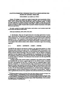
And after that slicing algorithm will be implemented START
Read STL file of the part, minimum and maximum slices thicknesses and bound on volumetric error value
find Zmin and Zmax
Set Z = Zmin
Check for the triangles at Z height and Z+t
Calculate the volumetric error b/w slice at Z and Z+t
0≤VE≤100mm3
100