application of open software solutions and FPGA circuit, Altera Cyclone EP1C6. .... Photo of a development board for astronomical camera 1. Processor ..... window, implemented control buttons in the INDI controller. In the upper part of the ...
Advanced camera image data acquisition system for “Pi-of-the-Sky” Maciej Kwiatkowski1, Grzegorz Kasprowicz1, Krzysztof Poźniak1, Ryszard Romaniuk1, Grzegorz Wrochna2 1 Warsaw University of Technology, 2Soltan Institute for Nuclear Studies, Poland ABSTRACT The paper describes a new generation of high performance, remote control, CCD cameras designed for astronomical applications. A completely new camera PCB was designed, manufactured, tested and commissioned. The CCD chip was positioned in a different way than previously resulting in better performance of the astronomical video data acquisition system. The camera was built using a low-noise, 4Mpixel CCD circuit by STA. The electronic circuit of the camera is highly parameterized and reconfigurable, as well as modular in comparison with the solution of first generation, due to application of open software solutions and FPGA circuit, Altera Cyclone EP1C6. New algorithms were implemented into the FPGA chip. There were used the following advanced electronic circuit in the camera system: microcontroller CY7C68013a (core 8051) by Cypress, image processor AD9826 by Analog Devices, GigEth interface RTL8169s by Realtec, memory SDRAM AT45DB642 by Atmel, CPU typr microprocessor ARM926EJ-S AT91SAM9260 by ARM and Atmel. Software solutions for the camera and its remote control, as well as image data acquisition are based only on the open source platform. There were used the following image interfaces ISI and API V4L2, data bus AMBA, AHB, INDI protocol. The camera will be replicated in 20 pieces and is designed for continuous on-line, wide angle observations of the sky in the research program Pi-of-the-Sky. Keywords: optical astronomy, high performance CCD cameras, optical counterparts to GRB, FPGA based image data acquisition systems, ARM microprocessors
1. „PI OF THE SKY” PROJECT Major aim of the „Pi of the Sky” [1] Project is to observe the sky for the search of optical counterparts to the Gamma Ray Bursts (GRB) [2,3]. Differently to other similar projects, the „Pi of the Sky” assumes a continuous observation of the whole sky, without any need to move a large telescope [4] after the discovery of the burst by the satellite network GRB Coordinates Networks (CGN) [5]. In order to be able to do this task, a set of 32 cameras is manufactured. They will be organized in two separately mounted matrix sub-sets containing 16 pieces each [6]. Now a simple pilot system is functioning, consisting of two cameras, localized in Las Campanas Southern European Observatory in Chile [7]. The designed and manufactured cameras are based on CY7C68013a microcontroller [8], compatible with the 8051 core, in fast version with rich peripheries, including among others the full-speed USB 2.0 device. The camera is equipped in gigabit Ethernet interface realized in the RTL8169s controller [9] with PCI bus. Data transfer between SDRAM (32MB) memory and Ethernet controller is realized via the PCI controller implemented in FPGA chip Cyclone I (EP1C6) by Altera [10]. FPGA realizes also the control of charge shift in CCD and manages digital data acquisition and stores them in SDRAM memory. The image data are first converted by the AD9826 image processor [11]. The efficiency of the system of first generation (with two cameras) is satisfactory, but its development possibilities are rather confined. The system consists of many strictly dedicated solutions including complicated VHDL blocks (as for example controllers Master/Slave PCI, SDRAM) and of 8051 microcontroller. Software for the latter was written in assembler. The software includes, among others, implementations of network protocols like IP, UDP and dedicated NUDP protocol. The degree of system complication confines the possibilities of free system development but also its efficient debugging, to a narrow circle of experts, who have been working with the system from several years. The new generation of the camera assumes the usage of widely applied technologies and protocols based on Open Source standard. All the design changes were mainly possible due to application of AT91SAM9260 (ARM926EJ-S) CPU type microprocessor by Atmel [12] which can work in the Linux OS environment.
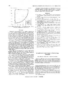
2. NEW SOLUTION FOR ULTRASENSITIVE CCD CAMERA SYSTEM FOR ASTRONOMY New implementation of the camera, including hardware and software parts, was carried on a specially designed development and redundant PCB. The PCB was presented in fig.1. The board has Image Sensor Interface (ISI) outputs [13]. The ISI is compatible with the digital video signal transmission standard by ITU: ITU-R.BT601 [14]. The processor AT91SAM9260 is equipped in this standard. More, the processor was chosen because it possesses this interface standard.
Photonics Applications in Astronomy, Communications, Industry, and High-Energy Physics Experiments 2008, edited by Ryszard S. Romaniuk, Tomasz R. Wolinski, Proceedings of SPIE Vol. 7124 71240F · © 2008 SPIE · CCC code: 0277-786X/08/$18 · doi: 10.1117/12.817943 Proc. of SPIE Vol. 7124 71240F-1 2008 SPIE Digital Library -- Subscriber Archive Copy
ISI is designed for a direct cooperation with CMOS sensors. Usage of the ISI interface is possible after the analog video signal from CCD output is processed and managed by simple logical circuits in the FPGA. The simple possibility of ISI usage was not obvious from the beginning of the system design. There are only few data in the relevant web resources concerning the usage of ISI in this role and in a similar configuration. Due to these doubts, the development board has the ability to map the FPGA circuit as a device visible in the address space of the CPU microprocessor, connected to the external bus. The FPGA chip was equipped with external SDRAM memory, serving as a buffer for image data storage. In such a configuration, a state machine implemented in FPGA would carry image data acquisition in the SDRAM. The CPU would then initiate DMA transmission from the FPGA, visible as a device on the bus, to its own SDRAM memory. After some encouraging initial tests with the usage of the ISI image interface, it is known that there is no need for a noneffective double data buffering and that the final camera PCB (not the development one) would be considerably simplified. The tests have proven that there is no need for SDRAM memory, FPGA circuit, buffers preventing blockage of the processor bus by the FPGA chip, thus the bus width may be much smaller. FOGA chip may be used of considerably smaller resources (like TQFP100) because most of these resources would be not used.
:4Im
12
'- I
____—I I
h
22
Fig.1. Photo of a development board for astronomical camera 1. Processor AT91SAM9260; 2. SDRAM memory of processor 64MB 32bit (2x32MB 16bit); 3. DataFlash 8MB memories; 4. FPGA Cyclone EP1C3 circuit; 5. SDRAM memory of FPGA (32MB 16bit); 6. Circuit of the physical layer of Ethernet (PHY) RTL8201; 7. Ethernet socket 10/100; 8. USB socket Full-Speed Device; 9. USB Full-Speed Host socket; 10. RS232 socket; 11. Debug UART socket; 12. MMC socket; 13. ISI processor’s connector; 14. ISI connector of FPGA chip; 15. UART connector; 16.
Proc. of SPIE Vol. 7124 71240F-2
I2C connector; 17. JTAG connector of FPGA chip; 18. Active Serial connector; 19. JTAG connector of processor; 20. Clock support battery socket; 21. Power supply section; 22. Power supply connector;
3. CAMERA SYSTEM CONSTRUCTION The applied processor AT91SAM9260 by Atmel is a chip based on the RM926EJS core. It has a rich set of peripheral devices. The core ARM926EJ-S, compatible with the architecture ARMv5TEJ, is characterised by the following features: hardware support for Java language, additional set of intructions for digital signal processig (DSP), unit of memory management MMU, internal bus compatible with Advanced Microcontroller Bus Architecture AMBA standard [15] and AHB - Advanced Highperformance Bus. The latter feature enables simultaneous data transfer between numerable devices of master and slave type. The kinds of master and slave devices and all possibilities of transmission between them are presented in table 1. One of the AHB master type peripheries is image ISI interface. There are numerable advantages of this solution, which will be debated in the following chapter. Two other AHB devices of master type are: data bus and processor instruction bus. The data as well as the instructions may be taken from arbitrary memory: internal SRAM memory (2x4kB), internal ROM memory (32kB) or external memory connected to the external bus (like SDRAM). The nonvolatile ROM memory contains a simple bootloader (placed there by the memory manufacturer), which seeks for a valid program (beginning with instructions for jumps in the table of interrupt vectors) in the flash memory connected to the SPI bus, and loads it to SRAM memory. The development board features a serial flash memory AT45DB642 (64Mb) [16], with programmed bootloader, provided by the manufacturer (At91 bootstrap ver 1.6). The bootloader requires only a simple configuration and compilation. Its size may not overcome the size of the internal SRAM memory, which is 4kB. Therefore its role is confined only to initiate the clock of the main processor (PLL), to configure the external SDRAM memory (64MB) and to load from the serial flash memory the following U-boot bootloader. Now after supplementing, the bootloader is a more advanced application. Depending on the configuration, it may weight a few hundred kB, and thus, there is no possibility to reduce it to the required 4kB. It is loaded to the SDTRAM. Due to its complexity it is necessary to configure the bootloader to the final system architecture. The U-boot was written based on the sources of Linux kernel. It may load and execute, among other functions, the Linux kernel. It may execute other programs outside the OS family. The bootloader has implemented a service for many devices and protocols like: mass memory - IDE, MMC, network devices and protocols –TFTP (trivial File Transfer Protocol), simple shell with many instructions which may be helpful at hardware debugging – view and modification arbitrary memory areas and processor registers. The operational system may be executed from the level of U-boot using numerable methods. To load Linux kernel, the TFTP protocol was used. It is a protocol frequently used to start stations without hard disks. After loading the kernel, U-boot gives out the control, via a jump to the loaded with the kernel, a decompression program. The kernel is decompressed and the system starts. Table 1. Transmission configuration in AMBA Bus Master 0 1 2 3 4 5 Slave Instructions Data Controller Host USB Controller Ethernet ARM926 ARM926 DMA ISI 0 Internal + + + + + + SRAM0 4kB 1 Internal + + + + + + SRAM1 4kB 2 Internal ROM + + + + _ _ 3 External bus + + + + + + 4 Internal peripheries + + + + _ _
4. CAMERA SOFTWARE Linux kernel was compiled via auto-configuration with support of BOOTP/DHCP protocol. The kernel, during the startup, receives from the DHCP server the following information: own IP address, IP address of NFS server, access path to the file system. It is possible to mount the file system which is made accessible by the NFS server. It is possible to mount the file system also from the local MMC card. The network solution is more convenient because provides a central management of many computers and their resources, even in the case of disk-less devices. A single server may store the following data for all 32 cameras: Linux kernel, separate file systems, including all configuration, start-up files, etc.
Proc. of SPIE Vol. 7124 71240F-3
Camera images may be stored on the same or separate NFS servers. The individual file and catalogue systems may be arbitrarily configured and structured. It is possible to create arbitrary scripts for Linux shell, to manage the whole configuration and to automate its execution. The configuration space of the 32 camera system is rather wide. The embedded Linux in each camera enables compilation and execution of arbitrary ready application like streaming video, web server and other more dedicated application written by the user. A number of ready controllers may be immediately used, which have direct access to the hardware, like: I2C, SPI, GPIO. One may implement own kernel modules. A dedicated controller was written for the ISI image interface. The controller is compatible with the standard „Video for Linux v2” (V4L2 API) [17]. This module registers data from a video device and also registers and reserves one of the SPI interfaces of the processor. The ISI interface serves for sending the video data stream, while the interface SPI serves for setting of the internal camera registers like: status, start/stop control, exposition time, amplification, etc. The interface I2C is used most frequently to communicate with the registers of integrated SMOS sensors. Also, a simpler SPI interface may be used for this purpose. The camera registers, the control automation for image data transmission and acquisition from CCD sensor, all were implemented in the FPGA circuit residing on the camera development board. The compatibility of the controller with V4L2 enables usage of an arbitrary video application, which makes the camera system very flexible and cooperative.
5. ISI VIDEO INTERFACE The signals in the ISI interface are shown in fig.2. The data are sent via a serial bus which is 8-bit wide DATA[7..0] and is synchronized by a clock ISI_PCK (pixel clock). The signals ISI_VSYNC and ISI_HSYNC serve for synchronization of the beginning and end of the frame for each image line. Between the valid lines and frames, there are sent addititional data (blanking intervals). All signals, together with the pixel clock are generated by the image sensor. The market offers a wide variety of SMOC image sensors, thus, the ISI interface may be configured differently. The configuration includes signal polarization, data format, etc. The accepted image formats are: RGB 8:8:8, RGB 5:6:5, YCbCr 4:2:2 and gray scale up to 12-bit resolution.
Image Frame
ISI_VSYN9J
--
1 linia ISI_HSYNC
pp
Pt
+
IS IPC K JTFU LTLLftftJ1 - iLLUlfUJTLUlfL
DATA [7..YCbYCrYCb .O]ccxcccrcccccx YCrYCbYCr Fig.2. Signals in ISI interface
The ISI interface has two possible data paths: the first is codec path predicted for image data transfer for data storing in file, the second is preview path with frame scaling ability, predicted for visualization of the image on the LCD screen. Both paths have nondependent FIFO register queues. The data are sent, via the master AHB interface of the AMBA bus, directly to the indicated memory area. The preview path has the ability to set a list of indicators for successive frames to be displayed. The preview path converts data to the RGB format which is accepted by LCD displays. The codec path converts image data to YCbCr format, where the luminance components may be under-sampled – or loss compressed. The conversion coefficients are set in the internal registers of the ISI interface. The K20 camera is equipped with a monochromatic CCD chip by STA [18], of 2048x2048 (+14 dark columns) resolution. Very good noise parameters of the analog channel of the camera allowed for application of an image processor which samples the analog video signal with the resolution of 16-bit. It is not advisable to reduce the acquired image resolution to 12-bit, which is offered by the ISI interface in the grey scale work mode. Therefore, to send data to the memory via the ISI interface, the YCbCr 4:2:2 mode was used. This format is as follows: 4 samples of luminance Y,
Proc. of SPIE Vol. 7124 71240F-4
2 samples of chrominance Cb and 2 samples of chrominance Cr. Four samples of the image (pixels) in this format are stored via 8 bytes (samples are 8-bit). Exactly the same number of bytes is needed to store 4 pixels of a monochromatic image of the 16-bit resolution. A drawback of such a solution is the lack of usage of the preview path with scaling ability. However, the ISI interface, in a monochromatic work mode, offers also a single data path, without the ability of hardware conversion. The maximum size of the transmitted image is 2048X2048, thus, the additional dark columns, which are accessible in the CCD sensor of STA, may not be transmitted. It is not a big drawback because they are used only during the device calibration procedures. Additionally, a test work mode of the camera may be implemented, where a shift for the read out image may be activated, to uncover the dark columns, at the cost of loss of the equivalent number of active columns. A big advantage of the ISI interface is the ability to sent a big amount of data totally in the hardware domain, not engaging in any way the CPU. A diagram of data flow, starting from the analog signal, is presented in fig.3. The video signal may be read out simultaneously from two outputs of the CCD chip, which increases two times the readout speed. The analog signal, after pre-amplification, is processed by the image processor AD9826. The charge shift clock of the CCD chip and other control signals of image processor are generated by the state machine implemented in FPGA chip. The same automation receives processed image data and sends them via the ISI interface. OLJTI
2x8bit
0UT2
Fig.3. Block diagram for data flow on the astronomical camera development board. The external sensor, or as like in this cace – the FPGA circuit, palys a role of a mater device, i.e. sends data on the bus DATA[7..0], generates pixel clock and synchronization signals H and V. The ISI interface is visible as a slave device from the side of the ARM processor. It has to be fast enough to receive the sent data and re-sent them to the SDRAM memory. This process of fast data transmission is considerably facilitated by an inbuilt DMA controller with the ability of transmission initialization in the internal bus of the processor (AHB master device). It is necessary to properly set the priorities of arbitration in the AHB bus, to avoid conflicts with other devices of master type which may request the usage of SDRAM memory. The same memory serves for storing processor instructions and data. The most critical situation
Proc. of SPIE Vol. 7124 71240F-5
leads to the ISI internal buffer overfill (or a different device of master type) and data loss. During commissioning tests of the camera, after proper initialization of the AHB bus, such situation was never observed. The inbuilt FIFO register queues and nondependent cache memories for the processor data and instructions contribute essentially to the increase of the system efficiency. The development board, in the case of not mounted CCD chip, is tested by pattern images generated by the FPGA chip. The development board possesses the ISI connector. K20 camera has test pins compatible with ISI connector. Thus, it was possible to test the physical readout of the CCD chip. There were considerable problems with glitches and other interferences generated in the connecting cables. Test results were, however, favorable. The processor uses SPI bus for communication with FPGA chip registers. The registers are responsible for camera settings and control like: exposition time, start/stop of CCD chip readout, status checking. The FPGA chip has a small memory serving for storing of data of the state machine. The programmable state machine is responsible for generation of control signals of charge shift in CCD chip. Thus, it is possible to generate, by a set of graphical tools, binary files describing the control signals and loading them during the work of the device.
6. V4L2 COMPATIBLE VIDEO CONTROLLER Video device controller in Linux has a standardized structure video_device, which wraps, a well known structure file_operations from the area of sign device controllers. Similarly to sign devices, the video device must be registered in the system. This is done by the function video_register_device. This function obtains, initiated previously, a video_device structure and an identifier determining a type of the device. A family of video devices is very broad. They may perform a lot of functions like: input or data output, video streaming, data transmission during blanking intervals, teletext devices, overlay devices or with direct access to the memory area of the imaging hardware, etc. CCD camera is registered as a device of VFL_TYPE_GRABBER type, or hardware for image registration. The structure of file_operations contains indicators for methods typical for sign devices like: open, release - these indicators assign or release access to the device, ioctl – this indicator configures the device, and write, read. All of these indicators should be implemented respectively for the output and input devices, on condition that the device is not of the overlay type. In a device of the overlay type, the user applications do not call read and write, because the video stream is sent directly to the memory, exactly to the frame buffer. For the controller to be compatible with API video ver.2, the ioctl method indicator of the file_operations structure should be set for the function video_ioctl2. The function is an internal method of the V4L2 system. All calls of ioctl are redirected into separete functions of callback type. The V4L2 system, in 2.6.19 kernel, has 79 separate functions of this type. Video devices need initialization and setting of all native work parameters, to work properly. All these parameters, usually in quite a number, have to be accessible in the user area via the ioctl calls. The new version of video API for Linux splits a single controller method into numerable calls, because very frequently a code of the function was too long and unreadable. The indicators of all of these methods are included in the structure video_device and their implementation was left to the programmer. Not all of the methods, and usually most of them, need not to be implemented in a particular application. In our case it was 10 methods which were implemented for K20 astronomical camera controller. All the methods are called from the user level with the aid of known ioctl method with an appropriate parameter and data structure. The methods may be divided to types get, set and listing functions of available options for a particular parameter, like current image resolution, other resolutions availability of the device, set appropriate resolution. All CCD camera settings are included in the registers implemented in the FPGA chip. The access to this registers is realized by by the SPI bus. The camera controller registers and uses one of the SPI ports of the processor. Apart from setting of image parameters it is possible to control the camera like: start/stop exposition of CCD chip, checking of camera status, start of ISI transmission, etc. ISI transmission is of DMA type. Therefore, the role of the controller of read method is confined only to switching on the ISI transmission in FPGA chip and to waiting for an interrupt after the transmission is over. In the next turn, the buffer is copied to the user area. The buffer for DMA transmission of ISI interface must be a continuous device because this device does not support the transmission of scatter-gather type, or to a non-continuous are of the memory. Linux operates on virtual memory, or the processor physical memory is divided into frames (fragments), which are noncontinuous in the physical memory. The virtual memory increases the system ability to operate in the address space. The
Proc. of SPIE Vol. 7124 71240F-6
address space for Linux is 4 GB, which is 1GB for the kernel area and 3GB for the user area. The address space does not depend on the available physical memory which is in the case of our camera only 64MB. As a result of the allocation functions calls, like malloc in the user area, and kmalloc in the kernel area, a determined number of memory frames is assigned to the process. These frames are not continuous in the physical memory. Some of the DMA devices accept a list of indicators - scatterlist. It is possible to initiate the DMA transmission to a noncontinuous buffer in a physical memory. The ISI interface is unable to do this. Linux offers continuous allocation functions for memory areas, but for allocations of small buffers. The dimension of camera image frame is greater than 8MB. It is possible to enforce the allocation for such a large buffer, for example with the aid of NOFAIL flag. It is, however, a brutal method which may cause system instability because it may force the release of virtual memory frames of important OS processes. In order to obtain a continuous and large memory area a simple method was applied. The mem parameter is forwarded to the kernel during the system start-up. The parameter determines the size of available operational memory. Despite the fact that the available memory on the development board is 64MB, the system is informed only of availability of 55MB (mem=55MB). The upper 9MB of the memory is not occupied by the system and would not be divided to pages. The access to the relevant reserved memory area may be obtained from the controller level. It is done by calling a function ioremap. The address of the gained buffer is forwarded to the DMA controller of ISI interface. After the transmission is over, the buffer is copied to the user area. It is a single drawback of this solution. However, at this size of the memory, only the buffer scatter-gather is mapped directly to the user area. It is not a big drawback since the memory is copied very fast and does not cause any delay during the transmission process.
7. INDI PROTOCOL INDI (Instrument Neutral Distributed Interface) [19] is a dissipated protocol serving for the control of astronomical equipment. It was designed by E.C.Downey from ClearSky Institute and is further developed as an Open Source project [20]. INDI is based on the architecture client-server-controller, what was presented in fig.4.
INDI DriverA-- DevX
INDI Client I
Iient2indiseer INDI Driver-- DevY INDI Driver C - Dev I
INDI Client
Client processes
DevZ
NET
Server
sockets processes
UNIX pipes
Driver
Hardware
processes
devices
Fig.4. Block diagram of Open SOurce INDI interface of client-server-controller type The server and INDI controller processes are executed directly on the camera board. Thus, the INDI controllers have direct access to the device, in practice via the controller of OS. The aim of the server is to execute a controller process or many processes like: camera, automatic concatenation, weather station, and directing the requests to these devices originatingfrom a single or multiple user applications. The controller process includes a description of all device functions and is responsible for execution of requests from the clients. A list of functionalities is sent to the client, which generates a dynamic graphical user interface (GUI). In this way, INDI separates a low level device functionality from high level application of the user. An arbitrary function added to the device must be only described and implemented in the controller, and the client application may turn it accessible for the user. Adding of a new device is confined only to implementation of its INDI controller. The controller consists usually from a single file c or CPP, which is compiled and linked with INDI framework libraries (indidrivermain.o, eventloop.o, liblilxml.a, libindicom.a). Wit the aid of API function of INDI
Proc. of SPIE Vol. 7124 71240F-7
protocol, all control buttons are added to the controller file (buttons, slides, checkboxes, edition fields, binary objects, etc.) necessary to run the device. Then, the functions ISxxx() are implemented for them, which are called by functions main() by the framework together with communications transmitted from the clients. One of the functions family ISxxx() is a function ISGetProperties(), which sends a list of all control buttons, and it is the first function called by the client. The calls of ISxxx() contain implemented service for all functions of the device under control.
I
The result of functions is returned to the client by the call IDxxx(). The most popular client applications, which implement INDI protocol are KStars and XEphem. The latter is an extended program, also designed by the ClearSky Institute and available as Open Source. It may be used free of charge for research purposes or private. Before making connection to INDI server it is necessary to set a proper IP address and a port on which a connection is requested. A window called INDI configuration serves for this purpose.
J m m !•• a J . ml __ a
rni
rnrea
rni ILIHI a ua
aua
urn
Irn I I
J fl a.J urn aua aua
Port: H
H fl/-j + H fl/S +
AfflLi!A!iIi
A!i!!A!L
I I
I nuvnas
J1trnfl ahj mu
J1trnfl ahj TAI
I I I
Close
Fig.5. Configuration panel of INDI interface
Proc. of SPIE Vol. 7124 71240F-8
H
+
H
+
H
b1fi4 +
—
I
rnfl
+
—
H fl/S + b1fi4 + H fl/S + H
JIjt.i* S
-I-
-*i,i, i..Iril S
+ mrn V
1LWLSM
IU !fl!
S !i Fjamj's. S IL.iTh!!1
na
== (;.j.j
n
S fl.rnjs
Sj[ni F1U ,r.l.I
=
Sjr
.4
•1
nr
S j LSD
Fig.6. Control panel of INDI interface This windows enables setting of attribute names for automatic mounting controller, in such a way that it is possible to trace a given object in the sky, as well as attribute names for weather station. After setting the server parameters the operator goes to the window INDI control panel (fig.6). In the lower part of this windows, there is a button connect. Pressing this button releases, in the middle part of the window, implemented control buttons in the INDI controller. In the upper part of the window, there are printed communications originating from the server and controllers. The controller buttons of the first test implementation of the CCD camera controller were divided to three groups: Driver connection, which enables connection with V4L2 controller, CCD control grouping functions combined with the camera servicing and management, and FPGA control group enabling loading of a new firmware for the FPGA chip or access to an arbitrary register of the camera in the test work mode. After the exposition is released Set Exposure in the window Sky View, there is presented a pattern generated in FPGA chip embedded in the camera development board, fig.7. The INDI server may give access to more controllers for successive devices like: automatic mounting for camera revolution, the weather station monitoring telescope system safety, including protection form wind, rain or snow and excessive moisture, etc. Exemplary controlling buttons for devices are presented in fig. 8.
Proc. of SPIE Vol. 7124 71240F-9
LJ I [11
IWADifLtDil
______ jJ
Fig.7. Sky View window of the sky image data acquisition system
Proc. of SPIE Vol. 7124 71240F-10
]rItj] :s.EJ ] PLJ.9]
I.
______I 5 1*1 ,I
-IF1•]
o irjJ.a
Ala jilL Th nl:I
mm] bPj*.! a
•'
S _____I
Ala 111W
j!;1
flU! flI F1jj%1
pn
IiFrrfl
S
S'i,i Ik.l!ls
V+
S ___I unr ml !WmTIl 21]
,I. S
I
•]Ii _____ S ___I
[l.Is.,, S
[kIIl:.
r [W Fig. 8. Exemplary controllers in INDI server
Proc. of SPIE Vol. 7124 71240F-11
CAMERA
—/
( Internetilntranet
)
Client cations
INDI Client
Applications Fig.9. Measurement data flow (image) from the CCD chip, via all software components, and Ethernet to the user application.
8. ADVANTAGES OF ARCHITECTURE OF THE NEW CAMERA Architecture of the new camera is based on ARM9 processor, which enables direct running of the system contained on a single PCB, working under Linux OS. Such a solution opens a wide possibility to use widely accessible applications of Open Source type. All software components of the camera are based on Open Source standard. Thus, they are transparent and may be openly modified and dynamically fit to the current system needs. Flow of the measurement data (images) from the CCD chip, via all software components, Ethernet network up to the user application, was presented schematically in fig.9. Due to the fact that the camera PCB has a video controller compatible with V4L2 standard, it is possible to run INDI server as well as an arbitrary server for video streaming (VSS) like FFmpeg. The latter server enables data acquisition in an arbitrary video application compatible with V4L2 like Mplayer. It is possible to run video application directly in the OS of the camera. In our case it is not necessary because the camera set works in a remotely controlled astronomical laboratory. The Mplayer and FFmpeg are able to service only standard control buttons of the camera, which are compatible with V4L2, such as exposition time, amplification, etc. The user controller buttons are compatible only with dedicated applications like cooling of the CCD chip. Fitting of these applications to users needs is not difficult, because program sources are available. The INDSI framework provides a number of tools enabling implementation of own client
Proc. of SPIE Vol. 7124 71240F-12
applications. It is possible to integrate the new solution of camera with the existing software of the „Pi of the Sky” based on test2K2K application. The integration process may be done via V4L2 interface as well as using INDI protocol.
REFERENCES [1] Web page of „Pi-of-the-Sky” [grb.fuw.edu.pl] [2] A.Burd, M.Ćwiok, H.Czyrkowski, R.Dąbrowski, W.Dominik, M.Grajda, M.Husejko, M.Jegier, A.Kalicki, G.Kasprowicz, K.Kierzkowski, K.Krupska, K.Kwiecińska, L.Mankiewicz, K.Nawrocki, B.Pilecki, L.W.Piotrowski, KT.Poźniak, R.S.Romaniuk, R.Sałański, M.Sokołowski, D.Szcygieł, G.Wrochna, W.Zabołotny, Pi of the Sky – all-sky, real-time search for fast optical transients, New Astronomy, vol.10, no.5, April 2005, pp.409-416 [3] M.Ćwiok, H.Czyrkowski, R.Dąbrowski, W.Dominik, G.Kasprowicz, K.Kwiecińska, K.Małek, L.Mankiewicz, M.Molak, J.Mrowca-Ciułacz, K.Nawrocki, L.W.Piotrowski, P.Sitek, M.Sokołowski, J.Użycki, G.Wrochna, Search for optical counterparts of gamma ray bursts, Acta Physica Polonica, vol.37, no.3, March 2006, pp.919-924 [4] A.Burd, H.Czyrkowski, R.Dąbrowski, W.Dominik, M.Grajda, G.Kasprowicz, L.Mankiewicz, S.Stankiewicz, G.Wrochna, Low noise CCD cameras fro wide field astronomy, Proc. SPIE, vol. 6159, February 2006, pp.160-166 [5] Strona internetowa satelitarnej sieci koordynacyjnej rozbłysków gamma całego nieba [gcn.gsfc.nasa.gov] [6] M.Ćwiok, L.Mankiewicz, K.Nawrocki, M.Sokołowski, J.Użycki, G.Wrochna, Full Pi of the Sky system and simulation, Proc.SPIE, vol 6937, December 2007, pp.693702:1-9 [7] Web page of European Southern Observatory [eso.org] [8] Controler CY7C68013A [cypress.com/products] [9] Controler RTL8169s [realtek.com.tw/products] [10] Altera Cyclone EP1C6 circuit [www.datasheetsite.com/datasheet/EP1C6] [11] Image processor AD9826 [analog.com/en/prod] [12] Processor ARM926EJ-S [arm.com/products/CPUs/ARM926EJ-S] [13] Video controller ISI [isi96.com/PHY-products/video-cores] [14] Video transmission standard ITU-R.BT601 [category.alldatasheet.com/ITU-R.BT601] [15] AMBA standard [javvin.com/networkingterms/AMBA] [16] Memory chip AT45DB642 [atmel.com] [17] Interface API V4L2 [v4l2spec.bytesex.org] [18] Web page Semiconductor Technology Associates [sta-inc.net] [19] Web page INDI transmission protocol [indi.sourceforge.net] [20] Web page of Clear Sky Institute [clearskyinstitute.com/]
Proc. of SPIE Vol. 7124 71240F-13