Nov 26, 2013 - of thorns nopal vegetable (Opuntia ficus indica) in an automated ... promoting oxidation and shortening the shelf life of the cactus [2, 3].
Automated system for acquisition and image processing for the control and monitoring boned nopal. E. Luevano, E de Posada, M. Arronte, L. Ponce, T. Flores. Centro de Investigación en Ciencia Aplicada y Tecnología Avanzada, Altamira. Instituto Politécnico Nacional, México, Km. 14.5 Carretera Tampico-Puerto Industrial Altamira, Altamira Tamaulipas C.P 89600 www.cicataaltamira.ipn.mx ABSTRACT This paper describes the design and fabrication of a system for acquisition and image processing to control the removal of thorns nopal vegetable (Opuntia ficus indica) in an automated machine that uses pulses of a laser of Nd: YAG. The areolas, areas where thorns grow on the bark of the Nopal, are located applying segmentation algorithms to the images obtained by a CCD. Once the position of the areolas is known, coordinates are sent to a motors system that controls the laser to interact with all areolas and remove the thorns of the nopal. The electronic system comprises a video decoder, memory for image and software storage, and digital signal processor for system control. The firmware programmed tasks on acquisition, preprocessing, segmentation, recognition and interpretation of the areolas. This system achievement identifying areolas and generating table of coordinates of them, which will be send the motor galvo system that controls the laser for removal Keywords: Image Processing, Laser ND:YAG, Nopal vegetable.
1. INTRODUCTION The nopal is a food typical of Mexico and its consumption is growing in different countries. The nopal vegetable belongs to Opuntia genus, Cactáceas family. They are native to America tropical and subtropical, are characterized by stems or cladodes as pallets, which are flat, succulent and articulated, commonly called in México pencas, reaching up to 60-70 cm in length. On both sides of cladodio there are dots called areolas, having in their cavity thorns, which are generally of two types: some small, grouped in large numbers (glochidia) and others large they are, according to some botanists, modified stems [1]. For consumption of nopal, these spines need to be removed, despite attempts machining done in recent years, predominantly manual method, which use blades that sweep the surface of the nopal, due to irregularities in the leaves, you get to lose up 30% of its useful volume. On the other hand the damage caused by the blades of the leaf bark allow release of mucilage promoting oxidation and shortening the shelf life of the cactus [2, 3]. The laser boned equipment developed at CICATA IPN, uses a continuous laser Nd: YAG with a wavelength of 532nm, this laser does a scan on the surface of the cactus using galvos engines, the spines are detected due to the fall the intensity of the reflected light that they cause, then a second laser pulsed Nd: YAG, but with a 1064nm wavelength longitude eliminates spines detected. Image processing is the set of mathematical algorithms applied to images in order to find properties within them. The external attributes such as size, shape, color and texture of the objects to be analyzed, can be evaluated based on the processing and analysis of images obtained by different analog and digital media. The image processing techniques have been used in fields as disparate as agriculture, biomedicine, astronomy, etc. [4, 5, 6]. Our main interest is to create an automated system for acquisition and image processing that allows the location of the areolas of nopal, create a table with the positions and send their coordinates to a galvo motor system that controls the laser for boned. Avoiding scanning the surface of the cactus and knowing the precise location of the areolas are expected to increase in the productivity of equipment up to 50%.
8th Iberoamerican Optics Meeting and 11th Latin American Meeting on Optics, Lasers, and Applications, edited by Manuel Filipe P. C. Martins Costa, Proc. of SPIE Vol. 8785, 87858X © 2013 SPIE · CCC code: 0277-786X/13/$18 · doi: 10.1117/12.2016743 Proc. of SPIE Vol. 8785 87858X-1 Downloaded From: http://proceedings.spiedigitallibrary.org/ on 11/26/2013 Terms of Use: http://spiedl.org/terms
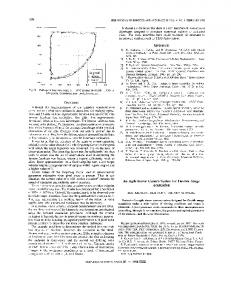
2. SYSTEM DESIGN The structure diagram of the system is showed as figure 1, the main system consists charge-couple device (CCD) for image acquisition, video decoder, memory for images, data and programs, as well as digital signal processor, which will controls the equipment. Segmentation and image processing algorithms are obtained using MATLAB and SIMULINK toolbox in link with the CCS software.
Crystal 27Mhz
VCXO RS232
Sensor CCD
Video Decoder
DSP DM6437
DDR2 Memory
Video Out JTAG
POWER
RESET
Fig. 1. The structure diagram of the complete system.
The CCD camera will be connected directly to the TVP5146 video decoder, once acquired the signal, the decoder will convert the images to digital format YCbCr. After receiving the images, the digital signal processor DM6437 will take the image data and will applied image processing and recognition algorithms that have been programmed into it. The results will be displayed on a monitor through DSP VPBE interface. A. Image Acquisition Image acquisition module consist of camera with CCD technology, the image quality requirements are very strict, the nopal vegetable images collected by camera must be able to clearly seen. The output of CCD is an analog signal, but the system need digital signal for analysis and processing data, so we use TVP5146 video decoder device. Continuous analogous data obtained by CCD will be sent directly to the TVP5146, and this will convert the digital data using its internal analog-to-digital converter. The decoder device will show the image using the format the output YCbCr. B. Image Processing Module Image processing module must be controlled for a device able to capture data image and perform processing tasks in a short time so that the equipment can work in real time. It should have enough space for storage of data, programs, and a good interface with other devices. Based on the literature consulted [7, 8, 9] we have selected the TI DM6437 device as the system's main processing device. This device is a high performance processor systems for audio processing, digital imaging and video, has a frequency of 600 MHz and processing capacity of up to 4800 MIPS, DSP core has the operational flexibility and high speed drivers numerical processing capacity matrices. It also has video accelerator and internal subsystems video and image processing. C. Memory The DSP includes a memory controller for DDR2 SDRAM with 32-bit bus, so system was added 2 memories of 64 Megabytes DDR2 type for a total of 128 megabytes for storing images, data and programs. In addition the DM6437 using two-level caching structure, first one is divided into program cache, which contains 256Kb memory space, and the
Proc. of SPIE Vol. 8785 87858X-2 Downloaded From: http://proceedings.spiedigitallibrary.org/ on 11/26/2013 Terms of Use: http://spiedl.org/terms
second level cache contains 640Kb for data memory space. The second level cache contains 1Mb memory space, the cache structure of DM6437 improve its operating efficiency.
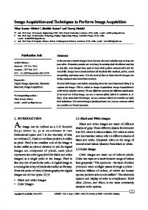
3. SYSTEM WORKFLOW Fig. 2 demonstrates the step and data flow chart. There are seven parts in this method, including converting original image to contrast image, set threshold by histogram, segmentation, recognition and interpretation, labeling and send of coordinates of areolas to galvo engines system which directs the laser. Input original signal Converting YCbCr to intensity
Operator Sobel
Pre-process
Recognition and interpretation
Set threshold by histogram
Labeling and assign coordinate pair to objects
Send coordinates to laser
Fig. 2. Flow Chart
The image processing software in the DSP operates in the following manner, the system will receive a video signal and perform a sampling of this signal every 10 seconds, the acquired image is in YCbCr color format where the brightness (Y) is the portion of the signal related to the amount of brightness in any point of the image, this is defined by the following equation. Y(x,y)= WRR (x,y)+ (1-WB - WR)G(x,y)+ WBB(x,y) The chroma (U and V) is linear factors of the difference between the value of the luminance and color planes red and blue of RGB models. These values are specifically defined as: 0.5 1−!"!
= (! !, ! − ! !, ! )
0.5 1−!"!
= (! !, ! − ! !, ! )
Cb!= !
C r= !
Once you the system have captured the image, converting process to YCbCr to RGB format is done, the Following equation describing the conversion of an YCbCr Color format into the RGB Color [10]: !(!, !) 1.000 !(!, !) = 1.000 !(!, !) 1.000
0.000 −0.344 −1.773
!(!, !) 1.403 −0.714 = !"(!, !) !"(!, !) −0.000
Proc. of SPIE Vol. 8785 87858X-3 Downloaded From: http://proceedings.spiedigitallibrary.org/ on 11/26/2013 Terms of Use: http://spiedl.org/terms
The RGB color model is based on the combination of the primary colors red (R), green (G), Blue (B), now the system should convert into a contrast intensity image. There are several colour space transformations to obtain a good representation of this colour. The next linear form is formulated as example [11]: I(x, y) = kr R(x, y) + kg G(x, y) + kb B(x, y) ,
x = 1,2,….M and y =1,2,….N
The segmentation by threshold method is one of the best known methods in image processing. The basic idea is to use an image of gray scales to establish a threshold between objects in the image and its background. In two dimensional image of M+N, X’ gray values denoted f(I,j) at coordinate (i,j), assume that t is a gray-scale threshold of this image, then the principle of based on the threshold value t segmentation between the objectives and background, it can determine threshold value through the use of histogram [11]: Target part : 0= ,if f (x,y)< t Background part : 1= ,if f (x,y) > t The output is a binary map that contains two values ‘0’ and ‘1’, binary image. Subsequently use Sobel operator for detection of edges in the image, the edges are considered as points in an image in which the intensity in a given direction changes dramatically, being detected through own local change of intensity or color in the image. The coefficient matrix for this operator is defined as [10]:
H sx =
! !"
−3 −10 −3
0 0 0
3 10 3
and Hsy =
! !"
−3 0 3
−10 0 10
−3 0 3
The result of the Sobel filter produces local gradient estimates for all pixels of the image in the two different directions, is desirable to use this type of representation because instead of processing a large amount of data is processed a simple structure that contains the same information. The procedure continues to apply a series of filters to remove white spots or objects that do not correspond to the size of areola. Finally are recognized objects in the images, labeling each one with an integer that ranges from 1 to the number of all objects in the image. Then proceeds to locate the center of each, assigning a pair of coordinates (x, y).
4. SOFTWARE IMPLEMENTATION To simplify realization of the above algorithm on DSP DM6437, we used Matlab and Simulink environment. Such an approach allows for debugging the algorithm on a general- purpose computer, and then porting it to the desired platform. The Simulink model, which realizes image-processing algorithm, is presented in the next figures. La figure 3a shows the main module made in Simulink to code generation for signal processor, the model has two subsystems, figure 3b shows the first unit for color processing is responsible for change to format RGB the video stream components Y, Cb and Cr, and applied the segmentation using proper threshold based on their histogram previously calculated, these components usually are resized to a lower sample size for processing [12], this was accomplished by inserting a resize block for each video, finally one logical operator connects all the signals, the filtering module subsystem (figure 3c), is a morphological filters that perform erosion and dilation operation using a reference structure already defined.. There are various types of structures, when is use a dilatation structure, its adds a layer of n pixels to the objects in the image, the opposite occurs when the same structure performs the erosion operation, so that a layer of n pixels is extracted from the objects in the image. With this module was possible eliminating the dots that not belong to any nopal thorns.
Proc. of SPIE Vol. 8785 87858X-4 Downloaded From: http://proceedings.spiedigitallibrary.org/ on 11/26/2013 Terms of Use: http://spiedl.org/terms
Image processing algorithm to nopal vegetable de-thorning.
Blob
Oul
In1
MATLAB
Cenhoid
Function
Analyse
MATLAB Fm
BBox Filtrado
Puke
Centros objetos
Generator
Cb
R
R
G
bran mantea G
CO 800 DM643x
G
(Square)
B
YCbCrF YCDCr
CD
B
Pk
Video Display Interleave
Cr
Variables
Dru. Madres
Video 0
Interleave
Insert Text Operaciones Color
Fig. 3a.
Compir. TO Cproli
1
R.m. R.ut.
Comparo
1ConWnö CO
D.16R37EVY
rCbCr -
C0060
gEAn
VW,
Y Cp
VIto Colon
D.mhE.n.
VsE.e C.pl.s.
Dorton...
C.
k
Y
I Cp YCtrlo aae
; r mmp
_,
'Sc, ompM.
T ConWnO
G.
g
C
.m..p1-__--Celos Sp.,.
Comoro,. Compre T
C.ml.nit
Dp.rMor
C.mpin T. ConrT.nM
Comp.,
T. Conn, 0
Fig. 3b.
W-III.,
_F
Erode
Dilate
Erosion
Dilation
I
Sobel Edge
Int
Out.]
Edge Detection
Fig. 3c. Fig, 3a. Main module to image processing, Fig, 3b. Color processing unit, Fig, 3c. Morphological filters unit.
Proc. of SPIE Vol. 8785 87858X-5 Downloaded From: http://proceedings.spiedigitallibrary.org/ on 11/26/2013 Terms of Use: http://spiedl.org/terms
5. EXPERIMENTAL RESULTS The encoding and transmission system that is used in Mexico is the National Television System Commitee (NTSC), therefore is the employ this system, the illumination was in conditions normal, CCD was adjusted so that image brightness, gain and color, were neither too dim or saturated. In this section are presented the results of use the image processing firmware designed applied to image from nopal Opuntia ficus indica. Fig. 4a is an YCbCr image that contains a nopal with several kinds of thorns; the original image is converted into a contrast, this image has a pre-processing included (Fig. 4b).
4
la
1
Fig 4a
Fig 4b
Fig. 4a. YCbCr Image, Fig 4b. Grayscale image with contrast improved and noise filtering.
The next step was the conversion of the gray intensity image to logical format, which is represented in Matlab, as an array of pixels that contains only ones and zeros. Fig. 5 shows the result of processing.
Fig 5. Nopal image of logical type
Then was applied the Sobel operator to detect edges in the image, Figure 6 we can see the result of segmenting the image into objects.
ó 0
c
e
le
a
,
n
b
o
a
o
ajj
o
0
Q
6
b
°
o
O
11
o
6
° '° Ì p
e 0
C;1
Fig. 6. Image segmenting into objects.
Proc. of SPIE Vol. 8785 87858X-6 Downloaded From: http://proceedings.spiedigitallibrary.org/ on 11/26/2013 Terms of Use: http://spiedl.org/terms
Finally the recognized objects in the images are labeled, then proceeds to locate the center of each, assigning a pair of coordinates. Fig. 7 shows an image with crosses in the center of each object, while
Fig. 7. Center each object in the image.
Fig. 8 shows the table of coordinates relative to the centers, this table is sent to engine galvo system that controls the laser to send high pulses laser for remove the thorns.
Fig. 8 Table coordinates of the objects center located in the image.
2 17
146
425
266
3
67
128
4
82
161
5
100
196
6
124
123
7 8 9
148
164
168
201
174
102
10
144
11
206 208
12
228
197
13
17
233 260 273 312 325
18
331
131
19
362
189
20
371
35
21
378
257
22
384
87
23
401
148
24
421
238
25
439
41
26
441
210
27
444
107
28
447 464
256
507 493
251
14 15 16
29 30 31
238 69 112
233 70
219
170 19
Proc. of SPIE Vol. 8785 87858X-7 Downloaded From: http://proceedings.spiedigitallibrary.org/ on 11/26/2013 Terms of Use: http://spiedl.org/terms
6. CONCLUSION In this paper, we demonstrated that by using the techniques and algorithms for image processing was able to determine the position of the areolas of nopal vegetable, knowing the location of the spines within a particular plane to streamline the process of removal of thorns by laser equipment, since it avoids the need to sweep the entire surface as it does today. The fact obtain a binary image for each plane R, G, B in an intermediate stage and connect all the signals by one logical operator lets reduce noise before the segmentation. On the other hand, by reducing the demands on speed galvo motors used, it lets reduce the cost of the mechanisms as well as the equipment. With the inclusion of this system is estimated a productivity increase of up to 50% with respect to the current laser dethorning. An algorithm of optimization routes is pretend implement in the futuro.
REFERENCE [1] Dirección General Adjunta de Planeación Estratégica y Análisis Sectorial Dirección Ejecutiva de Análisis Sectorial., “Monografía del Nopal y la Tuna,” (Julio 2011). [2] E. de Posada, L. Ponce, M. Arronte y T. Flores., “Soluciones por Láser Industrial”, 24,6-8, (2009). [3] M. Arronte, E. Ortega, L. Ponce, E. de Posada, E. Rodríguez, T. Flores., “Real-time monitoring of de-thorning process in Opuntia Nopalea by using a PILA technique,” (2010). [4] P. Atencio, T. Sánchez, B. German, John W.,“Automatic visual model for classification and measurement of quality of fruit: case mangifera system” Dyna, Vol. 76, Num. 160, pp. 317-326. (2009) [5] M.A. Ebrahimi, S.S. Mohtasebi, Sh. Rafiee, S. Hosseinpour., “Investigation of banana slices shrinkage using image processing technique,” Department of Agricultural Machinery Engineering, University College of Agriculture and Natural Resources, University of Tehran, Islamic Republic of Iran, (2012). [6] J.J. Báez Rojas, M.L. Guerrerob, J. Conde Acevedoc, A. Padilla Vivancoa y G. Urcid Serranoa., “Segmentación de imágenes de color” Revista Mexicana de física 50 (6) 579-587, (Dic 2004) [7] L. Xin-chun, Z. Lu, Z. Shuang-hua (2010)., “The establishment and application of base don DSP image processing dynamic multi-threshold template”. 2nd International conference on future computer and communication. [8] Daw-Tung Lin · Min-Chueh Lin · Kai-Yung Huang., “Real-time automatic recognition of omnidirectional multiple barcodes and DSP implementation”. 14 September 2010. [9] Anton V, Oleksandr A. Oleksandr L., “Camshift object tracking algorithm implementation on DM6437 EVM,” Department of Design of electronic digital equipment, 37, Peeremogy Prospect, 03056, Kyiv, Ukraine. [10] E. Cuevas, D. Zaldivar, M. Pérez., “Procesamiento digital de imágenes con MATLAB y SIMULINK,” Alfaomega, 1era Edición. (2010). [11] Ying-Wen Chang and Yen-Yu Chen., “An improve scheme of segmenting colour food image by robust Algorithm,” Institute of information management Chungchou Institute of Technology. [12] Matthew Harper and Harsh Juneja., “Real-time digital video watermarking,” ECEN 448: Real-time DSP, Dem, Texas A&M University, (2011).
Proc. of SPIE Vol. 8785 87858X-8 Downloaded From: http://proceedings.spiedigitallibrary.org/ on 11/26/2013 Terms of Use: http://spiedl.org/terms