FT/P2-10
1
Neutronics R&D Efforts in Support of the European Breeder Blanket Development Programme U. Fischer 1), P. Batistoni 2), A. Klix 1), I. Kodeli 3), R. L. Perel 4) 1) Association FZK-Euratom, Forschungszentrum Karlsruhe, Institut für Reaktorsicherheit, Hermann-von-Helmholtz-Platz 1, 76344 Eggenstein-Leopoldshafen, Germany 2) Associazione ENEA-Euratom, ENEA Fusion Division, Via E. Fermi 27, I-00044 Frascati, Italy 3) IAEA representative at OECD/NEA Data Bank, 92130 Issy-les-Moulinaux, France 4) Racah Institute of Physics, The Hebrew University of Jerusalem, 91904 Jerusalem, Israel E-mail contact of the main author:
[email protected] Abstract. The recent progress in the R&D neutronics efforts spent in the EU to support the development of the HCLL and HCPB breeder blankets is presented. These efforts include neutronic design activities performed in the frame of the European DEMO reactor study, validation efforts by means of neutronics mock-up experiments using 14 MeV neutron generators, and the development of dedicated tool computational tools such as the conversion software McCad for the automatic generation of a Monte Carlo geometry model from available CAD data, and the MCSEN code for Monte Carlo based calculations of sensitivities & uncertainties by using the track length estimator. The supporting validation effort is devoted to the capability of the neutronics tools and data to predict the Tritium production and other nuclear responses of interest in neutronics mock-up experiments. Such an experiment has been conducted on a HCPB mock-up while another on a HCLL mock-up is under preparation.
1. Introduction The European fusion technology programme [1] considers two blanket development lines, the Helium-Cooled Pebble Bed (HCPB) blanket with Lithium ceramics pebbles (Li4SiO4 or Li2TiO3) as breeder material and beryllium pebbles as neutron multiplier [2,3], and the Helium-Cooled Lithium-Lead (HCLL) blanket with the Pb-Li eutectic alloy acting both as breeder and neutron multiplier [2,4]. The blanket design and the related R&D efforts are based on the use of the same coolant and the same modular blanket structure to minimise the development costs as much as possible. The strategy aims at providing validated engineering designs of breeder blankets for a fusion power demonstration reactor (DEMO). Following this guideline, a European DEMO reactor study [5] has been recently conducted to demonstrate, among others, the technological potential and viability of a fusion power plant based on the Helium coolant technology, in particular the utilisation of HCLL and HCPB breeder blankets. As an important intermediate step towards this long-term goal, the breeder blankets need to be tested in a real fusion environment as provided by ITER. Accordingly, HCPB and HCLL Test Blanket Modules (TBM) have been designed for tests in dedicated ITER blanket ports using DEMO relevant materials and technologies [6]. The objectives of the TBM tests in ITER are, among others, to demonstrate the integral performance and structural integrity of the blanket systems under fusion-relevant loads. The nuclear design and performance of breeder blankets and test modules rely in a sensitive way on the results provided by neutronics design calculations. Validated computational tools and qualified nuclear data are required for high prediction accuracies including reliable uncertainty assessments. Complementary to the application of established standard tools and nuclear data for design analyses, a dedicated neutronics R&D effort is therefore conducted in the EU in support of the breeder blanket development programme [7]. This includes the development of dedicated computational tools, the generation of high quality nuclear data and their validation through integral experiments [8].
2
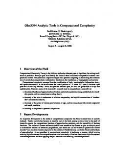
The objective of this paper is to present the recent progress in the R&D neutronics efforts spent in the EU to support the development of the HCLL and HCPB breeder blankets. The focus is on the neutronic design activities performed in the frame of the European DEMO reactor study and the validation effort on neutronics TBM mock-up experiments. Dedicated computational tools, developed as part of the R&D neutronics effort, are being applied for the nuclear design analyses as well as the computational analyses of the experiments. 2. Neutronic Design Efforts A novel methodological approach was developed and applied for the neutronics analyses of the European DEMO Conceptual Study [9]. A central element of the approach was the use of the geometry conversion software tool McCad [10] which enables the automatic generation of a Monte Carlo geometry model for the neutronics calculations from available CAD geometry data. In this way consistency between neutronics and design models was ensured, and modifications of the neutronics reactor model such as the replacement of blanket modules of different kinds could be easily accomplished. The neutronic design analyses performed for the DEMO Conceptual Study, comprised the following steps: (i) Monte Carlo based pre-analyses for the reactor shield dimensioning, (ii) generation of a generic CAD DEMO model suitable for the integration of blanket modules, (iii) conversion of the CAD model to the MCNP [11] geometry to provide a generic DEMO neutronics model, (iv) integration of HCLL and HCPB blanket modules based on available CAD models, (v) nuclear analyses using MCNP to verify and optimise the nuclear performance of the two DEMO variants in terms of the shielding efficiency and the Tritium breeding capability. 2.1 Pre-analyses fort the Shield Dimensioning Pre-analyses were performed on the basis of a provisional set of DEMO reactor parameters derived from plant model AB of the European Power Plant Conceptual Study (PPCS) [12] employing the HCLL blanket. The main objective of the pre-analyses was to determine the minimum shield thickness required to ensure sufficient protection of the super-conducting magnet (TF-coil) at the inboard side of the DEMO plant. The shielding calculations were performed with the Monte Carlo code MCNP [11] using the PPCS AB geometry model with a radial inboard build modified according to the provisional DEMO parameters. Fig. 1 shows the radial profiles obtained for the fast, total and the low energy neutron flux density from the first wall down to the TF-coil. It is noted that a strong attenuation is provided only by the shield and the vacuum vessel due to the chosen material compositions and dimensions. The shield reduces the fast neutron flux by about four orders of magnitude, i. e. one order per magnitude per 10 cm, and the vacuum vessel by about three orders of magnitude, i. e. one order of magnitude across ≅13 cm. The maximum fast neutron fluence to the Cu copper stabilizer operation turned out to be the strictest radiation design limit for the superconducting coils [9]. Assuming a warming-up of the TF coil after 5 full power year, the fast neutron flux density must be less than ≅ 1·109 cm2 -1 s . This can be accomplished by reducing the radial thicknesses of the shield and the vacuum vessel the inboard side to 30 and 35 cm, respectively.
3
16
10
low (0.1 MeV) total
15
14
10
2
13
Vacuum vessel
10
12
11
10
10
10
9
10
8
10
Shield
FW + Breeder zone
Manifold
10
TFC
Neutron flux density [1/cm s]
10
7
10
6
10
5
10
0
20
40
60
80
100
120
140
160
180
200
Radial distance from FW [cm]
Fig. 1: Radial profiles of the neutron flux densities across the inboard mid-plane of the HCLL power reactor. 2.2 DEMO Reactor Model Generation A generic CAD model of a 22.5° torus sector constructed at EFDA, CSU Garching, on the basis of the provisional DEMO data and the results of the neutronics pre-analysis, formed the geometry data input to McCad. Prior to the conversion step, the CAD model was adapted to the requirements for the neutronics calculations by removing non-analytical surfaces which are not accepted by MCNP, and repairing modelling errors such as gaps and overlaps. After the successful conversion step, the model was completed by voids and output in the standard MCNP syntax. The generic neutronics DEMO model did not include blanket modules. For the integration of blanket modules, a poloidal segmentation of the boxes with 7 outboard and 6 inboard modules was introduced according to the engineering designs developed for HCLL and HCPB power reactors. The first wall is formed by plane segments and follows as close as possible the (continuous) first wall contour of the generic DEMO model. In toroidal direction, a 11.25° sector was assumed with a segmentation of 1 and ½ blanket modules both at the inboard and outboards side. The blanket modules were modeled with CATIA V5 on the basis of available engineering designs for a single module. These designs are based to a large extent on the HCLL and HCPB blanket concepts developed in the frame of the PPCS study [13, 14]. Fig. 2 shows the DEMO reactor model with integrated HCLL blanket modules as generated with CATIA V5 and converted into an MCNP model by McCad.
4
Fig. 2: DEMO torus sector model (11.25°) with integrated HCLL blanket modules for neutronics analyses: CAD model generated with CATIA V5 (left) and MCNP model converted and visualised by McCad (right) 2.3 Nuclear Performance Analyses The main objectives of the nuclear analyses were to prove tritium self-sufficiency within a specified margin for the HCLL and HCPB DEMO variants, and, further, to provide the nuclear power production data required for assessing the balance of power of the DEMO plant. Three-dimensional Monte Carlo calculations were performed to this end with MCNP and nuclear cross-sections from the FENDL-2 data library [15]. The global Tritium Breeding Ratio (TBR) was shown to amount to 1.08 and 1.09 for the HCPB and the HCLL Demo variant, respectively, assuming the standard 6Li enrichment 40 at% for the HCPB and 90 at% for the HCLL blanket. This is considered sufficient to ensure Tritium self-sufficiency when taking into account uncertainties involved in the TBRcalculations due to uncertainties of the nuclear data, the effect of the 6Li burn-up during the blanket lifetime, the presence of ports without breeder blanket as well as Tritium losses in the fuel cycle. It was thus concluded that both the HCLL and the HCPB variants can satisfy the requirements for a sufficient shielding and Tritium breeding performance. 3. Neutronic Validation Effort The current validation effort in the EU aims at checking and validating the capability of the neutronic tools and data to predict the Tritium production and other nuclear responses of interest in the TBM. To this end, mock-ups of the HCPB and HCLL Test Blanket Modules are irradiated at the Frascati Neutron Generator (FNG). The Tritium generated during the irradiation in a series of Li2CO3 pellets of the mock-up is measured and compared to calculations using the standard simulation tools, e. g. the MCNP code, and up-to-date nuclear data libraries such as JEFF-3.1 (EU) and FENDL-2.1 (IAEA). In addition,
5
sensitivity/uncertainty analyses are performed to assess the uncertainties of the Tritium generation and trace down discrepancies to specific nuclides, reactions and energy ranges. 3.1 HCPB TBM Mock-up Experiment The first validation experiment of this kind was performed on a neutronics TBM mock-up of the HCPB breeder blanket [16]. The mock-up replicated the main characteristics of a breeder insert of the HCPB TBM in ITER consisting of a stainless steel box filled by alternating layers of breeder material (Li2CO3) and neutron multiplier (Be). The Tritium generated in the Li2CO3 pellets during irradiation was shown to be underestimated by 5 to 10% on average independent on the nuclear data used. The obtained results indicate that design calculations for the Tritium breeding ratio (TBR) of fusion power reactors employing a HCPB type breeder blanket are conservative. Thus an additional TBR margin is provided which allows compensating for potential other uncertainties. A Monte Carlo based sensitivity/uncertainty analysis performed by the MCSEN code yielded uncertainties in the range of 4% dominated by the cross-section uncertainties of 9Be [17]. 3.2 HCLL TBM Mock-up Experiment A follow-up experiment on a neutronics mock-up of the HCLL TBM is currently under preparation [18]. Computational pre-analyses were performed to optimise the design of the mock-up configuration for the planned measurements and to provide first assessments of the uncertainties for the calculated Tritium production. In addition, advanced techniques are being developed to measure the Tritium production by means of Thermo-luminescence and Lithium diamond detectors. The neutronic HCLL blanket mock-up consists of alternate layers of solid Pb-Li bricks and steel plates madel of the RAFM steel Eurofer-97. Two thin layers and a reflector of Polyethylene (PE) are introduced inside the mock-up and its back, respectively, to simulate the effect of neutron reflecting materials surrounding the TBM module in ITER, see Fig. 3. Pb-Li bricks Polyethylene back reflector Neutron generator
Polyethylene internal layers Eurofer steel plates
air
Li2CO3 pellet stacks
Fig. 3: HCLL TBM mock-up (MCNP model, vertical cut) showing the Pb-Li bricks, the Eurofer steel plates, the polyethylene layers and one row of Li2CO3 pellet stacks.
6
The computational pre-analyses were performed with the objective to optimise the HCLL mock-up in such as way that the essential nuclear features of the HCLL TBM in ITER can be represented in the experiment. To this end, Monte Carlo calculations were performed with the MCNP5 code [11] and nuclear cross-section data from the FENDL-2.1 [15] nuclear data library for both the HCLL TBM in ITER and the TBM mock-up. Neutron flux spectra and Tritium production distributions were compared for two detector positions located at 5.5 and 30.1 cm, respectively, from the front surface. For the bare “look-alike” HCLL mock-up assembly, the neutron spectra were shown to be significantly harder than in the HCLL TBM in ITER. This is mainly due to the fact that the TBM in ITER is surrounded by shield modules made of a steel/water mixture thus resulting in a comparatively soft spectrum impinging onto the TBM. The bare HCLL mock-up assembly, on the other hand, does not contain any neutron moderator. In addition, it does not contain a strong neutron absorber since the lithium of the Pb-Li alloy is not enriched in 6Li. Together with the high neutron scattering power of lead this results in a rather high neutron leakage and a comparatively hard neutron spectrum. The Tritium generation in the mock-up therefore mainly takes places in the high energy range above 0.1 MeV while in the TBM a significant amount is produced at low energies. A better simulation of the spectral TBM Tritium distribution is achieved by applying additional PE shields, both at the back of the mock-up assembly and as thin horizontal layers in the centre of the block. This measure softens the neutron flux spectra and enhances the contribution of the Tritium produced by 6Li.
1 0,9 0,8 0,7
Li2CO3 6
natural Li
0,6 0,5 0,4 0,3
0,2
0,1 1E-7
HCLL (2.8 cm) HCLL (7.0 cm) HCLL (11.2 cm) HCLL (28.0 cm) ITER TBM front (5 cm) ITER TBM rear (29 cm) 1E-6
1E-5
1E-4
1E-3
0,01
Energy [MeV]
0,1
1
10
Cumulative Tritium Production, norm.
Cumulative Tritium Production, norm.
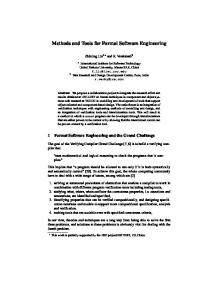
Fig. 4 shows the cumulative normalized Tritium production for the mock-up configuration with two PE layers inside and a PE reflector attached to the back of the assembly. It can be observed that the moderation power of the HCLL mock-up assembly is still weak compared to the ITER TBM configuration. For the Li2CO3 pellets with natural Lithium, the 7Li contribution is significant in the first two positions of the mock-up assembly. Only at larger depths the spectral Tritium production distribution of the mock-up and the ITER TBM configuration agree satisfactorily (Fig. 4, left). A better adaptation to the TBM distributions can be achieved, however, by using pellets enriched in 6Li (Fig. 4, right). 1 0,9 0,8 0,7
Li-6 enriched
0,6 0,5 0,4 0,3
0,2 HCLL (2.8 cm) HCLL (7.0 cm) HCLL (11.2 cm) ITER TBM front (5 cm) ITER TBM rear (29 cm) 0,1 1E-7
1E-6
1E-5
1E-4
1E-3
0,01
0,1
1
10
Energy [MeV]
Fig. 4: Cumulative Tritium production rates in the HCLL mock-up compared to front and rear positions in the ITER TBM. The pellet detectors consist of Li2CO3 with natural Lithium (left figure) and enriched Lithium (90 at% 6Li, right figure). First assessments of the cross section sensitivities and uncertainties were performed in a deterministic approach using SUSD3D [19] with the direct and adjoint angular moment fluxes
7
provided by the discrete ordinates code DORT [20] in a simplified two-dimensional geometry representation. The sensitivities of the Tritium production rate to the lead cross sections were shown to be relatively low, less than 1% per 1% of change in the cross sections with the elastic scattering being the most sensitive reaction. The overall uncertainty which is in the range of 1 to 3 % (depending on the co-variance data used) [18] is dominated, however, by the (n,2n) and (n,3n) reactions of the lead isotopes since the precision of the elastic scattering cross-section is rather high. 4. Monte Carlo based sensitivity/uncertainty calculations One of the important objectives of the nuclear testing of the TBM in ITER will be to check the capability of the neutronic codes and data to predict nuclear responses such as the tritium production, the neutron flux spectra, and the nuclear heating within sufficient accuracy. This requires the capability for assessing the uncertainties of the nuclear responses in the real three-dimensional reactor configuration. The Monte Carlo based calculation of uncertainties of nuclear responses in the TBM in ITER requires in addition the capability to calculate sensitivities for responses by the track length estimator. Suitable algorithms based on the differential operator method were developed to this end and implemented in a local version of the Monte Carlo code MCNP, called MCSEN [21]. This approach enables the efficient calculation of sensitivities for neutron fluxes and nuclear responses such as reaction rates in a geometry cell of an arbitrary three-dimensional geometry. Thus the real TBM model can be employed in the sensitivity calculations in the three-dimensional tokamak configuration as used routinely for the design calculations. The first MCSEN test application using the track length estimator sensitivities was on the sensitivity/uncertainty analysis of the HCPB neutronics mock-up experiment described above, i. e. for a comparatively simple geometrical configuration [17]. The first test application for a complex tokamak configuration was recently performed for the HCPB TBM in ITER [22]. Sensitivity profiles and integrated sensitivities were calculated for the total Tritium production in the TBM by using the track length estimator approach of MCSEN. The associated uncertainties of the Tritium production due to nuclear data uncertainties were assessed by making use of available co-variance data from different sources. The major contribution to the sensitivities was shown to come from the materials contained in the TBM, in particular the Beryllium neutron multiplier and the breeder ceramics constituents 6Li and 16 O. With the calculated sensitivity profiles and the available co-variance data, the crosssection induced uncertainties of the Tritium production have been assessed at a level of 2.8 %. 5. Conclusions The recent progress in the R&D neutronics efforts spent in the EU to support the development of the HCLL and HCPB breeder blankets has been presented. These efforts include neutronic design activities performed in the frame of the European DEMO reactor study, validation efforts by means of neutronics TBM mock-up experiments using 14 MeV neutron generators, and the development of dedicated tool computational tools such as the geometry conversion software McCad, and the MCSEN code for Monte Carlo based calculations of sensitivities & uncertainties. The supporting validation effort was devoted to the capability of the neutronic tools and data to predict the Tritium production and other nuclear responses of interest in neutronics mock-up experiments. Such an experiment has been already conducted on a HCPB mock-up while another on a HCLL mock-up is under preparation.
8
Acknowledgement This work, supported by the European Communities under contracts of Associations with EURATOM, was carried out within the framework of the European Fusion Development Agreement. The views and opinions expressed herein do not necessarily reflect those of the European Commission.
References: [1] ANDREANI, R., DIEGELE, E., et al, “Overview of the EU fusion nuclear technologies development and essential elements on the way to DEMO”, Fus. Eng. Des. 81(2006), 25-32. [2] FISCHER, U., BATISTONI, P. et al, , EU Blanket Design Activities and Neutronics Support Efforts, Fus. Sci. Techn. 47 (2005), 1052 -1059. [3] MEYDER, R., BOCCACCINI, L. V., et al., “New modular concept for the helium cooled pebble bed test blanket module for ITER”, Fus. Eng. Design 75–79(2005), 795–799. [4] LI PUMA, A., et al, “Breeding blanket design and systems integration for a helium-cooled lithium–lead fusion power plant”, Fus. Eng. Des. 81 (2006), 469-476. [5] MAISONNIER, D., “European DEMO design strategy”, Fus. Eng. Des. (2008), in print [6] L.V. BOCCACCINI, SALAVY, J.-F., et al., “The European test blanket module systems: Design and integration in ITER”, Fus. Eng. Des. 81(2006), 407-414. [7] FISCHER, U.; BATISTONI, P., et al., “Neutronics and nuclear data for fusion technology”, 21st IAEA Fus. En. Conf., Chengdu, China, Oct. 16-21, 2006, ISBN 92-0-100907-0, ISSN 1991-2374. [8] FISCHER, U., “Computational methods, tools, and data for nuclear analyses of fusion technology systems”, Int.. Conf. Nuclear Energy for New Europe, Portoroz, Slovenia, September 18-21, 2006 [9] FISCHER, U., GROSSE. D., PERESLAVTSEV, P., et al, “Neutronic design analyses of fusion power reactors”, 25th Symp. Fusion Technology, September 15-19, 2008, Rostock, Germany [10] TSIGE-TAMIRAT, H., FISCHER, U., “CAD Interface for Monte Carlo Particle Transport Codes”, Proc.of the Monte Carlo Conf., Chattanooga, April 17-21, 2005 LaGrange Park, Ill.: [11] X-5 MONTE CARLO TEAM, “MCNP - A General Monte Carlo N-Particle Transport Code Overview and Theory (Version 5, Vol. I)”, Report LA-UR-03-1987, 24 April 2003 [12] SARDAIN, P. et al, “The European power plant conceptual study: Helium-cooled lithium–lead reactor concept”, Fus. Eng. Des 81 (2006), 2673–2678. [13] HERMSMEYER, S., et al, “Revision of the EU Helium cooled pebble bed blanket for DEMO”, 20th IEEE/NPSS Symp. on Fus. Eng. (SOFE), San Diego, USA, October 14- 17, 2003. [14] LI PUMA, A., et al, “Breeding blanket design and systems integration for a helium-cooled lithium–lead fusion power plant”, Fus. Eng. Des. 81 (2006), 469-476 [15] ALDAMA, D. L., TRKOV, A., “FENDL-2.1: Update of an evaluated nuclear data library for fusion applications”, Report INDC(NDS)-467, December 2004 [16] BATISTONI, P., et al., “Neutronics experiment on a HCPB breeder blanket mock-up”, Fus. Eng. and Des. 82 (2007), 2095-2104 [17] LEICHTLE, D., FISCHER, U., KODELI, I., PEREL, R. L. et al, “Sensitivity and Uncertainty Analyses of the HCPB Blanket Mock-up Experiment”, Fus. Eng. Des. 82 (2007), 2406–2412. [18] BATISTONI, P., et al., “Design optimisation and measuring techniques for the neutronics experiment on a HCLL mock-up”, 25th Symp. Fus. Techn., Sept. 15-19, 2008, Rostock, Germany [19] KODELI, I., “Multidimensional Deterministic Nuclear Data Sensitivity and Uncertainty Code System, Method and Application", Nucl. Sci. Eng., 138 (2001), pp. 45-66 [20] RHOADES, W. A., et al, “DOORS 3.2, One-, Two-, Three-Dimensional Discrete Ordinates Neutron/Photon Transport Code System”, CCC-650, RSICC, ORNL (1998). [21] PEREL, R. L:, WAGSCHAL, J. J., YEIVIN, Y., “Monte Carlo Calculation of Point-Detector Sensitivities to Material Parameters,” Nucl. Sci. Eng. 124, 197-209 (1996). [22] FISCHER, U., LEICHTLE, D., PEREL, R. L., “Monte Carlo based sensitivity and uncertainty analysis of the HCPB Test Blanket Module in ITER”, Fus. Eng. Des. 81 (2008), in print.