methodology for model-based development of automotive control software based on custom, problem- specific design notations with an explicit formal.
05AE-268
AutoMoDe – Notations, Methods, and Tools for Model-Based Development of Automotive Software Andreas Bauer, Manfred Broy, Jan Romberg, Bernhard Schätz Institut für Informatik, Technische Universität München
Peter Braun Validas AG
Ulrich Freund, Nuria Mata ETAS Engineering Tools GmbH
Robert Sandner BMW AG
Dirk Ziegenbein Robert Bosch GmbH Copyright © 2005 SAE International
ABSTRACT
1.1 BACKGROUND
This paper describes the first results from the AutoMoDe project (Automotive Model-based Development), where an integrated methodology for model-based development of automotive control software is being developed. The results presented include a number of problem-oriented graphical notations, based on a formally defined operational model, which are associated with system views for various degrees of abstraction. It is shown how the approach can be used for partitioning comprehensive system designs for subsequent implementation-related tasks. Recent experiences from a case study of an engine management system, specific issues related to reengineering, and the current status of CASE-tool support are also presented.
Current challenges in automotive control systems design include quickly rising system complexity across all domains, tight time-to-market constraints (necessitating better predictability for design efforts such as integration), the transition from realization of control logic in mechanical/electrical systems to software implementations, and heterogeneous design chains crossing several technical disciplines and organizations or companies.
1. INTRODUCTION AutoMoDe is a joint research project consisting of members of the Software & Systems Engineering group at the Technische Universität München, Validas AG, ETAS GmbH, Robert Bosch GmbH, and BMW AG. The overall goal of the project is to develop an integrated methodology for model-based development of automotive control software based on custom, problemspecific design notations with an explicit formal foundation. A series of prototypical tools is being developed which builds on the existing AutoFOCUS [HSE97] framework in order to illustrate the key elements of the methodology presented.
Traditionally, the focus of embedded software engineering has been on the later and thus more detailed abstraction levels, which deal mostly with implementation-related issues. More abstract system descriptions typically take a back seat in the design process because they lack suitable notations, methodologies, and integration between abstraction layers. However, working at higher levels of abstraction will be a key factor in tackling the prevalent complexity issues in automotive software engineering, and in catering to different stakeholders in the design chain. For these reasons, the organization of design artefacts along abstraction layers tailored for different stakeholders and different phases has been identified as a possible remedy in the past [BBRS03][Thu03]. A related method should then provide support for easy transitions between layers, e.g. for restructuring designs. Notations and underlying models, such as notations for architectural and behavioural design, should be well-integrated.
Consequently, AutoMoDe aims to address the obvious need to organize such artefacts along various abstract levels, tailored for different stakeholders and phases in the overall systems development process. Additionally, transitions between abstraction levels, like restructuring operations, are supported by the accompanying tools. Exchanging design information in a heterogeneous setting is aided by well-established, intuitive, and unambiguous notations for design artefacts. The AutoMoDe tools aim to provide for such support with formally founded notations, with powerful consistency checks suited to the different abstraction levels, and by providing the ability to validate a design’s behavior with built-in simulators. 1.2 OVERVIEW Section 2 of the paper introduces the operational model of AutoFOCUS designs, which are based on a formally defined system model using explicit data-flow and discrete-time semantics. The accompanying tool support facilitates early system validation through simulation and verification capabilities, as well as powerful consistency checks. In Section 3, we detail the graphical representation of AutoMoDe designs, which are specified using a number of different views for differently abstract system levels – each of which targets specific aspects of the design of automotive control systems. Section 4 explains the results and experiences gained during a reengineering case study using the AutoMoDe approach and tool prototypes. The conclusions of this paper are summarized in Section 5, which also gives an outlook and discusses future activities. 1.3 RELATED WORK In the related research project Automotive [BBRS03] BMW, Bosch, ETAS, Telelogic and Technische Universität München have developed a model-based language and method for developing automotive control software. To achieve practicable usability, the method was based upon relevant and commercially available tools like ASCET, DOORS and the UML Suite. The Automotive Modeling Language (AML) is based on a definition of distinct abstraction levels similar to the AutoMoDe abstraction levels presented in this paper, a concrete syntax based on the UML 1.x and the ASCET notations for structural system descriptions, and an easily usable concept for variants and configurations. AutoMoDe addresses two inadequacies in Automotive’s results: firstly, instead of UML 1.x, AutoMoDe uses the AutoFOCUS [HSE97] notation with an explicit concept of components and their composition for the description of the structures of embedded systems. AutoFOCUS is also very closely related to selected UML 2.0 concepts, so possible standard conformance in the future is not regarded as critical. Secondly, beyond the purely structural designs considered in Automotive, AutoMoDe is also concerned with behavioral aspects.
EAST-EEA: The European automotive industry started this project running under the ITEA banner in 2001. The project was finished in July 2004. An Architecture Description language, the so-called EAST-ADL, has been defined, along with a definition of a domain-specific middleware [Thu03]. The EAST-ADL [Fre04] is structured into several abstraction levels by defining the following architectures: • • • • • • •
Vehicle Project (VP) Functional Analysis Architecture (FAA) Functional Design Architecture (FDA) Logical Architecture (LA) Operational Architecture (OA) Hardware Architecture (HA) Technical Architecture (TA)
The vehicle project describes the electronic features of a vehicle and all resulting variants from a customer’s point of view. The structure of electronic features themselves is described by using inputs and outputs in the functional analysis architecture. If necessary, the structure can be reinforced by behavioral models. The functional design architecture is the most abstract description of software structures to be found later in the ECU software implementation. This architecture consists of a functional hierarchy with a focus on typed structures and signal exchange. In addition, it is possible to associate behavior with functions of the hierarchy. However, only elementary functions, i.e. the leafs of a functional hierarchy, can carry behavior to be flexible for the final placement of functions on ECUs. Behavior can be described using finite state machines, difference equations, or plain source code. The logical architecture describes the system on a pure instance level. Instances can be mapped to ECUs and OS tasks while still respecting all timing and memory requirements. ECU properties with their sensors and actuators as well as the bus systems are described in the hardware architecture. Configurable basic software components for the ECUs like OS, HAL and the EAST middleware form the technical architecture, while the operational architecture describes the running system. The latter is conceived by mapping the instances of the logical architecture to ECUs, OS tasks and bus messages and then by applying code generation of the application software and by configuring the basic software. The use of explicit operational modes for decomposition has also been brought forward by other authors, e.g. [MR98]. In addition to the idea of using explicit notations for operational modes, our approach employs such mode representations across several levels of abstraction, especially for coarse-grained structuring of systems, and in particular investigates transformations between different mode representations suited for different abstraction levels. The concept of expressing frequencies and event patterns as Boolean expressions (clocks), and the idea of providing a type system for such clocks, originates
from the field of synchronous programming languages [IEE91].
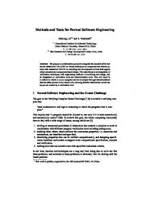
2. OPERATIONAL MODEL AutoFOCUS uses a message-based, discrete-time communication scheme as its core semantic model. AutoFOCUS designs are built from networks of components or blocks (drawn graphically as a rectangle) exchanging messages with each other and with the environment via explicit interfaces (drawn as small circles) and connectors between interfaces. Messages are time stamped with respect to a global, discrete time base. This computational model supports a high degree of modularity by making component interfaces complete and explicit. It also provides a reduced degree of complexity: Because the discrete time base abstracts from implementation details such as detailed timing or communication mechanisms, the use of timing information below the chosen granularity of observable discrete clock ticks is avoided. Examples for such detailed assumptions include the ordering of message arrivals within one time slot, or duration and delays of transfer. Real-time intervals of the implementation are therefore abstracted by logical-time intervals. Note that this message-based time-synchronous communication model does cater to both periodic and sporadic communication as required for a mixed modeling of time-triggered and event-triggered behavior. As shown in Figure 1, each channel in the abstract model either holds a message represented by an explicit value or the “ ” (“tick”) value indicating the absence of a message. Thus modeling of event-triggered behavior is naturally covered by the AutoFOCUS notation by reacting explicitly depending on the presence (or absence) of a message. T1C:LockCommand
T4S:LockStatus FZG_V:Voltage
T2C:LockCommand DoorLockControl
CRSH:CrashStatus
FZG_V
T3C:LockCommand T4C:LockCommand
t
t+1
t+2
20
√
23
Figure 1: Message-based, time-synchronous communication.
3. ABSTRACTION LEVELS AND VIEWS The different system abstractions and their supported views on the system (see Fig. 2) are central to the model-based approach of AutoMoDe. The system abstractions chosen are similar to those defined in [Thu03] (see also Sec. 1.3), but are adapted to match the model-based AutoMoDe development process. The abstraction levels and the corresponding use of the AutoFOCUS notations are introduced in the following.
Figure 2: AutoMoDe abstraction levels.
3.1 FUNCTIONAL ANALYSIS ARCHITECTURE The Functional Analysis Architecture (FAA) is the most abstract level considered in AutoMoDe. The FAA provides a system-level abstraction representing the vehicle functionalities to be implemented in either hardware or software. Use Cases, Feature Tree and Hierarchy Diagrams Today a vehicle may have more than 2,500 software based functions. Typically, it is up to the requirements engineer to decide which functions are required and how these should be structured and realized in terms of user interactions. Feature trees and feature hierarchies provide a structural view of these functions. The structuring of feature hierarchies is strictly use case oriented: at each level of the hierarchy, “function families” are structured into subfunctions until atomic functions are reached. We introduce special relationships between functions that indicate dependencies. Functions without dependencies are distinguished explicitly and are required to remain independent. The behavior of atomic functions can be described by using scenarios in terms of interaction diagrams (message sequence charts), or in a more thorough way via state machines. An FAA-level description is typically complete as to the functionalities being considered and the functional dependencies between them. It enables the identification of functional dependencies and potential conflicts
between vehicle functions to be identified, and the validation of functional concepts based on prototypical behavioral descriptions. Means to achieve these goals include rules as well as model simulation. Based on the functional structure and dependencies, rules identify possible conflicts and suggest suitable countermeasures to resolve them. An exemplary rule is the introduction of specific arbitration functionality wherever two vehicle functions access the same actuator. These rules are E/E-architecture-driven and have been developed in the context of the CARTRONIC framework [LTS01]. The simulation also considers the prototypical behavioral descriptions. These descriptions are not optimized for efficient implementation and abstract from details such as concrete data types. System Structure Diagrams The dominating notation used on the FAA level is called System Structure Diagram (SSD). SSDs are used for describing a high-level architectural decomposition of a system, similar to UML 2.0 component diagrams [UML]. SSDs consist of a network of components, shown as rectangles, with statically typed message-passing interfaces (ports), shown as black and white circles. Explicit directed connectors (channels) connect ports and indicate the direction of message flow between components. Components can be either recursively defined by other SSDs, or by a number of specifically suited notations for behavioral description (see Sec. 3.2). On the FAA level, it may be perfectly adequate to leave the detailed behavior unspecified. For an example SSD, see Fig. 3.
3.2 FUNCTIONAL DESIGN ARCHITECTURE The AutoMoDe system abstraction Functional Design Architecture (FDA) is a structurally as well as behaviorally complete description of the software part of the system or a subsystem. The description is in terms of actual software components that can be instantiated in later phases of the development process. In its current version, AutoFOCUS supports classification and instantiation of components through the shared components mechanism, which groups structurally and behaviorally equivalent components without using a concept of an explicit component type or class, such as in UML. Structural or behavioral modifications to one component in the group are automatically propagated to all other components in the group. The general question of whether explicit component types are beneficial for automotive control systems development is the subject of ongoing research. In contrast to FAA-level functionalities, atomic SSD components in the FDA are required to have a welldefined behavior. Behavior specifications of atomic components are allowed in terms of Data Flow Diagrams, which specify algorithms in terms of blocks communicating through data flows, Mode Transition Diagrams, which decompose the component’s behavior into distinct operational modes, or State Transition Diagrams, which specify reactive, event-driven behavior in an automaton-like style. Data Flow Diagrams Data Flow Diagrams (DFD) define an algorithmic computation of a component. Graphically, DFDs are similar to SSDs (see Fig. 4): DFDs are built from individual blocks with ports connected by channels. Typing of ports is dynamic, using type inference properties of operators. A block may be recursively defined by another DFD. The behavior of atomic DFD blocks is given either through a Mode Transition Diagram (MTD), through a State Transition Diagram (STD), or directly through an expression (function) in AutoFOCUS’s base language [HSE97]. For example, block “Minus” in Fig. 4 is defined by the function “a - b”, where “a” and “b” are port identifiers (not shown). It is possible to define adequate block libraries for discrete-time computations with this mechanism.
Figure 3: Example SSD component network on the FAA level.
The component boundaries introduced with SSDs have semantic implications as well – each SSD-level channel introduces a delay in the communication between components. Because of AutoMoDe’s global discretetime semantics, such implicit introduction of delays is a prerequisite for later partitioning with reduced revalidation effort (see Sec. 3.4). Note that SSDs are not unique to the FAA, but will be used throughout this text on other abstract system levels as well (see Sec. 3.2 – 3.3).
Figure 4: Example DFD for a longitudinal momentum controller component.
In contrast to the delayed composition primitives in SSDs, the semantics of DFD composition is “instantaneous”, in the spirit of synchronous languages [IEE91]. In the AutoFOCUS tool, instantaneous
communication primitives are accompanied by a causality check for detecting instantaneous loops. Note that computations “happening at the same time” in FAA-, FDA- or LA-level models are perfectly valid abstractions of sequential, time-consuming computations on the level of the Operational Architecture (OA) if the abstract model’s computations are observed with a delay, such as the delays introduced by SSD composition. The duration of the delay then defines the deadline for the sequential computation on the OA level.
A cluster can be thought of as a “smallest deployable unit” in a software system. Consequently, several clusters may be mapped to a given operating system task on the OA level, but a given cluster will not be split across several tasks.
Mode Transition Diagrams Mode Transition Diagrams (MTDs) are used to represent explicit system modes and alternate behaviors within modes (see Fig. 5). MTDs consist of modes and transitions between modes. Transitions are triggered by certain combinations of messages arriving at the MTD’s component. The behavior of the component within a mode is then defined by a subordinate DFD or SSD associated with the mode. As illustrated by the detailed example in Sec. 4, MTDs provide a valuable means of architectural decomposition specifically suited for embedded control systems.
Figure 6: Example STD for exhaust control of an engine.
Cluster Communication Diagrams
Figure 5: Example MTD for operational modes of an engine.
State Transition Diagrams STDs are extended finite state machines with states and transitions between states (see Fig. 6). STDs are similar to the popular Statecharts notation, but with some syntactic restrictions. Through the restrictions chosen no AND states, no inter-level transitions, restricted preemption primitives - semantic ambiguities allowed by some standard Statecharts dialects [vdBeeck94] are avoided. 3.3 LOGICAL AND TECHNICAL ARCHITECTURE The Logical and Technical Architecture (LA, TA) is the most implementation-oriented abstraction level supported by the AutoMoDe method. FDA-level components are instantiated and grouped into clusters at the LA level. The TA represents hardware and platform components (ECUs, buses, message frames) used to implement the system.
The notation used for top-level definition of the LA structure is called Cluster Communication Diagrams (CCD). Like SSD components, clusters have statically typed interfaces. In contrast to the recursive definition of SSDs and DFDs, CCD clusters must not be defined by other CCDs. On the other hand, hierarchical DFD descriptions are perfectly adequate for clusters. The type system at the LA level is extended by implementation types which capture the more or less platform-related constraints associated with implementation. Signal frequencies and event patterns are required to be explicit on the LA level, but not at the FAA and FDA levels. Signal frequencies and event patterns are represented in the AutoFOCUS notation as clocks: Each message flow in AutoFOCUS is associated with such a clock. The clock for any given flow indicates either the frequency of message exchange (periodic case), or a condition describing the event pattern (aperiodic case). Syntactically, a clock is simply a Boolean expression evaluating to logical “true” whenever a message is present on the clock’s flow. Graphically, clocks may be represented as an element of a channel’s or port’s label, which has the form ::. Clocks are supported within the AutoFOCUS2 tool through by explicit sampling operators (indicated as “w” blocks in the examples) and an inference system, similar to type inference in programming languages.
The graphical representation of CCDs is identical to DFDs (see Fig. 7). In particular, the half-shaded diamonds indicate explicit delay operators.
Figure 7: Example CCD for engine controller (simplified).
3.4 TRANSITIONS BETWEEN ABSTRACTION LEVELS Transition FDA->LA To make the transition from an SSD representation on the FDA level to an LA-level CCD, some of the topmost SSD hierarchy may be dissolved in favor of a flat CCD representation. Clusters can then be defined in terms of (hierarchical) DFDs, MTDs, and STDs. In addition, abstract data types such as “int” are typically mapped to an implementation, e.g. “int8” or “int16”. Similarly, a floating-point message on the FDA level may be mapped to a fixed-point or integer message on the LA level. In order to represent high-level MTDs as a network of clusters on the LA level, the AutoFOCUS2 tool prototype provides a built-in utility to transform an MTD into a semantically equivalent, partitionable dataflow model. Partitioning in AutoMoDe involves grouping an FDA-level description into clusters on the LA level. Because of the many design tradeoffs involved, we expect that this task can be automated chiefly on the level of elementary transformations, while essential design decisions are left to the engineer. As an example, the following two heuristics are supported by elementary AutoMoDe refactoring steps: (1) Partitioning along the SSD structure decomposition of FDA-level components. This strategy provides a clear one-to-one correspondence between FDA and LA descriptions. (2) Partitioning according to common signal and communication frequencies. This strategy may be preferable for technical reasons, e.g. reduced number of control flow (if-then-else) statements, reduced execution time jitter, better utilization of resources.
With regard to required delays and dedicated conditions concerning the syntactic and semantic validity of CCDs, clusters may depend on the characteristics of a given Technical Architecture. As an example, consider an OSEK-conforming operating system as a target platform, with inter-task communication between tasks using data integrity mechanisms [PMS+95] and fixed-priority, preemptive scheduling. In this framework, communication from “slower” clusters to a “faster” cluster necessitates the introduction of at least one delay operator in the direction of data flow. On the other hand, communication in the opposite direction (“fast” to “slow” cluster communication) does not require introduction of delays in the CCD. Note that implementation-driven introduction of delays may significantly alter a system’s behavior, depending on the nature of an application. Therefore, early introduction of delays from the top down between SSD components on the FAA and FDA levels is made with the intention of avoiding a costly revalidation of models after the transition to the (more implementation-driven) LA/TA level.
4. REENGINEERING The aforementioned concepts and descriptions (see Sec. 2 – 4) have been applied to an extensive automotive case study where the engine controller for a four-stroke gasoline engine was modeled. Originally, this case study [Bea99] was provided in terms of a detailed ASCET [ETAS] design and has been reengineered in important parts using an early AutoMoDe tool prototype, AutoFocus (see Sec. 5), along with the related notations and underlying semantics. 4.1 OPERATING MODES Compared to ASCET, AutoFOCUS provides a richer set of control flow primitives. As it turns out, the AutoMoDe concept of modes and MTDs can capture and encapsulate implicit operation modes of the original ASCET design especially well. What is more, implicit modes of ASCET processes can be made explicit to the developer by using MTDs rather than control flow operators such as if-then-else (see Fig. 8). In other words, MTDs support a comprehensible design not only because they hide parts of a complex computation in hierarchical components, but also because they make clear which mode a certain part of the system is in that is actually being modeled by the user at any time. The latter is an especially strong argument for the use of modes from a methodological point of view, since they prevent potentially conflicting control flow statements based on a wrong evaluation of Boolean variables, or flags. For example, the purpose of the component named “ThrottleRateOfChange” is to determine the rate at which the throttle valve position changes, not only depending on its current and the desired position, but also
depending on very specific states of the entire engine (control management). Other approaches such as MATLAB Simulink or ASCET would typically use a separate block for handling the control logic of the engine modes. This control logic block would then communicate a large number of flags and control values to the remaining blocks of the subsystem to influence their behavior based on the current operating mode. The control values, however, are evaluated inside the control logic block as well as in the respective subsystems, which may yield (deadlock-like) conflicts due to subtle inconsistencies in the control flow.
It is then up to the systems engineer to decide whether MTDs should capture a more data-oriented or controlflow oriented view of the system. A purely dataflow-oriented approach to MTDs would result in MTDs at very low levels of abstraction inside isolated DFD blocks. This essentially results in a high number of single MTDs and yields a greater effort in constructing a consistent global state model. On the other hand, the purely control flow oriented way of using MTDs will impose only a small number of MTDs in top-level components, which then more or less represent the global state model of the system. The downside of this approach, however, is there is not much modularity and greater redundancy in the model, since a lot of the underlying computations would be made in more than one mode.
5. TOOL SUPPORT
Figure 8: AutoFocus component, ThrottleRateOfChange, with an embedded MTD which consists of two states: “FuelEnabled” and “CrankingOverrun”.
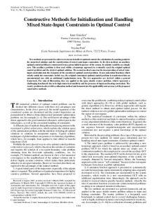
The goal is to validate all concepts developed in AutoMoDe by at least some prototypical tools. An enhanced tool for specifications used in AutoMoDe is currently being developed called AutoFOCUS2, which is based on the existing AutoFOCUS framework. The tool includes a generic logic programming language interpreter for checking and manipulating specifications. Fig. 9 shows AutoFOCUS2’s logic language interpreter with the model browser and two editor windows. The consistency check mechanism also includes rules to identify possible violations of consistency conditions.
Modeling a subsystem such as “ThrottleRateOfChange” with MTDs and modes, on the other hand, separates the component into distinctive modes – even using distinctive name tags for those – which are modeled and viewed separately in the tool depending on the respective engine state (see Fig. 8). That is, an MTD design treats modes as first-class citizens while purely control-flow oriented modelling usually lacks the concept of mode representation. In the case of ThrottleRateOfChange, the top-level MTD is attached to two separate DFD descriptions which, when executed, each consume incoming signals, if the mode being dealt with is currently active. Clearly, the calculation of the throttle position change rate is different in cranking mode compared to “normal” engine operation while driving. Consequently, the incoming Boolean flags for mode control can also be thought of as DFD trigger signals. 4.2 DATA- VS. CONTROL-FLOW-ORIENTED DESIGN On the other hand, MTDs also provide a great amount of flexibility, since they do not impose any restrictions on the level of abstraction where modes can be used. Hence, MTDs may appear on the structural level inside SSD components, or in the FDA and LA/TA inside DFD blocks. Additionally, MTDs may be hierarchic, meaning one single mode may consist of further MTDs with additional modes.
Figure 9: Screenshot AutoFocus2 tool.
The existing AutoFocus tool [HSE97] and the AutoFOCUS2 tool include further extensions, in addition to basic functionalities like simulation or code generation. A concept to describe the implementation of data types based on the experiences gained from ASCET was developed and included into the AutoFOCUS framework. This means that an abstract number data type like integer or real could be used in early specifications.
These data types will be refined in later phases, for example into a 16-bit integer or a standard fixed or floating point representation. AutoFOCUS supports simulation and type consistency mechanisms for abstract data types as well as implementation data types, and even for specifications using a mix of both. The model often has to be re-factored when automotive control software is designed. For example, a component within one component hierarchy has to be moved into another hierarchy. Typical re-factorings are defined and implemented in AutoMoDe. For this reason the AutoFOCUS framework was extended by a generic language to specify model transformations. A central part of the AutoMoDe tool prototype is the connection with ASCET. We show the practical applicability by integrating a currently used tool for automotive control software design. On the one hand, AutoMoDe models should be automatically transformed into ASCET models so that it is possible to further refine these models to generate code for different embedded platforms. On the other hand, ASCET models are converted into AutoMoDe models to support reengineering of existing models. Naturally, reengineering is the only tool supported, but it generally does not automatically produce reasonable results without user interaction. The integration with ASCET described here is currently ongoing research.
6. CONCLUSION This paper has presented some of the early results of the AutoMoDe project, including a definition of abstraction layers, some support, methodically motivated transitions between layers, the graphical notations supported by AutoFOCUS tools, a case study from the engine management domain, and the status of tool support for AutoMoDe. The complex relationships between single design artefacts of a typical automotive software design call for a rich set of possible structuring relations between artefacts. The AutoMoDe domain model currently lacks some of these necessary relationships, such as a mechanism for component typing, or for describing product variants. Extensions of the AutoMoDe domain model with simple typing and variant mechanisms, similar to the results of the Automotive project [BBRS03], are envisioned for the near future.
implementation overhead. This topic will also be a subject of further investigation.
REFERENCES 1.
2.
3.
4.
5.
6. 7.
8.
9.
10.
11.
12. Obviously, the combination of a globally clocked operational model with typical event-triggered communication media such as CAN, which is not tightly synchronized, raises some interesting questions for research. We present in [RB04] a proposal on how to use event-triggered media for firm real-time deployment of globally clocked models with comparatively small
13.
[vdB94] M. v. d. Beeck: Comparison of Statecharts Variants. Third Int’l Symposium on Formal Techniques in Real-Time and Fault-Tolerant Systems (FTRTFT). pp. 128 – 148, 1994 [Bea99] A. J. Beaumont et al.: Automation of ECU Software Development : From Concept to Production Level Code, SAE-Paper 1999-01-1174 [BBRS03] M. v. d. Beeck, P. Braun, M. Rappl and C. Schröder. UML for Real: Design of Embedded Real-Time Systems, Automotive UML. In: Bran Selic, Grant Martin and Luciano Lavagno (eds), Kluwer Academic Publishers, ISBN 1-4020-7501-4, May 2003 [Thu03] Thurner, T., et al., The EAST-EEA project – a middleware based software architecture for networked electronic control units in vehicles. In: Electronic Systems for Vehicles (VDI Berichte 1789), p 545 ff. VDIVerlag, Düsseldorf, 2003. [Fre04] U. Freund et al.: The EAST-ADL: A Joint Effort of the European Automotive Industry to Structure Distributed Automotive Embedded Control Software. 2nd Workshop on Embedded Real-Time Systems, Toulouse 2004. [ETAS] ETAS Engineering Tools GmbH. ASCET User Manual Version 5.0. 2004. ETAS GmbH. [HSE97] F. Huber, B. Schätz, G. Einert. Consistent Graphical Specification of Distributed Systems. FME '97, LNCS 1313, pp. 122 - 141, Springer. [IEE91] Another look at real-time programming. Special Section of the Proceedings of the IEEE, 79(9), September 1991 [Kop93] H. Kopetz. Should Responsive Systems be Event-Triggered or Time-Triggered? IEICE Trans. Inf. & Syst., Vol. E76-D (11), 1993 [LTS01] A. Lapp, P. Torre Flores, J. Schirmer, D. Kraft, W. Hermsen, T. Bertram, J. Petersen. Softwareentwicklung für Steuergeräte im Systemverbund – Von der CARTRONIC-Domänenstruktur zum Steuergerätecode. VDI-Berichte 1646 "Elektronik im Kraftfahrzeug". pp. 249-276. 2001 [MR98] F. Maraninchi and Y. Rémond. Mode-Automata: About Modes and States for Reactive Systems. Proc. European Symposium on Programming, Lisbon, Portugal, 1998 [PMS+95] S. Poledna, T. Mocken, J. Scheimann, T. Beck. ERCOS: An Operating System for Automotive Applications. SAE International Congress, 1995 [RB04] J. Romberg and A. Bauer. Loose Synchronization of Event-Triggered Networks for Distribution of Synchronous Programs. EMSOFT, Pisa, Italy, 2004