Jun 17, 2011 - In the beginning, the development of high dynamic control schemes for ac ... encoderless or speed sensorless ac drives without angular encoder ... milestone that marked the start of the ... parameters (if possible in standstill ... angular position as a train of pulses, ..... as they were reported in [5], have made.
MARIO PACAS
Advanced Control Schemes
Digital Object Identifier 10.1109/MIE.2011.941125
© PHOTODISC
W
o r l d w i d e intensive research in the field of advanced control schemes for ac drives has been performed during the last few years. Parallel efforts in industry and academia aimed the development of sensorless ac drives featuring a dynamic behavior comparable or similar to the drives with mechanical sensor on the shaft. Some of these works and ideas can be found in industrial products and systems available on the market. This article discusses the state of the art of sensorless drives in industrial applications and the reasons that determine the acceptance or refusal of the different solutions on the side of manufacturers of motor drives. In the beginning, the development of high dynamic control schemes for ac drives was characterized by the difficulties in the implementation due to the limited available computing power. The reduction or elimination of necessary sensors was therefore not the main focus. With the advent of modern power electronics, powerful microcontrollers, and digital signal processors (DSPs) as well as enhanced control schemes, this situation changed, and the dream of encoderless or speed sensorless ac drives without angular encoder or tachogenerator, so-called sensorless drives, suitable for a broad variety of demanding applications in general automation is becoming reality. The review of the evolution of the last few decades shows that the sturdy and economical induction machine was always the working horse in manifold
Date of publication: 17 June 2011
16 IEEE INDUSTRIAL ELECTRONICS MAGAZINE n JUNE 2011
1932-4529/11/$26.00&2011IEEE
applications. Also, the availability of frequency converters in the industrial drives for the power range below 50 kW was an interesting and important milestone that marked the start of the technology of variable-speed ac drives (VSDs) with induction machines. Millions of robust and low-cost drives were then equipped with a simple and easy-to-implement volts/hertz openloop control and are still used in simple as well as complex processes of moderate dynamic characteristics and performance. On the other hand, dc drives with better dynamics and featuring a simple sensorless openloop control that uses the estimated speed based on the armature voltage and the field flux instead of a tachosignal were prevailing and could not be immediately substituted by ac drives. Advanced control methods such as field-oriented control and direct torque control (DTC) were the next step toward ac drives possessing excellent dynamics better than that of the dc drives with line-commutated converters. Unfortunately, to achieve the same quality of control, including the region around zero speed in all the proposed control schemes, a mechanical sensor was mandatory. The idea of using the physics of the ac machine for creating a self-sensing drive arose and was the motivation for academia and industry for the huge efforts dedicated to developing schemes without an angular sensor, first for induction machines and later for permanent magnet synchronous machines (PMSMs). In the following, different aspects regarding the state of the art of sensorless drives in industrial applications and the reasons that determine the acceptance or refusal of the different solutions on the side of manufacturers of motor drives are explained and discussed.
General Considerations Industrial Requirements As already stated, in the last few decades, many efforts in academia and industry were dedicated to the development of sensorless drives for induction machines and PMSMs.
However, only recently was a breakthrough achieved, and some of the academic solutions were implemented and used in industrial drives. The hesitant acceptance of the sensorless schemes on the side of manufacturers can be explained with the practical requirements that have to be fulfilled in industrial applications and systems. New control methods can only be accepted if they do not lead to an increase of costs or efforts. Thus, the elimination of the angular sensor is not acceptable if it yields the installation of additional computing power or special sensors, such as voltage sensors. The use of standard induction machines is considered to be one of the advantages of the sensorless schemes. Therefore, any modification in the geometry of the rotor or of the winding has to be carefully considered. Otherwise, the benefits of sensorless systems are diminished. In sensorless schemes, tuning procedures for fitting the models and controllers to the installed electrical motor are required. Today, a main trend in automation is the reduction of installation times and the automatic fitting of parameters (if possible in standstill conditions) is actually expected. Any cumbersome manual setting of values should be reduced to a minimum or circumscribed to special cases. In the higher power range, i.e., medium-voltage drives, the following additional peculiarities have to be taken into account: n a cautious approach because of the excellent experience with standard inverter drives n cumbersome measurement of the dc-link voltage n extreme temperature range n low switching frequency and high current ripple that aggravate the measurement of the stator currents. All these requirements have limited the utilization and have slowed down the introduction of sensorless control schemes in the industrial applications of ac drives. Functions of the Sensor The angular position of the shaft of the machine is obtained by using
rotary encoders, whereas the mechanical velocity can be measured with tachogenerators. These sensors fulfill several functions that should be understood for a thorough assessment of the control schemes with and without sensors. The conventional analog tachogenerator that delivers a voltage proportional to the angular velocity of the shaft is actually still used in dc drives. Despite advantages such as high resolution of the signal and sturdiness of the sensor, tachogenerators have become obsolete in digitalcontrolled ac systems and are therefore not considered in the following. In ac drives with induction machines, an incremental optical or magnetic encoder is usually used, yet the absolute position is not necessary for the control. On the contrary, in drives with synchronous machines (SMs), the absolute position of the rotor is required. For this effect, the resolver has been a popular, sturdy sensor with an acceptable resolution and accuracy. Special calibration procedures for the detection of the absolute position with an incremental encoder and sensors with additional absolute traces of reduced accuracy are also used in industrial drives today for avoiding the expensive absolute angle encoders. In the range of brushless (BL) dc drives, a more simple system is used that delivers the switching instant for the phase currents but still an additional sensor is necessary for the velocity control. It is important to remark that the accuracy and resolution of the shaft encoder determine the performance and the dynamics of the associated velocity or position control and that, for obtaining the velocity, the position has to be differentiated with all implications for its accuracy and resolution. In many applications in general automation or machine building, the motor drives are part of a velocity or position control loop. In such cases, the encoder delivers the actual value of the controlled variable with the dynamics, accuracy, and resolution required by the process or application. In the case of the substitution of
JUNE 2011 n IEEE INDUSTRIAL ELECTRONICS MAGAZINE 17
the encoder by a sensorless scheme, the same characteristics are expected. In recent years, in different production lines such as printing and packaging machines, the aim of the sensorless scheme was to substitute the mechanical components by flexible electronic solutions in so-called mechatronic systems. Some of the basic mechanical functions demanded in such cases concern the angular synchronization of different shafts rotating at different speeds. Thus, the mechanical gear is substituted by an electronic one with the corresponding gear ratio. Digital encoders deliver the angular position as a train of pulses, which is converted to an integer value that allows the exact calculation of gear ratios without any loss of information. In a similar manner, the rotary encoder is used for the calculation of the linear position based on the angular position of the motor shaft, the gear ratio, and the spindle pitch. The encoder is not only required for the purpose of control of speed and position of the drive but also necessary for the complete modeling of the machine, i.e., for the calculation of all state variables based on the measured currents and speed, and moreover for safety reasons such as emergency stop and controlled stop in case of blackout. These special functions are indispensable for avoiding hazards for the operator and preserving the integrity of the process. Such procedures are therefore mandatory for meeting the requirements of standards and regulations. Since encoders are electronic devices able to communicate via field buses, they are also used for the storage of motor-specific data, such as parameters or identifiers, as well as for the exchange of information in actuator–sensor interface networks. The previous considerations are not specific for ac drives; in fact, they apply in machine building and general automation regardless of the type of drive used for the motion control. In the case of ac drives, the angular encoder assumes an additional crucial role, which is one of the reasons for the quest of sensorless
control schemes. The implementation of high-performance control schemes of ac machines (fieldoriented control or DTC) demands the knowledge of the shaft position over the whole speed range, including velocities close to zero for a proper operation. In other words, the position of the shaft is needed for the correct modeling of the ac machine in the different frames of coordinates. Sensorless Drives The previous discussion makes clear that the sensor attached to the shaft, for numerous reasons, can be advantageous or even compulsory, especially in the area of machine building and general automation. Therefore, in the following, the benefits and the motivation for the intensive research in the area of sensorless control are thoroughly analyzed. The push toward sensorless control schemes is often considered to be self-evident. The reduction of costs is indeed one of the most adduced aims for the development of sensorless drives. In reality, not only is the cost of the sensor itself considered, but also the cabling, the appropriate connectors and the interfaces, and all associated expenses have to be considered as well. An evaluation of the life cycle costs of a system should include further aspects such as the crucial issues of the reliability of the whole system. Thus, the encoder reduces the robustness of the electrical machine not only in terms of protection but also regarding electromagnetic compatibility, mechanical oscillations, maximum velocity, and temperature. The installation of an encoder is not always feasible or affordable: hollowshaft motors, high environment temperature, high-speed range, and adverse environmental conditions are some of the reasons that make a sensorless scheme desirable. For historical reasons, many manufacturers of drives make an arbitrary distinction between servos and general-purpose inverters with a volts/ hertz control. Yet, the growing computing power in embedded control
18 IEEE INDUSTRIAL ELECTRONICS MAGAZINE n JUNE 2011
allows the migration from simple volts/hertz inverters toward more sophisticated applications and motion control capability. For this evolution, sensorless schemes offer two important features: the operation with a PMSM and the implementation of a vector control with better dynamics than the simple open-loop control. Sensorless schemes can also be used for emergency operations in case of failure of the sensor. A smooth seamless switching procedure from the operation mode with a sensor to the one without sensors can keep the drive running until a regular inspection or at least a repair allows an emergency stop, which will avoid damages in the machine or the process by increasing the availability of the whole installation. Recently, the promotion of energy saving and higher efficiency policies, e.g., super-premium IE4 class motors, brings an additional new momentum that is influencing the attractiveness of sensorless drives. It is well known that PMSM eases the fulfillment of the new efficiency classes although the substitution of standard squirrelcage induction motors requires the operation of the PMSM on a simple frequency inverter without angular feedback. As will be explained in the following, the sensorless approaches exhibit different dynamic characteristics regarding the speed range. However, the whole speed range, including the velocities close to zero, is not always demanded. A ridethrough capability or the development of full torque at low speed for some time can be sufficient to reach the desired behavior of the machine or the process.
Sensorless Control In the pertinent literature, excellent papers can be found that summarize the state of the art in this area [1], [2]. The aim of this article is not the repetition of the details and the explanation of the theoretical foundations of each method but the elucidation of the principal reasons for acceptance or rejection of each of the
Fundamental Wave Models
Observer EMF Models
Flux Modulation
Exploitation of Anisotropies
Inductances in d and q
….
Slot Asymmetries
Saturation of the Main Path
….
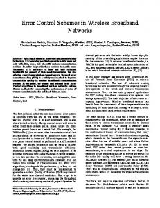
FIGURE 1 – Classification of the sensorless methods.
lines of development in industrial applications. For this effect, in the following, a coarse classification of the known methods is presented that makes no claim to be exhaustive. Figure 1 shows a generally accepted classification of the known methods for sensorless control. In principle, they differ in the model of the machine that is used. The first class of methods uses the classical dynamic equations of the ac machine, whereby a sinusoidal flux density distribution in the air gap is assumed, neglecting space harmonics and other secondary effects. They are called fundamental wave models and are discussed in the following. It is well known that fundamental wave models are not valid at zero stator frequency [2]. The induced voltage in the rotor is then zero, and the system becomes unobservable. Hence, an alternative way for the modeling of the machine is necessary. The second category of methods depicted in Figure 1 exploits the asymmetries of the machine resulting from either the geometry of the design, i.e., anisotropic rotor, or from slotting or from the saturation of the iron path. The other way to overcome the unobservability of the system at zero frequency is the injection of test signals with a frequency different to the fundamental and to perform the calculation of the unknown state variables based on the response of the system to the high-frequency injection. This approach is also used in fundamental wave models by superimposing a low-frequency ac test signal on the stator current of the motor and obtaining in this way a modulation of the flux that allows the operation of the control at low and zero stator frequency [23]–[25].
machine for the detection of unknown variables.
The general structure for both cases is shown in Figure 2: the mathematical model of the machine, i.e., its well-known equations, get as input variables the same values of voltages as the machine and the values of the measured currents of the machine. Based on this information, the unknown variables, including the rotor position and velocity, are computed. Usually for modeling, the reference values of the inverter voltages are used instead of the physical values. Thus, a direct measurement of the terminal voltages is avoided. Nevertheless, some proposals consider the utilization of direct voltage sensing; because of the additional sensors, isolated interfaces, and signal processing, these schemes are mostly discarded in industrial applications. Figure 2 shows an additional channel for the control of an injected signal. This control path is always necessary in those methods that exploit anisotropies of the electrical
L1
L2
Industrial Applications Open-Loop U/f-Control By considering that the highest number of applications of motor drives in industry is found in the sector of fans, blowers, and pumps; for applications in chemicals, oil, and gas; heating, ventilation, and air conditioning (HVAC); water and waste water; and in other industrial processes, it becomes evident that a simple open-loop volts/ hertz control is the most used and most popular sensorless control method for induction machines. Obviously, because of the fact that a highly nonlinear dynamical plant is controlled with an extremely simple strategy, the resulting characteristics are not always satisfactory: it yields a poor torque regulation with a slow dynamic performance and significant limitations such as the
L3
iU
Ud uU
State Variables
iW Model of the Machine
uV uW
Injection Control FIGURE 2 – Principal structure of a sensorless control.
JUNE 2011 n IEEE INDUSTRIAL ELECTRONICS MAGAZINE 19
deficient torque development at low speed. Despite its inherent drawbacks, this scheme offers many advantages that make it the first choice in numerous variable speed applications. The operation of the drive is stable up to the highest speed, the switchover to synchronous or block modulation is simple, and the error in the speed corresponds to the natural slip of the machine, which is more than sufficient for simple processes in industry. Although the poor dynamic behavior is claimed to be the main drawback of the U/f-control, the fact of the lack of torque at low speed forbids its utilization in all cases that demand a stable starting torque. Fortunately, this is not relevant for HVAC, pumps, and fans. Furthermore, and as already stated, the widespread PMSM cannot properly function fed by a simple frequency inverter. All these factors limit the spectrum of applications and demand a more powerful vector control scheme, such as field-oriented control or DTC. Fundamental Wave Models The investigation of sensorless control is primarily originated as a necessary step toward the realization of high dynamics vector control, i.e., field orientation or DTC for induction and SMs. Both methods are based on the knowledge of the stator or rotor flux space phasor. Hence, the first proposals of vector control methods were immediately followed by the procedures for the determination of fluxes with and without sensors. One of the oldest and most obvious solutions is the integration of induced voltages on a stator coil or on stator windings, as depicted in Figure 3, where u1 is the stator voltage, i1 is the stator current, r and r2 are the total and rotor leakage coefficients, L1 is the stator inductance, and w1 and w02 are the stator and rotor flux space phasors, respectively. This structure is a cornerstone of the fundamental wave sensorless schemes. The integration of the stator voltage delivers the stator flux,
and the subsequent calculations lead to the other state variables. Unfortunately, at zero frequency, the open integration causes problems that can be alleviated by correcting the transfer function of the integrator, and in this way, a practical range of operation down to frequencies zero or close to zero can be achieved. A further major source of uncertainty in this scheme is the modeling of the inverter from the measured dclink voltage and the switching signals. Because of the errors caused by the voltage drop of the semiconductor devices, the differences in the switching delay times, and the interlock times that depend on the current polarity and magnitude, the real inverter voltage and the one used in the model differ from each other. A proper compensation of all these effects, often in combination with observer structures, yields robust sensorless schemes in a wide operation range of speeds down to frequencies close to zero [3], [4]. Despite all efforts for enhancing the performance characteristics of the fundamental wave models down to lower operation frequencies, a principal difficulty prevails, namely the fact that the system becomes unobservable at stator frequency being permanently zero. Regardless of all their imperfections from an industrial point of view, the fundamental wave models are the most accepted ones and are implemented today in almost any motor drive. They are used for DTC as well as field-oriented control. In other words, they can be considered today to be a standard solution in commercial inverters. The huge acceptance and widespread utilization of this class of
ψ1
u1 – R1 i1
σL1
ψ ′2 –
1+σ2
FIGURE 3 – Basic structure for the determination of the flux of the induction machine in fundamental wave models.
20 IEEE INDUSTRIAL ELECTRONICS MAGAZINE n JUNE 2011
models is based on the positive experience of many years (more than 15) in different types of installations, power ranges, and applications. Besides, there are also technical–systematical advantages that make this scheme especially suitable for the demanding industrial requirements: n The variation of parameters in the model can be compensated with acceptable effort. Actually, one main deviation is caused by changes in the temperature of the stator that affects the value of its winding resistance but can be easily adapted. The saturation of the main iron path can be considered in the model as well. n The model can be tuned during the installation and delivers acceptable behavior even if tuned by using only the data-sheet parameters of the motor. n If properly implemented, it delivers starting torque at zero speed and is even capable of riding through zero. n It can be used in combination with other control schemes for the operation in the range of higher speeds or for adapting the parameters of the models. Despite this actually satisfactory situation, the fundamental problem of the operation in the low or zero frequency range remains as a challenge for industry and academia. Improvements of Fundamental Wave Models Many improvements of the model based on the stator voltage equation of the machine (Figure 3) have been proposed in the literature and some of them are used in industrial drives [1], [2]. The review of the dynamic data catalog characteristics of commercial available drives shows that the good characteristics of motor drives, as they were reported in [5], have made a significant leap forward. The growing computing power installed in the drives, the better sensors, and the evolution of compensation algorithms based on good and negative experiences have led all these methods to a high degree of maturity. The details of improvements are often hidden in the embedded
firmware of the companies and are seldom, if at all, published. Brochures of the different drive manufacturers and technical magazines report on its applications with increasing performance in hoists, cranes, conveyors, manufacturing machines in the pulp and paper industry, iron industry, textile industry, HVAC, sealed compressors, and submerged pumps. This category of motor drives can be still considered to belong to the first generation of sensorless ac motor drives. Applications in Traction One important development worth to be mentioned is a robust, speed-sensorless, stator-flux-oriented control of induction motor drives in traction, as it is described in detail in [6]. The problem of nonobservability of the system is solved by a special flux management that allows infinitely slow change between driving and braking. The method includes automatic parameter identification and has proven to be reliable in the whole speed range, including magnetizing and zero speed, in many rail vehicles. Tuning and Parameter Adjustment From the structure in Figure 3, it becomes evident that the model depends on the machine parameters L1 , r, r2 , and R1 . Eventual corrections of inverter model and further adaptations as well as a proper scaling demand correct settings during the commissioning. Most manufacturers offer two alternative tuning procedures: either the drives prompt the values of the data sheet of the motor or they carry out an autotuning in which the necessary values and characteristics are measured. Since the models of the parameter are subjected to changing operation conditions, i.e., temperature and current, they must be adapted. For this purpose, special procedures are realized on the drives that adjust the parameters of the model to the variations. One comfortable solution is offered by some manufacturers of motor drives in which the series of inverters matching series of motors are preset, and the model parameters
are optimized in a proper way in the factory. Such systems closed and do not allow the exchange of components with the corresponding loss of flexibility. Permanent Magnet Synchronous Machines From the point of view of industrial motor drives, the SM has become extremely interesting in motor drives as the manufacturers of standard frequency inverters for induction machines try to deploy the servo market. Hence, they need drives featuring the sensorless control of both machines. Besides, new markets such as automotive applications demand PMSM because of their high efficiency and other benefits. The fundamental wave sensorless control schemes work with a model similar to the one depicted in Figure 3 and is shown in Figure 4, where wP is the permanent flux. Despite the differences between induction machines and PMSM, the previous considerations regarding the fundamental wave models can be applied in the same manner although with an important difference: in the case of the PMSM, the absolute position of the permanent magnet flux wP has to be detected for the correct starting of the control, whereas the induction machine can be magnetized in any arbitrary direction. In PMSM applications with position control and in those requiring permanent operation at low speeds, the fundamental wave methods fail, such as in the case of the induction machine. This is also owed to the loss of information when the induced rotor voltage becomes very small as the rotor speed reduces. Moreover, as already stated, a special difficulty arises, which is the
ψ1
u1 – i1
R1 L1
ψP –
FIGURE 4 – Basic structure for the determination of the flux of the PMSM in fundamental wave models.
detection of the position of the permanent magnet flux at the start. Field-oriented control as well as DTC for PMSM are available in many industrial drives; however, they still cannot be considered a standard feature [7]. Special ICs and Application Examples for Sensorless Control One additional indicator for the maturity of sensorless control is the effort of many manufactures of microcontrollers, DSPs, and dedicated ICs in implementing special features orientated to ease the implementation of sensorless control schemes. Numerous application sheets and evaluation kits can be found on the market that make the sensorless schemes more easily accessible. Sensorless Control Through Signal Injection High-frequency signal injection is necessary for the detection of anisotropic properties of the machine that are present due to the physics of the machine but are not included in the fundamental wave models and cannot be, therefore, solely detected by using the equations of the idealized, fundamental wave model. A test signal excites the machine at a frequency much higher than the frequency of the stator field wave and is used for the detection of anisotropic properties of the machine (Figures 5 and 6) [8], [9], [22]. Based on the reaction of the machine to the signal injection, all state variables that are needed for the control can be computed. The high-frequency effects leave the mutual flux linkage with the fundamental wave practically unaffected. Therefore, the high-frequency identification loop can be separated from the fundamental wave control. Instead of injecting a special test signal, the high-frequency content of the switched waveforms in a pulsewidth modulation (PWM)-controlled drive system can be used for the same purpose. The method developed in [12] is based on the instantaneous measurement of an anisotropy signal derived from the terminal voltages at
JUNE 2011 n IEEE INDUSTRIAL ELECTRONICS MAGAZINE 21
ui HFCarrier
Mains ∗ uα, β
∗ id,q
PWM Generator
∧
e jγ
–
id,q
∧
γ
∧
e – jγ
i LPF
Estimation of the Rotor or Flux Position
ii HFCarrier 3~ BPF
FIGURE 5 – Basic structure for the determination of the flux or rotor position by using an injection method.
the feeding inverter and the starpoint potential of the machine. The anisotropies can result from the geometry of the machine, e.g., reluctance rotor or PMSM with embedded magnets, differences of the inductances Ld and Lq in the PMSM with surface-mounted magnets, from the slots, as well as from the saturation of the leakage paths through the fundamental magnetic field. Since this approach is totally different from the one described earlier, the restriction of the lack of observability at zero frequency is overcome and the sensorless control for
induction and for PMSM can be extended to the lower frequency range, including persistently zero frequency and speed [10]–[13]. Motor drives featuring the capability of a sensorless control over the whole speed range can be considered to build the second generation that was developed in academia and is now entering the industrial implementation. Like in the case of the fundamental wave models, the acceptance of the injection methods in industry depends on the same conditions described earlier with some particularities. As injection methods superpose an
Mains
id,∗ q
∧
id, q
∗ uα, β
e jγ
–
PWM Generator
∧
γ
∧
e – jγ
Estimation of the Rotor or Flux Position
Test Voltage Signal/Inform
i0
i
di T1,T2 dt i T1,T2 3~
FIGURE 6 – Basic structure for the determination of the flux or rotor position by using a test signal on the voltages.
22 IEEE INDUSTRIAL ELECTRONICS MAGAZINE n JUNE 2011
additional pulsating or rotating voltage for the detection of the anisotropy, it is evident that any detrimental effects on the torque quality must be avoided [14]. The experience shows that the manufacturers of drives expect an add-on for the existing software, and therefore, radical changes in the control structures are usually inadmissible. Manipulations in the inverter, additional sensors, or even changes in the PMSM are undesirable as well. Not all the methods proposed so far are suitable and therefore only few of them are used in commercial drives. In the European market, indirect flux detection by online reactance measurement (INFORM) [15], [16] is one of the methods introduced in industrial drives and seems to be the most widespread. The sensorless control proposed in [17] and [18] has also been successfully implemented in PMSM drives and is used in standard applications as well as special machines [19]. Other companies report on the schemes that use other injection techniques [21] or combinations with an extended Kalman filter [20]. The numerous research activities worldwide offer different sensorless schemes that could be suitable as well, and their acceptance or refusal depends on the fulfillment of the industrial requirements already explained and often on existing cooperation between industry and academia. Regarding the market penetration of sensorless drives, not all the companies using the sensorless schemes are communicative about the details and market shares. Yet, a survey of the products in fairs, the Internet, and available material shows that some manufactures have pilot installations with interested customers and some others already offer the sensorless drives as standard products even for high-demanding applications including sensorless position control [20]. Complexity of the Algorithms Although the basic schemes for the sensorless control of ac machines are essentially not extremely complex, their realization in industrial drives has to face the requirements
that arise in different environments and operating conditions. Regardless of the chosen scheme (with or without injection), their implementation in commercial drives considers the following aspects: n the automatic parameter tuning and compensation of their variations on function of current and temperature n the acoustic noise as well as the additional ripple in current and torque because of the injection n a suitable starting procedure in case of SM drives n the interaction with the standard control n a seamless switching between control with and without sensors n the optional switching of operation between the mode with sensor and the one without sensor n an encoder emulation based on the calculated speed. For many manufacturers, the complexity as well as the quality of the control is in a process of evolution based on the experiences acquired in new applications.
Conclusions The changes in the market of motor drives over the last few years, especially the wish to complete the portfolio toward the satisfaction of most of the customer needs, have brought a new thrust in the area of drives and have favored the realization of procedures that were known from academic discussion. Under certain conditions, the injection sensorless control schemes that exploit the anisotropy of the ac machine and inject a test signal are now found in drives with PMSM, while the fundamental wave procedures seem to be the most common solution in the case of induction machines.
Biography Mario Pacas received his Dipl. Ing. and Dr. Ing. degrees in electrical engineering from the University of Karlsruhe, Germany, in 1978 and 1985, respectively. From 1985 to 1995,
he was with Brown Boveri and Cie/ Asea Brown Boveri (ABB) in Switzerland and Germany in different R&D and management positions. At ABB, he was responsible for the development of servo drives, and he later served as a product responsible manager for these products. Since 1996, he has been a member of the Faculty of Electrical Engineering and Computer Sciences, University of Siegen, Germany, and heads the chair of power electronics and electrical drives. His research interests include motion control, diagnostics, system identification, and optimization of mechatronic systems. He is a Senior Member of the IEEE.
References [1] J. Holtz, ‘‘Perspectives of sensorless AC drive technology from the state of the art to future trends,’’ in Proc. PCIM Europe, Nu¨rnberg, Germany, June 7–9, 2005, pp. 80–87. [2] J. Holtz, ‘‘Sensorless control of induction machines—With or without signal injection?’’ IEEE Trans. Ind. Electron., vol. 53, no. 1, pp. 7–30, Feb. 2006. [3] M. Hinkkannen and J. Luomi, ‘‘Stabilization of regenerating-mode operation in sensorless induction motor drives by fullorder flux observer design,’’ IEEE Trans. Ind. Electron., vol. 51, no. 6, pp. 1318–1328, Dec. 2004. [4] M. Depenbrock and C. Evers, ‘‘Modelbased speed identification for induction machines in the whole operating range,’’ IEEE Trans. Ind. Electron., vol. 53, no. 1, pp. 31–40, Feb. 2006. [5] R. J. Kerkman, G. L. Skibinski, and D. W. Schlegel, ‘‘AC drives: Year 2000 (Y2K) and beyond,’’ in Proc. 14th Annu. Applied Power Electronics Conf. Exposition 1999 (APEC’99), Mar. 14–18, 1999, vol. 1pp. 28–39. [6] M. Weidauer and Ch. Foerth, ‘‘Robuste drehgeberlose Regelung von Asynchronmaschinen im Bahneinsatz,’’ in Proc. ETGKongress 2007, Konferenz, Karlsruhe Germany, pp. 431–440. [7] I. Ruohonen, ‘‘Drivers of change, embedded DSP-based motor control,’’ ABB Rev., pp. 23–25, Feb. 2006. [8] J.-H. Jang, S.-K. Sul, J.-I. Ha, K. Ide, and M. Sawamura, ‘‘Sensorless drive of surfacemounted permanent-magnet motor by high-frequency signal injection based on magnetic saliency,’’ IEEE Trans. Ind. Applicat., vol. 39, no. 4, pp. 1031–1039, July–Aug. 2003. [9] F. Briz, M. W. Degner, P. Garcia, and R. D. Lorenz, ‘‘Comparison of saliency-based sensorless control techniques for AC machines,’’ IEEE Trans. Ind. Applicat., vol. 40, no. 4, pp. 1107–1115, July–Aug. 2004. [10] J. Holtz, ‘‘Acquisition of position error and magnet polarity for sensorless control of PM synchronous machines,’’ IEEE Trans. Ind. Applicat., vol. 44, no. 4, pp. 1172–1180, July–Aug. 2008. [11] M. W. Degner and R. D. Lorenz, ‘‘Using multiple saliencies for the estimation of flux, position, and velocity in AC machines,’’ IEEE Trans. Ind. Applicat.,
vol. 34, no. 5, pp. 1097–1104, Sept./Oct. 1998. [12] J. Holtz and H. Pan, ‘‘Elimination of saturation effects in sensorless position-controlled induction motors,’’ IEEE Trans. Ind. Applicat., vol. 40, no. 2, pp. 623–631, Mar.– Apr. 2004. [13] Q. Gao, G. Asher, and M. Sumner, ‘‘Sensorless position and speed control of induction motors using high-frequency injection and without offline precommissioning,’’ IEEE Trans. Ind. Electron., vol. 54, no. 5, pp. 2474–2481, Oct. 2007. [14] W. Hammel and R. M. Kennel, ‘‘Integration of alternating carrier injection in position sensorless control without any filtering,’’ in Proc. Energy Conversion Congr. and Exposition (ECCE’09), 2009, pp. 3830–3836. ¨ dl and C. Simetzberger, ‘‘Sensor[15] M. Schro less control of PM synchronous motors using a predictive current controller with integrated INFORM and EMF evaluation,’’ in Proc. 13th EPE–PEMC, 2008, pp. 2275– 2282. [16] M. Schro¨dl and M. Lambeck, ‘‘Statistic properties of the INFORM method for highly dynamic sensorless control of PM motors down to standstill,’’ in Proc. 29th Annu. Conf. IEEE Industrial Electronics Society 2003 (IECON’03), pp. 1479–1486. [17] M. Linke, ‘‘Injection of alternating carrier signals for sensorless control of AC machines,’’ (in German), Ph.D. dissertation, Univ. Wuppertal, Germany, May 2003. [18] M. Linke, R. Kennel, and J. Holtz, ‘‘Sensorless speed and position control of synchronous machines using alternating carrier injection,’’ in Proc. IEEE IEMDC, Madison, WI, June 1–4, 2003, pp. 1211–1217. [19] V. Barinberg and F. R. Go¨tz, ‘‘Verbessertes Spannungs-Modell zur sensorlosen Ansteuerung von Antrieben mit permanentmagneterregten Synchronmotoren,’’ in Proc. SPS/IPC/DRIVES/Elektrische Automatisierung—Systeme und Komponenten— Fachmesse & Kongress, Nu ¨ rnberg, Tagungsband, Nov. 25–27, 2008, pp. 319–327. [20] S. Beineke, J. Schirmer, H. Wertz, J. Lutz, and A. Ba¨hr, ‘‘Implementation and applications of sensorless control for synchronous machines in industrial inverters,’’ in Proc. 1st IEEE Symp. Sensorless Control for Electrical Drives (SLED 2010), Padova, Italy, July 2010, pp. 64–71. [21] K. Ide, M. Oto, M. Inazumi, and Y. Yamamoto, ‘‘Sensorless drive technology for permanent magnet synchronous motor,’’ Yaskawa Tech. Rev., vol. 69, no. 2, pp. 93– 98, 2005. [22] J.-I. Ha and S.-K. Sul, ‘‘Sensorless fieldoriented control of an induction machine by high-frequency signal injection,’’ IEEE Trans. Ind. Applicat., vol. 35, no. 1, pp. 45– 51, Jan./Feb. 1999. [23] V.-M. Leppanen and J. Luomi, ‘‘Speed-sensorless induction machine control for zero speed and frequency,’’ IEEE Trans. Ind. Electron., vol. 51, no. 5, pp. 1041–1047, Oct. 2004. [24] M. Hinkkanen, V.-M. Leppanen, and J. Luomi, ‘‘Flux observer enhanced with lowfrequency signal injection allowing sensorless zero-frequency operation of induction motors,’’ IEEE Trans. Ind. Applicat., vol. 41, no. 1, pp. 52–59, Jan.–Feb. 2005. [25] M. Ho¨vermann, B. Orlik, U. Schumacher, and U. Schu ¨ mann, ‘‘Operation of speed sensorless induction motors using open loop control at low frequency,’’ in Proc. EPE 1999, Lausanne, Switzerland [CD].
JUNE 2011 n IEEE INDUSTRIAL ELECTRONICS MAGAZINE 23