Advances in Computational Intelligence, Man-Machine Systems and Cybernetics
Advanced Control Techniques and Parameters Determination of AC Electrical Machines MARCEL IONEL*, MIHAIL-FLORIN STAN**, IVANOVICI TRAIAN*, OCTAVIAN-MARCEL IONEL*** ELENA OTILIA VIRJOGHE**, DIANA ENESCU* * Department of Electronics, Telecommunications and Energetics ** Department of Automatics, Informatics and Electrical Engineering Valahia University Targoviste, Electrical Engineering Faculty 18-24 Unirii Blvd., 130082 Targoviste, ROMANIA *** Electrical Engineering Department, Politecnico di Torino, Corso Duca degli Abruzzi, 24 - 10129 Torino, ITALY
[email protected],
[email protected],
[email protected],
[email protected],
[email protected],
[email protected] www.valahia.ro, www.polito.it Abstract: - Drives using AC motors produce a major impact both in many technical applications (transport, household appliances, industrial automation etc.) but also in various research studies. The advantages inherent in the operation of adjusting the frequency can not be fully exploited without adaptation of appropriate control strategies without determining the electrical machine parameters, stationary and dynamic regimes. This paper presents a snapshot of current trends of advanced control techniques with the possibility of determining the parameters (torque, power, speed, rotor position etc.). Are proposed for speed control without sensors analysis and estimation results based on very simple methods. It uses classical voltage and current transducers, showing how rapid technological progress in different fields finds a natural area of application in modern electrical applications. To analyze the operation of electric machines ordered through converters (inverter-corrector systems) must, mathematically, correction entry and exit inverter to be expressed in terms of alternatives sinus (a, b, c), as will be able to see this paper [1]. For an induction machine is preferable to use the stationary reference system (this system of reference is advantageous to use also for a variable reluctance machines or for the synchronous). It is also possible to represent mathematical equations corresponding electrical machine and its drive system in a rotational reference system. Ordered in an inverter for voltage harmonics from the machine terminals are produced mainly due process of switching the inverter, but can be influenced by the nature of load. Equations represented in a rotating reference system can be used to calculate the higher harmonics of the system using harmonic order reduction techniques. In this way you can create the necessary means for analyzing the dynamic behavior of systems that use all the corrector-inverter [2], [3], [4]. Key-Words: - Scalar control, vector control, estimate parameters, non-sensors monitoring, coordinate system (α, β) coordinate system (d, q), voltage vector, current vector, harmonic analysis, operational amplifiers. nominal engine and inverter must be secured and the engine order is placed in areas of maximum torque. In case of overloads or faults of another nature, than to resort to redesigning parts of the installation is preferable to adopt advanced operating strategies and to determine the parameters. Issues of control parameters in an electric drive should be viewed in a different manner like control systems design engineers. It is preferred to be considered a set of black boxes connected in cascade. Each module has a well-defined mathematical model with linear variation. Applications to a command in the AC system are now very complex can simultaneously control many parameters with linear variation, which can hardly be described analytically using a model. Even if it takes a vector control strategy and obtain a similar behavior to
1 Introduction Evolution of power semiconductor devices and power static frequency converters is a key factor in development of advanced applications. Availability of energy sources derived adjustable frequency AC motor allowed to reach a new horizon in research studies and technical applications, completely untapped today. However, the advantages inherent in the operation of adjusting the frequency can not be fully exploited without adopting a proper control strategy, which is essential in characterizing the parameters and the overall performance of a command system. Control techniques to ensure a fair and effective command of the operation. During normal operation, the
ISBN: 978-960-474-257-8
44
Advances in Computational Intelligence, Man-Machine Systems and Cybernetics
that of a DC motor, many problems still remain unresolved due to the particular engine and converter structures and their interaction with load and source. Torque pulsations, the frequency harmonic content, optimize efficiency, change parameters, response time, are only few of many issues to be resolved by an application engineer and the control strategies presented in the paper can help. Another major factor that helped shareholders AC technology to grow rapidly and is closely related to control issues is the development of microprocessors. Complex microprocessors, and DSP (Digital Signal Processor) have the ability to directly calculate the ignition time of a power semiconductor circuit of a three phase bridge, by adjusting the power frequency, but also perform other important tasks in applications industrial automation as well as startup and shutdown sequencing, self testing, monitoring deficiencies, but diagnosis and determining system operating parameters or dynamic stationary. However, the most important contribution of microprocessor power is opening new frontiers in implementing sophisticated control systems for electric drives. These modern techniques of control leave the control of adaptive and reach intelligent control logic of expert systems and neural networks diffuse. These achievements are applied to variable frequency drives without major complications for the operation and structure helps to simplify further the above issues, particularly in certain categories of applications such as robotics. Variable frequency drives can lead to greater efficiency by 20 to 30% compared to constant speed systems, meaning a major economic power in a short period, taking into account the additional costs of equipment and force. Such energy savings were so convincing that variable speed drives for pumps and fans are today in most of the market for electric drives because they are readily available and very few manufacturers of shareholders. If industrial automation, the need for safe and easy integration of the element of performance (drive) automatic process, found an adequate response in the performance of variable frequency drives very dynamic. As a result, an increasing number of automated hydraulic and pneumatic systems are being replaced today by electric drives to ensure speed and higher precision control and report a better power / weight, ruggedness and the free and easy to maintain. The two classes of electric drives take very different control schemes. Variable speed drives to improve energy control presents a constant ratio of voltage / frequency in open loop for shareholders without pretensions, while high dynamic performance drives are made with a control complex, usually involving vector control for regulation independent torque and flux,
ISBN: 978-960-474-257-8
including how to reduce the field of high speed operation. Simple and cheap method of induction motor speed control achieved by keeping the voltage / frequency ratio constant has been studied and applied extensively. The method is based on the conclusion that, at constant flow, the ratio of field amplitude and frequency remain constant, if the slip is kept constant. Operation at constant torque variable speed is made until it reaches a speed corresponding nominal voltage of the machine.
Fig.1. Scalar control in closed loop by speed and slipping adjusting.
In time many improvements have been introduced in the control scheme to overcome some of the most important disadvantages.
Fig.2. Adjustable flux and torque scalar control with integrated block of operating parameters estimation.
For example, offsetting the fall of voltage on the stator windings can be achieved by implementing a characteristic voltage / frequency of the voltage is amplified and over the face value proportional to frequency. Voltage amplification can be made proportional to the stator current value or (alternatively)
45
Advances in Computational Intelligence, Man-Machine Systems and Cybernetics
(
to the component of stator current phase. Closed-loop control current during operation was introduced to address the emergence over-current trigger while adjusting the slip frequency is usually added to compensate for the fall speed due to load functioning. Although the performance of a drive is improved by the methods suggested by the ratio voltage / frequency remains constant, the process is still an inner control of the design is difficult because can not maintain the flux of air-gap the desired value, corresponding to operating point value. Changes in parameters due to temperature and saturation control disrupt response to another point of functioning. Scalar control was introduced decoupled to allow a control scheme to provide a performance when acceptable better dynamic qualities demanded of the application. Such scheme is based on separate control of flux and torque, but both voltages and currents must be measured to calculate the instantaneous measurements of flux and arbor torque.
(
(
)
Ψs =
(
2 ΨA + aΨB + a 2 ΨC 3
u s = i s Rs +
)
(4)
dΨ s dt
(5)
Analogically, for the rotor is obtained:
u r = i r Rr +
dΨr dt
(6)
ur, ir şi ψr have the same expressions as those of spatial vectors of the stator, the indices A, B, C being replaced by a, b, c. The same equation can be expressed with Park vectors and can be obtained by designing the two phases α, β. For stator and rotor voltage equations are [1]:
uα = iα R +
dΨβ dΨα , u β = iβ R + dt dt
(7)
Combining these two equations it obtained: d u α + ju β = (iα + ji β )R + (Ψα + jΨβ ) (8) dt which, given the transformation expressions from simplified complex equations into instantly, get global equivalent equation:
(1)
u = iR +
dΨ dt
(9)
Similar to the derivation of voltage spatial vector equations and vector spatial flux equations can be derived from the three phases A, B, C or rectangular phases α, β. The most convenient is to use reference system with α, β, therefore, instead of depending on inductance matrices we will consider the following:
u A = i A Rs +
(2)
A
B
A lss B lms C lms
lms lss lms
C lms and lms lss
a
Bringing together the three equations is obtained:
b
c
A cos α cos(α + 120°) cos(α + 240°) (10) B cos(α + 240°) cos α cos(α + 120°) C cos α + 120° cos(α + 240°) cos α
(
ISBN: 978-960-474-257-8
)
So, the space vector of stator voltage is:
Voltage equation of phase B is multiplied by „a”, the phase C is multiplied by „a2” and all three equations are multiplied by 2/3:
dΨ A dt dΨB 2 u B = i B Rs + ⋅a ⋅ dt 3 dΨC u C = iC R s + ⋅ a2 dt
(3)
Analogically, equation 1 defining voltages vector, similarly, the ΨS vector can be written as:
Logical extension of the system matrix and the generalized theory of electrical machines can read equations and power flux, the corresponding parameters of the machine, the expressions of electrical power and electromagnetic torque. Stator voltage equation is formulated in a standstill. Voltage space vector can be defined similar to a current space vector [1]:
2 u A + au B + a 2 u C 3
)
(
2 Mathematical equations of A.C. machines in different coordinate systems
us =
)
2 u A + au B + a 2 u C = 3 2 = i A + ai B + a 2 iC Rs + 3 d 2 + Ψ A + aΨB + a 2 ΨC dt 3
46
)
Advances in Computational Intelligence, Man-Machine Systems and Cybernetics
where: lss is own stator inductance; lms is the mutual inductance of stator; α is the angle between the stator and rotor corresponding phases. The inductances matrix is:
α
0 0 l ss + 2lms α β
l ss − l ms
Ψ0 Ψ = 3 L A 2 sr ΨB
β l ss − lms
(11)
Lm =
For sinusoidal spatial distribution:
(13)
lss inductance is bigger than mutual inductance Lms: 3 L lss − lms = (LsI + Lms ) − − ms = LsI + Lms 2 2 Hence, the stator three-phase inductance:
Ls = LsI +
3 Lms 2
(14)
(20)
3 Lsr 2
(22)
(17)
For symmetrical three-phase systems, instantaneous power can be expressed according to the reference system (α, β) as follows [2], [3]:
p=
3 (uα iα + u β iβ ) + 3u0 i0 2
(25)
If, for three-phase vectors, to complex power (ui*) it is applied the simplified complex transformation method, we obtain:
(18)
ui * = (u α + ju β ) ⋅ (iα − ji β ) =
(19)
= u α iα + u β i β + j (u β iα − uα i β )
Considering expression stator-rotor mutual inductance matrix, and making necessary changes to the components α, β, the equation of flux is:
ISBN: 978-960-474-257-8
i0 − sin α iα cos α iβ 0
3 Electric power and electromagnetic torque
However, this result above needs correction, while the inductance is determined even of space harmonics multiplied by 3 phases and the number of poles. Similarly, the total three-phase rotor own inductance is [5]:
3 Lr = LrI + Lmr 2 Lr 0 = LrI
0 0 0 A 0 cos α B 0 sin α
(16)
So:
Ls 0 = LsI
β
(23)
(15)
Lms = LsI 2
α
Ψr = Lm e − jα is + Lr ir where Ls, Lr, Lm are definite in (15), (18), (22). The equations become: Ψs 0 = Ls 0 i s 0 (24) Ψr 0 = Lr 0 ir 0
By considering equations 10, 12 and 13, in case spatial sinusoidal distribution:
lss + 2lms = LsI + Lms − 2
0
and it must be multiplied by the ejα factor due to the relative rotation of two reference systems. Stator-rotor mutual inductance matrix is transposed stator-rotor mutual inductance matrix. The same expression is obtained for the mutual inductance Lm if deemed transposed matrix and instead ejα, we obtain e-jα multiplier. Hence the vector equations of flux in the natural reference system are: Ψs = Ls is + Lm e jα ir
l ms = l AB = Lms cos120 0 = − l ms = l AC
iβ
3 = Lsr[(cosα ⋅ iα − sinα ⋅ iβ ) + j(sinα ⋅ iα + cosα ⋅ iβ )] = 2 3 = Lsr[iα (cosα ⋅ + j sinα) + jiβ (cosα ⋅ + j sinα)] = 2 (21) 3 3 = Lsr (iα + jiβ )e jα = Lsre jαir 2 2 Hence, stator-rotor mutual inductance is:
(12)
Lms 2 L = Lms cos 240 0 = − ms 2
iα
Stator mutual flux losses caused by rotor current: Ψsm = ΨAm + jΨBm =
The corresponding inductances of α and β phases are equals and the spatial current vector is: i = iα + jiβ. So, for an arbitrary space distribution, the stator inductance is:
Ls = lss − lms
i0
(26)
Hence, the instantaneous power is obtained as 3/2 times the real part of this expression - if components are not zero:
47
Advances in Computational Intelligence, Man-Machine Systems and Cybernetics
p=
3 Re[ui * ] 2
and: τ = −
(27)
occasionally, power sequence 0: p 0 = 3u 0 i0 (28) If we add to the instant power of the stator and rotor and if they are calculated separately by applying equation (27):
p = ps + pr =
[
3 Re u s i s* + u r i r* 2
]
[
3 Im Ψr*ir 2
]
(34)
Apply the multiplier 3/2 and introduce the term derivative of torque, the expression becomes equivalent to equations with two-pole machine, and for a multi-pole machine, mathematical expression should be multiplied by the number of poles P. Equation 34 can be written in the following form by considering the angle β between the 2 vectors:
(29)
τ =−
3 Ψr i r sin β 2
(35)
By considering the interpretation of a product of vectors, torque is described by a vector that is perpendicular to the plane defined by ψr and ir with a value equal to 3/2 times the area of the parallelogram in Fig. 2, as follows:
3 2
3 2
τ = − Ψr × ir = Ψs × is
(36)
Torque expression obtained has not only spatial distribution but also a sinusoidal temporal variation arbitrary. In a multi-pole machine, it must be multiplied by the number of pole pair’s “p” [3], [4].
Fig.3. Determination of main parameters of A.C. induction machine
If equation defining voltage and current space vectors are replaced in equation (29) is obtained:
(
) (
)
3 2 2 Re u a + au b + a 2 u c ⋅ i a + ai b + a 2 i c = 2 3 3 = u a i a + u b ib + u c i c
(30) Fig.4. Torque vector result of flux and current vectors
The value obtained is equal to an instantaneous value of power. In Fig. 3 are highlighted possibilities for determining and measuring the electric powers for a low power three-phase A.C. machine. To obtain the appropriate electromagnetic torque relationship can use in a similar fashion to those described above, coordinate system (α, β), but the most convenient way to get this relationship is using common reference for the stator and rotor (System Reference (d, q)). Expression in the reference torque (d, q) for a synchronous machine is:
τ = −i D LdD i q + iQ LqQ i d − i d i q (Ld − Lq )
4 Display and recording of three-phase vectors Phase vectors can be displayed on an oscilloscope screen CRT or with a V: 2.4.2 06.1.2006, Lic: 39070171 V: 2.4.2 06.1.2006, Lic: 39,070,171, LabVIEW Data. Since the deflection plates acting in directions perpendicular to these tensions are applied rectangular system. To display will be products that will determine the appropriate tension. For the current vectors, appropriate voltages may be obtained by using shunting resistance. Place vector displayed on the oscilloscope can be photographed using special devices which make it possible to assess the size and elaboration results [6].
(31)
Rotor flux and space current vectors can be expressed in the reference system (d, q) as follows: Ψr = Ψd + jΨq = Ld id + LdD iD + j (Lq iq + LqQ iQ )
4.1 Display the voltage vectors
(32)
ir = id + jiq If the complex conjugate vector space of flux rotor is multiplied by the current space vector of rotor get:
Ψr*i r = Ld i d2 + LdD i D i d + Lq i q2 + LqQ iQ i q +
+ j (− Lq i q i d − LqQ iQ i d + Ld i d i q + LdD i D i q )
ISBN: 978-960-474-257-8
Display of voltage vectors is quite simple using the circuit of Fig. 3.a, where A, B and C terminals of the three phases and neutral of the star is 0 compared to the electric machine is tested. Point’s neutral is not actually necessary in this situation so that the same configuration can be used for connection triangle. The common point of two resistors 0 must to be connected to the common mass of amplifiers and the oscilloscope, while tensions
(33)
48
Advances in Computational Intelligence, Man-Machine Systems and Cybernetics
ux' and uy' is applied to the inputs of horizontal and vertical amplifiers. [7] Thus:
u 'y =
1 (ub − u c ) 2
1 u = u − u b + u a = − (ub + u c ) + u a 2 ' x
(37)
' y
Comparing these expressions with real and imaginary parts of voltage vector: 2 1 Re[u ] = u a − (ub + uc ) + u x 3 3 (38) 1 (ub − uc ) = u y Im[u ] 3 is obtained:
u x' =
3 ux ; 2
u y' =
3 uy 2
(39)
Input voltage is indeed proportional to the voltage vector coordinates considering a 3 scale factor. This can be taken into account by setting the gain of amplifiers. Equations above are valid for the connection phase voltages and components containing zero star, but in this case, the projection vector on axis is not apparent in measurements of phase. Care should be taken not to apply excessive loads on voltage ux', because the task will contain u'y component. If the load can not be reduced, the circuit configuration must be modified to eliminate unwanted interactions. The load is connected to terminals O'B (at u'y) and another identical load will restore the balance circuit terminals O'C.
Fig.6. Displaying voltage vectors at the terminals of an induction motor at low frequency. a) Sinusoidal diagram, b) Vector diagram
In practice, an indirect measurement scheme is usually used where the voltage transformer is connected to the line terminals of the test machine. If there is a null component, ua + ub + uc = 0, equation 38 can be written in simpler form:
u x = u a − (u b + u c ) uy =
1 (ub − u c ) 3
(40)
X and y components of the voltage vector u, can be obtained from the second voltage line using the following equation:
3u x = −
1 3
uA −
2 3
uB (41)
3u y = u A As you can see, the scheme includes two power transformers and an operational amplifier. From this scheme follows signal proportional to the voltage vector components that can be displayed on the oscilloscope:
Fig.5 Determination of voltages at the terminals of a three-phase consumer a) Vector diagram. b) Practical realization
u x' =
3 3 u x ; u 'y = uy a a
(42)
These signals must be applied directly to horizontal and vertical oscilloscope inputs.
ISBN: 978-960-474-257-8
49
Advances in Computational Intelligence, Man-Machine Systems and Cybernetics
4.2 Display the current vectors When we want to show current vectors on the oscilloscope screen, resulting tensions are proportional to the two components of the vector current and should be applied to the inputs of the oscilloscope deflection plates. Equations 38 or 40 can be used to calculate vector components. When available only three terminals of winding machine are may be used current transformers. When we have 6 terminals, power transformers can be omitted from the measurements made. Three current transformers are needed if the current system is unbalanced, when there is zero current on the neutral line. In practice, however, i0 = 0 in most cases. When using current transformers, secondary currents ib and ic undergoing identical resistors (as in Fig. 7). Care should be taken to polarization each winding. For the sum of the three currents is 0, the voltage drop between points C and B is iaR. Hence, three phase power system shown in points A, B and C will be proportional to the current system, so the current vectors can be displayed in the same way as the vectors of tension. Unfortunately, in most cases, the standard current transformers do not produce a sufficiently high voltage in the secondary for a small primary current [7].
Fig.8. Displaying current vectors at the terminals of an induction motor at low frequency. a) Sinusoidal diagram, b) Vector diagram
The practice can be used scheme of Fig. 7.b with a general operational amplifier to display the current vectors. Since ix = ia take only problem is to generate iy. From equation 38 can be shown, for example, that:
iy = −
1 2 ia − ic 3 3
(43)
Another way to generate y component current vector and is the analytical. This expression can be achieved by the circuit configuration shown in Fig. 75.b. Taking into account the report of transformers current transformers and voltage drop on the resistors of value R, the signals are proportional to the components x, y, the vector current:
ix' =
R R ix ; i y' = i y a a
(44)
Current transformers can be replaced by other current sensors, Hall elements or optic-couplers. Current transformers can be used when accurate measurements of DC components transient phenomena are important for registration, or when the frequency is too low. In such cases must be installed other devices (resistors shunting).
5 Harmonic analysis of three-phases vectors
Fig.7 Determination of current at the terminals of a three-phase consumer a) Vector diagram. b) Practical realization
In steady state, voltage vector u(t), current i(t) and flux ψ(t) along a closed curve has a sinusoidal variation in time due to variations. Next we present as can be determined from the curves calculated harmonic components. This method can analyze a particular case that we have a stable state circuits and systems when the motor is controlled in a steady. We consider periodic function of T period: y (t) = y (t + T). Making the Fourier series:
y (t ) =
∞
∑Y e v
jvω1t
(45)
v = −∞
where ω1 = 2π / T and γ is the size order of the time harmonics.
ISBN: 978-960-474-257-8
50
Advances in Computational Intelligence, Man-Machine Systems and Cybernetics
After several complete rotations can be a complete value of three-phase simetrical sinusoidal wave. Fourier coefficients can be determined as follows: T
Yv =
1 y (t ) ⋅ e − jvω1t dt ∫ T0
(46)
If y(t) was determined by measuring, the integral will be replaced by a sum. For γ = 1, equation (46) will be as fundamental wave: T
Y1 =
1 y (t ) ⋅ e − jω1t dt ∫ T0
(47)
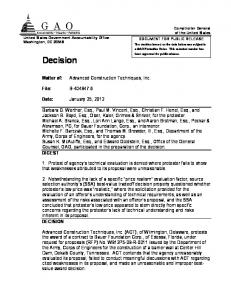
Fig.9. Diagram of frequency parameters at the terminals of a three-phase consumer balanced in dynamic system
ISBN: 978-960-474-257-8
51
Advances in Computational Intelligence, Man-Machine Systems and Cybernetics
involve getting involved goal. Because of this, optimization tests generally cover a very small part of the problem. To determine the field by designing circuits regulating it define the precise movements of the machine to try to define the specification and rules with a sufficient degree of precise details of the settlement so that the circuit is well known. Until now, to the electric machines all methods began with the final configuration and geometric evaluation after repeated analysis is made to find the optimum solution. The way to do this search for solutions to machine parameters is automatically highlighting the degree to which order to define the optimal solution is very variable. Users of software dedicated to the left first attempt to make the determination of optimized parameters of different configurations of electric machines and, on the other hand, processing of the results obtained. Also, by the method of multiple search procedure can be done to define objectives, and later to realize automatic filling of the problem by choosing solutions without user intervention. Final configuration, starting from the initial state of the machine makes it impossible to determine the broader parameters, typical for early definition of the choice of type of motor (usually the winding coils, cold rolled electromagnetic materials etc.). The procedures for choosing the type of motor and drive certainly not enter into detailed projections of the motor without prior specifications. In this study are highlighted in the computer methods used for automated search optimization and determination of parameters. The basis for these methods is to define a single objective function can be determined with minimal effort. During this time attention was directed to search for new methods for determining the operating parameters involving an element happened in their searches and which seems to prove the most suitable method evolved schemes.
In Fig. 9 are shown diagrams of frequency parameters for the case of a small power induction motor commanded by a frequency converter. We recalculate the expression of equation 46, by tansforming of coordinate reference system, one can see that the value function has to be not greater than the vector size is fundamental to a fixed coordinate system (synchronous rotation): ω1t = xc , ω1 = ω c . From this expression we observe that is a fundamental component higher than the vector represented in synchronous rotation system.
6 Conclusions Nowadays due to the use of devices and microelectronic semiconductor electronic devices, electromagnetic techniques were replaced with efficiency and high precision control. Electromagnetic converters have become often the simplest; allowing obtaining any desired mechanical characteristics of any type of motors. This comes from the need to identify stationary and dynamic parameters of electric machines controlled by static converters simultaneously with the identification of dynamic phenomena and deforming schemes introduced by them. However this does not mean that all types of engines are equal in terms of price, performance control, efficiency, optimal weight etc. This means that the electromagnetic structure and operating principle can be another crucial influence on the effectiveness and improving the energy system. That's why these, today more attention from the previous period, through better use of new materials and design of magnetic and electrical circuits [8]. The structure of such machines is often performed especially given electronic control and mechatronics to create specific converters. Electronic control system performance has improved only energy but also changed the general philosophy of design and complete development of new types of machinery. For further progress in this area is necessary to consider simultaneously supplying the electronic circuit and electromagnetic field structure [9], [10], [11]. A conventional electronic control (with pulse modulation PWM), has some typical disadvantages include: high bandwidth of the fundamental harmonic voltage, pulses of torque, the influence of asymmetry in the structure, especially at low angular speed, the need for additional external cooling in low speeds, radio interference and energy with relatively low efficiency of machines. Synthesis presented in the paper, to assess parameters of induction machines, is the reverse analysis and design techniques is conducted so as documented in the context of experimental measurements and / or math. The design is obviously much more than represents a synthesis. Designers will identify the concept of optimization with different computer codes and procedures, and that
ISBN: 978-960-474-257-8
References: [1] VLĂDESCU, C., STAN, M.F., IONEL, M., Supple electrical drives optimization for metallurgical industry, Bibliotheca Publishing House, Târgovişte, 2009, ISBN 978-973-712-300-8. [2] STAN, M.F., VÎRJOGHE, E.O., IONEL, M., Electrical Engineering Treaty, vol. I, Bibliotheca Publishing House, Târgovişte, 2005, ISBN 973-712099-X; [3] IONEL, M., STAN, M.F., Electrical machines and electrical drive system. Electronic converters commands, Bibliotheca Publishing House, Târgovişte, 2005, ISBN 973-8413-648;
52
Advances in Computational Intelligence, Man-Machine Systems and Cybernetics
[4] IONEL, M., STAN, M.F., Electrical Engineering Treaty, vol. II, Bibliotheca Publishing House, Târgovişte, 2006, ISBN 978-973-712-191-2. [5] IONEL, M., STAN, M.F., DOGARU, V., IONEL, M.O. Posibilities of Diminishing the Distortions Introduced by Superior Harmonics of Electric Current, Proceedings of 6th WSEAS International Conference on Simulation, Modelling and Optimization, Lisbon, Portugal, September 22-24, 2006, pp. 689-692, ISSN 1790-5117; [6] STAN, M.F., IONEL, M., IONEL, O.M., Modern automatic system for the optimization of the electrical drives for working machines with mechanical branches, Proceedings of 8th WSEAS International Conference on Mathematical Methods and Computational Techniques in Electrical Engineering, Bucharest, Romania, October 16-17, 2006, pp. 5-8, ISSN 1790-5117; [7] IONEL, M., STAN, M.F., VÎRJOGHE., E.O., Techniques of induction machine vectorial order simulation, Proceedings oft he 9th WSEAS/IASME International Conference on Electric Power Systems, High Voltages, Electric Machines, Genova, Italy, October 17-19, 2009, pp.202-207, ISSN: 1790-5117, ISBN: 978-960-474-130-4; [8] IONEL, M., STAN, M.F., SĂLIŞTEANU I.C., IONEL, M.O. Advanced command techniques of electrical induction machines, Proceedings of the 9th WSEAS International Conference on Power Systems (PS '09), Budapest, Hungary, September 3-5, 2009, pp.176-180, ISSN 1790-5117; [9] STAN, M.F., IONEL, M., Double-fed induction machines, Proceedings of International Symposium on Electrical Engineering, ISEE 2005, 17-19 oct. 2005, Târgovişte, DâmboviŃa, pp. 89-92, ISBN 973712-101-5. [10] M. IONEL, M., STAN, M.F., SĂLISTEANU I.C., IONEL, O.M., Control Systems for High Power Induction Machines, WSEAS TRANSACTIONS on POWER SYSTEMS, Issue 7, Volume 4, July 2009, pp.232-241, ISSN: 1790-5060; [11] IONEL, M., STAN, M.F., IVANOVICI, T., The integration of the a.c. machines command system, Scientific Bulletin of the Electrical Engineering Faculty, no. 1 / 2009, Bibliotheca Publishing House, Târgovişte, June 2009, pp. 23-27, ISSN 1843-6188.
ISBN: 978-960-474-257-8
53