2 Lebrun, Ph. et. al., Cooling Strings of Superconduction Devices below 2 K: the Helium II Bayonet. Heat Exchanger, paper presented at CEC/ICMC Portland ...
EUROPEAN ORGANIZATION FOR NUCLEAR RESEARCH European Laboratory for Particle Physics
LHC Project Report 221 Large Hadron Collider Project
Applying Advanced Control Techniques for Temperature Regulation of the LHC Superconducting Magnets Bjørn Flemsæter1, Enrique Blanco1, Juan Casas-Cabillos1, Cesar de Prada2, Steinar Sælid3
Abstract The temperature of the superconducting magnets for the future LHC accelerator is a control parameter with strict operating constraints imposed by (a) the maximum temperature at which the magnets can operate, (b) the cooling capacity of the cryogenic system, (c) the variability of applied heat loads and (d) the accuracy of the instrumentation. A temperature regulation with narrow control band can in principle be achieved by implementing a Model Predictive Control (MPC)-type controller. For this purpose, and for investigating the behaviour of the cooling system, a simulation program has been developed. A prototype MPC controller has been installed and completed its first run.
1
LHC Division, CERN, Geneva (Switzerland) ISA Universidad de Valladolid, Valladolid (Spain) 3 ITK Norwegian University of Science and Technology (Norway) 2
Presented at ICEC 17, 14-17 July 1998, Bournemouth, UK
Administrative Secretariat LHC Division CERN CH - 1211 Geneva 23 Switzerland Geneva, 10 August 1998
Applying Advanced Control Techniques for Temperature Regulation of the LHC Superconducting Magnets Bjørn Flemsæter1, Enrique Blanco1, Juan Casas-Cabillos1, Cesar de Prada2, Steinar Sælid3 1
LHC Division, CERN, Geneva (Switzerland) ISA Universidad de Valladolid, Valladolid (Spain) 3 ITK Norwegian University of Science and Technology (Norway) 2
The temperature of the superconducting magnets for the future LHC accelerator is a control parameter with strict operating constraints imposed by (a) the maximum temperature at which the magnets can operate, (b) the cooling capacity of the cryogenic system, (c) the variability of applied heat loads and (d) the accuracy of the instrumentation. A temperature regulation with narrow control band can in principle be achieved by implementing a Model Predictive Control (MPC)-type controller. For this purpose, and for investigating the behaviour of the cooling system, a simulation program has been developed. A prototype MPC controller has been installed and completed its first run.
1 INTRODUCTION The Large Hadron Collider (LHC) [1] project will be the next major research facility for high-energy physics. It will provide proton-proton collisions based in a 26.7-km ring of high-field superconducting magnets operating in superfluid helium at about 1.9 K. It represents a major challenge in applied superconductivity and cryogenics, and imposes hard constraints and a strict range of temperature for operation of the machine.
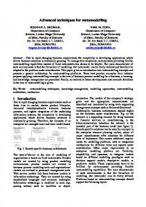
2 SYSTEM DESCRIPTION AND PROCESS CHARACTERISTICS 2.1 The 1.9 K cooling loop The superconducting magnets operate in static baths of pressurized HeII at 1.9 K and 1 bar. The generated or deposited heat is transported by conduction to a heat exchanger tube (Hx) threading its way along the magnet string, thus constituting a linear cold source. Inside the tube, a flow of saturated HeII absorbs the heat load by gradual vaporisation [2]. The superfluid helium cooling scheme for the future LHC will be implemented in independent cooling loops (cells), each constituted of eight separated but thermally linked magnets totalling 107 meters. The configuration of the present test facility roughly represents a half-cell, consisting of four slightly shorter magnets with a total length of 35 meters, but with the basic cryogenic cooling concept being identical (see figure 1). It is mounted on a 1.4 % slope, reproducing the maximum slope inside the LHC tunnel [3].
2
Helium gas to pump
Joule Thomson valve
4
1.9 K heat exchanger Quadropole
Dipole 1
Dipole 2
Dipole 3
4.2 K 1.15 bar
3
2
1
3.1 K 2.2 K
1.8 K
Overflow pot
Q
Q
Q
Q
Pressurized He II at 1.9 K & 1.1 bar
Subcooling heat exchanger
Lambda plate
Coldmass
Figure1 The 1.9 K cooling loop
Subcooled helium I (1) is expanded to saturation by throttling through a Joule Thomson (JT) valve (2) and fed to the far end of the corrugated heat exchanger tube (3). The liquid gathers heat and vaporises as it flows back in co-current flow with the vapor, and is then pumped out (4). 2.2 Process characteristics The mass of pressurized HeII in the cold mass is about 160 kg compared to the several tons of metal, but it still constitutes 99 % of the specific heat (Cp) at 1.9 K. Most physical parameters are highly nonlinear in the temperature range of interest, for example Cp of HeII more than doubles its value from 1.8 K to 2.1 K. The Hx tube is only partly wetted over its length during normal operation. When more cooling power is required, the JT-valve opens and the additional liquid will have to flow over the already wetted length to participate in the cooling. At the same time both the amount of flash gas from the JT valve and the pressure drop along the Hx tube increase, leading to a higher local saturation temperature. This effect leads to an inverse response where the cooling decreases in a transient period (typically 5-10 min).
3 MODELLING & SIMULATION Models of real systems are based on hypotheses and approximations and are therefore never perfect. They are however helpful in process analysis and control by improving the understanding of the process, to design the control effects and the control law, and finally to optimize the process operating conditions. There are in principle two main approaches for obtaining mathematical models of a system. (a) First-principle models ("white box") constructed from fundamental physical laws such as conservation of mass, energy and momentum. They are able to explain process behaviour under different operating conditions, but are in general difficult to embed in a linear model-based controller. (b) Identified models ("black box"), describing the relationship between input and output measurements of a plant. They are obtained from experiments on the plant, and can only describe the operational band and the dynamics that are present during the observation period. 3.1 Assumptions and simplifications The velocity with which the liquid flows in the Hx-tube has been observed to be fairly constant and in the model is taken as constant. The latent heat of vaporisation of helium, the percentage of flash over the JT valve and the heat transfer coefficient (kglobal) from saturated to pressurized HeII along the wetted perimeter inside the Hx tube are assumed constant. Cooling is thus a function of wetted length and ∆T from saturated to pressurized helium. kglobal includes the solid conduction through the Hx wall and Kapitza conductances on the two solid-liquid interfaces. The magnets are assumed to be isothermal thanks to the good heat transfer along the half-cell.
3
3.2 Challenges and solutions The dynamic behaviour of the saturated liquid helium flow along the Hx tube has proved to be one of the most complex parameters to model. A good understanding of liquid quantity and location and the pressure profile along the Hx tube is important, as this determines the cooling provided to the system. To achieve this, the Hx tube is discretized longitudinally and in each element mass and energy balance as well as pressure drop are calculated. A trade off between accuracy and complexity has to be made. When the cooling provided by the Hx tube is known, the calculation of the magnet temperature is straightforward. The differential equations for pressure drop, magnet temperature and mass balance are respectively:
ρ (T ) ⋅ v gas dp = f dt 2⋅d
2
∫
Lincr
0
dx
dT q heatloads − ∑ q cooling = dt m HeII ⋅ Cp (T )
dm = m� in − m� out − q cooling / h fg dt
The cooling power, mass and gas flow out of each element are found from these relationships respectively: q cooling = ∆T ⋅ Lincrement ⋅ k global
m� out = (m − m threshold ) ⋅ v liq Lincrement
g out = g in + q cooling / h fg
During each time step, these calculations are performed for each length increment, except dT/dt as the geometry is assumed isothermal. (f -friction factor, d -tube diameter, vgas -gas velocity, qheatloads -heat load, m -mass of helium in increment, hfg -latent heat of vaporisation, Lincrement -length of discretization increment, mthreshold accounts for corrugations in the Hx tube)
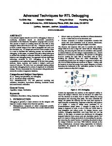
Figure 2 First-principle model simulation (bold lines) versus measurement (thin lines)
Figure 2 shows the comparison between simulation with a first-principle model and experimental data, and a good agreement is obtained. To calculate magnet temperatures and pressure profile along the Hx tube the model requires knowledge of the JT-valve position, pressure in the overflow pot and applied heat load.
4 PROCESS REGULATION The process is characterised by being non self-regulating (integrating process), having a variable dead time (transport lag in the Hx tube), exhibiting inverse response (as the temperature initially rises when the valve is opened and vice versa) and being non-linear (particularly in Cp). These are all complicating factors from a control point of view. The prototype half-cell has been regulated by a PID (Proportional, Integral, Derivative) regulator. PID regulators are not optimal when non-linearities, long dead time and inverse response are present in the process, and it is interesting to assess the advantages of using another control technique. The MPC approach refers to a class of algorithms that compute a sequence of manipulated variable (MV) adjustments (∆u) in order to optimise the future behaviour of a plant (y) over a time interval known as the 4
prediction horizon. The algorithm has imbedded a model of the plant, and the optimisation is achieved by minimising a cost function of the form: J = ∑ j = N 1 [y (t + j ) − w(t + j )]2 + β ∑ j =1 [∆u(t + j )]2 N2
NU
where N1 and N2 bound the prediction horizons, between which the MPC will try to follow an internally calculated reference trajectory w(t) [4]. NU is the control horizon where different MV adjustments are calculated, and β is the weight factor for the adjustments. The prediction horizon is a basic tuning parameter, and should be set long enough to capture the steady-state effect of all computed MV adjustments. Advantages of the MPC methodology are that it incorporates treatment of constraints, has dead-time compensation and permits to solve control problems with unusual dynamics. On the other hand it is computationally complex and requires a suitable process model able to predict future outputs. In principle a narrower control band can be obtained with MPC when comparing with PID algorithms.
5 FIRST RESULT AND FURTHER WORK A first-principle model of the LHC Test String facility has been developed and tested. It is capable of simulating the plant behaviour over a prolonged period, and is useful for developing and testing control aspects. A MPC control algorithm has been implemented on the Test String. This algorithm is working with an identified plant model, but it is the goal to develop and implement a suitable first-principle model. Figure 3 shows a real response obtained from a step in the reference. Note that the regulator is anticipating the rise in temperature, and starts closing the valve even before the Figure 1 Measured step response with MPC control actual temperature rise starts. Such a response cannot be obtained with a PID-algorithm. Potential benefits of implementing an advanced controller versus PID are expected to offset the increased initial cost and technical complexity. Considering the plant characteristics and control challenges this represents, also taking into account the future 107-m layout, we believe that the improvement will be noticeable, and it will add to a robust and fault-tolerant operation of the system. 6 ACKNOWLEDGEMENT This work initiated by Ph. Lebrun, has been performed in the framework of the Doctoral Student Programme at CERN (B.F), and the European Training and Mobility of Researchers (TMR) Programme (E.B.). We would like to thank the String Team for help and co-operation. 7 REFERENCES 1 2 3 4
Evans, L.R., The LHC in: Proceedings ICEC16/ICMC Kitakyushu, Elsevier Science, Oxford (1997) 45-52 Lebrun, Ph. et. al., Cooling Strings of Superconduction Devices below 2 K: the Helium II Bayonet Heat Exchanger, paper presented at CEC/ICMC Portland USA (1997) Casas-Cubillos, J. et. al., Operation, Testing and Long Term Behaviour of the LHC Test String Cryogenic System, paper presented on this conference Clarke, D.W., et. al., Generalized Predictive Control, Automatica Vol23 (1987) 137-160 5