Advanced Modulation Techniques for Polymer Optical Fiber Transmission Sebastian Randel (1), Ton Koonen (2), Jeffrey Lee (2), Florian Breyer (3), Maria Garcia Larrode (2) Jia Yang (2), Anthony Ng'oma (2), Gert-Jan Rijckenberg (2), Henrie van den Boom (2) 1 : Siemens AG, Corporate Technology, Information and Communications, Otto-Hahn-Ring 6, 81730 Munich, Germany,
[email protected], 2 : COBRA Institute, Eindhoven University of Technology, Eindhoven, The Netherlands, 3 : Institute for Communications Engineering, Munich University of Technology, Munich, Germany Abstract POF is a very attractive medium for broadband in-house networks. An overview is given on recent progress in advanced modulation techniques for Gigabit-Ethernet transmission over POF as well as high-capacity radio-over-POF at high microwave frequencies. Introduction Today, it is a common vision that the networks of the future will enable a wide variety of digital services such as mobile TV, video conferencing, gaming, and 3D-entertainment [1]. All these services impose high demands to either the data-rate, quality of service, or on the degree of mobility. Wireless technologies such as WLAN and WiMAX are often favoured, as they do not require any cabling. However, due to physical constraints these technologies will not be capable for gigabit communication. Latest developments in wireless such as UWB, “60 GHz” and optical wireless focus on high data-rates in small spatially confined cells, often referred to as femto-cells. In order to feed this kind of premises networks a wired “backbone” network will be required in order to ensure high datarates and quality of service. In this scenario the polymer optical fibre (POF) is a highly attractive alternative to the common twisted pair cable, as it allows a reliable high speed data transmission as well as do-it-yourself installation even by the untrained end-user [2]. This paper gives an overview about advanced modulation formats suitable for such POF-based high-speed “backbone” networks. While the first section analyses in particular modulation formats for Gigabit Ethernet transmission over Step-Index POF, the second section gives an overview about radio-over-POF transmission at high microwave frequencies.
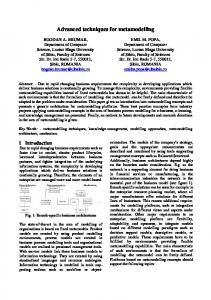
by the end-customer. In this respect the Step-Index POF (SI-POF) with a 1mm core diameter has become a highly attractive transmission medium as it can be simply cut to length with a razor blade and plugged into the transceiver even without any connector. Recently, several media-converter products were launched offering Fast Ethernet transmission over up to 30 m SI-POF [3]. In order to ensure futureproofness their capability for Gigabit Ethernet transmission has to be demonstrated [4]. The SI-POF typically has a numerical aperture of 0.5 allowing for bending radii well below 25 mm. However, this high aperture also leads to a reduced bandwidth of approximately 50 MHz per 100m. Electronic equalization as well advanced modulation techniques like multiple sub-carrier transmission combined with multilevel modulation are promising approaches to enable gigabit communication. Electronic equalization is a well understood method to reduce inter-symbol interference (ISI) [5] and has recently been adopted in the 10GBase-LRM standard [6] in order to combat modal dispersion in glass fibre systems with up to 220 m length. A similar approach seems promising also for the POF. Fig. 1 shows a performance comparison of different equalizer realizations for Gigabit Ethernet transmission. 0
10
raw analog 3 taps
-2
analog 4 taps
BER
Gigabit Ethernet transmission over SI-POF The IEEE 802.3 Ethernet standard has become the most dominant networking technology in office and home networks today. Personal Computers (PCs) commonly include several electrical Gigabit Ethernet ports and so do home gateways and switches. It seems likely, that future home networks will be based on the Gigabit Ethernet standard with some extension to guarantee a certain quality of service upon request. In order to realize cost effective premises networks it is important to keep the installation cost as low as possible. From an operators point of view, a premises network is preferred that can easily be self-installed
10
APP no ISI DFE 5,3 FFE 7
-4
10
10
11
12
13
14
15 SNR in dB
16
17
18
19
20
Figure 1 : BER versus electrical signal-to-noise ratio after 1.25 Gbit/s transmission over 50 m SI-POF. The simulations are based on a measured electrical system response to an input signal modulated with a pseudo-random-binary sequence (PRBS) of order 7.
5 0
Normalized electrial power (dB)
-5
transmitted
-10
received
-15 -20 -25 -30 -35 -40 -45
0
50
100
150 Frequency (MHz)
200
250
300
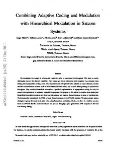
Figure 2 : transmitted and received DMT spectrum for LED-based transmission of 753 Mbit/s over SI-POF. This raises the question whether the DMT approach will allow Gigabit Ethernet transmission with LEDbased transmitters. Compared to red lasers that provide sufficient bandwidth, LEDs have several advantages such as longer lifetime, lower cost, no need for a monitoring photodiode, and eye-safety. In Fig. 2 the transmitted and received electrical spectra for back-to-back DMT transmission over SI-POF with a 650 nm LED in the transmitter are plotted. The DMT signal fills a bandwidth of 150 MHz and consists of 511 carriers, each of them modulated with a 32-ary QAM signal resulting in a net bit-rate of 753 Mbit/s (including FEC overhead). The carriers above approximately 120 MHz encounter a high attenuation due to limitation of both the LED bandwidth as well as the bandwidth of the receiver’s trans-impedance amplifier (TIA). (b)
imaginary part
(a)
imaginary part
The setup consists of a ball-lensed DVD-laser diode coupled to a 50 m long SI-POF. In the receiver a GaAs PIN diode with an active diameter of 250µm is used. In order to be able to separate ISI and noise the received waveform was averaged and the receiver noise is added numerically for varying signal-to-noise ratios (SNR). Without equalization (raw) the eye diagram is fully closed, while in the reference case (no ISI) an electrical signal-to-noise ratio (SNR) of -5 12.6 dB is required for a bit error ratio of 10 . Even a relatively simple feed-forward equalizer (FFE) with 7 taps is able to reduce modal dispersion induced ISI considerably and allow for error free reception with an electrical power penalty of 6.5 dB, corresponding to a 3.25 dB penalty in terms of optical power. The nonlinear decision feedback equalizer (DFE) with 5 forward and 3 feedback taps gives only a slight performance improvement in the order of 1 dB. The SNR requirement can be further reduced to 15 dB by using a relatively complex a-posteriori probability (APP) equalizer structure. This structure can be well approximated by an analogue APPequalizer structure with 3 or 4-taps. Not only from its performance but also from its implementation complexity this equalizer structure is very attractive as it does not require analogue-to-digital conversion and thus allows a chip design with small footprint and lowpower consumption. Multiple sub-carrier transmission is an alternative approach for Gigabit Ethernet transmission over SIPOF. Recently 1 Gbit/s transmission over 100 m SIPOF has been demonstrated. Thereby a spectral efficiency of 6.3 bit/s/Hz was achieved by modulation of 80 sub-carriers with up to 256-ary quadrature amplitude modulation (QAM) [4]. A very similar technique called discrete multi-tone (DMT) modulation is used today e.g. in digital subscriber line (DSL). DMT can be regarded as a real-valued subclass of orthogonal frequency division multiplex (OFDM). The idea behind this technique is that the individual carriers are modulated in the frequency domain. The transmitted signal is then generated using the inverse fast Fourier transform (IFFT). In the receiver the carriers are efficiently separated by a single fast Fourier transform (FFT). One advantage of the multiple sub-carrier modulation technique is the possibility to adapt the transmit spectrum as well as the modulation format to the channel characteristic even far beyond the 3-dB bandwidth. A further benefit of the technique is the high spectral efficiency of 32-ary or even higher-order QAM allowing a compression of the required bandwidth for 1 Gbit/s transmission to 200MHz or even below. Thereby, the technique does not only allow for increased transmission distances but also requires less bandwidth at the receiver and at the transmitter [7].
real part
real part
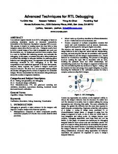
Figure 3 : Received constellation diagrams for the 32ary QAM modulated carriers at (a) 30.8 MHz and (b) 155.6 MHz, respectively. Fig. 3a and Fig. 3b show received constellation diagrams for carriers at 2.9 dB and 19.5 dB attenuation relative to DC (compare Fig. 2), respectively. Besides the receiver noise, critical issues of the DMT modulation are the effective resolution of the analogue-to-digital converter and timing jitter. The impact of the LED’s nonlinear characteristic can be mitigated by the use of methods for reduction of the peak-to-average-power ratio
(PAPR) like rotation of the carrier phases and selective mapping [8]. Future work will concentrate on improved receiver structures as well as efficient coupling from the LED into the SI-POF. Furthermore, resonant-cavity LEDs (RC-LEDs) with 3-dB bandwidths larger than 100 MHz will be investigated.
pre-compensation in the driving amplifiers of the LEDs will be pursued to improve the overall linearity.
Wavelength-Sliced Emulated QAM Quadrature Amplitude Modulation techniques are widely used, e.g. in wireless LANs, DVB-C and DOCSIS cable modems. For POF high capacity transmission links, one may benefit from the low-cost QAM chip sets readily available. As discussed in [10] and [11], M-ary QAM may be emulated on a POF link in various ways using such a chip set. The baseband processor (BBP) chip converts the incoming serial binary data into the in-phase (I) and quadraturephase (Q) multilevel signals, which usually are modulated on the two orthogonal phases of a carrier wave by the quadrature modulator chip. In an alternative approach, the M-QAM signal can be transmitted without a carrier wave by putting the I and Q signals in two different wavelength channels, as shown in Fig. 4.
Figure 5: Experimental setup
I
data in
POF
SLED S
BBP S
WDM slicer
PD WDM S demux S
Q
BBP
VSG QAM mod.
coupler
I signal VSG QAM demod.
λ demux LPF
1 mm SI-POF link
Q signal blue LED
Q signal
Radio over POF In a converged in-house POF-based network, the goal is to carry broadband wired data services as well as broadband wireless services in a single POFbased network, as illustrated in Fig. 6 [12]. Radioover-fibre is a cost-effective approach to accommodate the wireless services. It allows to consolidate all the microwave signal processing at a central site in the house, e.g. in the residential gateway, thereby simplifying the antenna sites and thus reducing the costs of installation, maintenance and upgrading.
Satellite dish
data out
MD FD
Twisted pair network Coax cable network
Q
Figure 4: Wavelength-sliced emulated QAM The channels may be created from a low-cost LED by spectral slicing. At the receiver site, the wavelength channels are demultiplexed and by another BBP chip the serial data output stream is reconstituted. By avoiding the carrier wave, the system can operate in baseband and thus puts significantly lower bandwidth demands on the POF link. This approach can also improve the receiver sensitivity, resulting in a better symbol error rate at a given received optical power (see [10, 11]). To assess the basic feasibility of this concept, a first test setup has been built as shown in Fig. 5. The system has been tested with 50 and 100 metres of 1 mm core step-index PMMA POF. The I signal was sent by a red LED, having a central wavelength of 658 nm and an output power of 1.1 mW, and the Q signal by a blue LED with a central wavelength of 460 nm and 1.2 mW output power. The QAM signals were generated by a programmable Vector Signal Generator (VSG). With a 15 MBaud 16-QAM signal (so 60 Mbit/s data rate), the error vector magnitude (EVM) measured at the VSG QAM demodulator was 14.4% for the 100 m link, and 15.5% for the 50 m link. Clearly these quite high EVM values are not dominated by noise, but by the non-linear characteristics of the LEDs and PDs. As a next step,
TIA LPF
I xtalk elim.
PD
red LED I signal
POF
MD
MD
RG
Fibre network
MD FD
FD
Figure 6: In-building network using POF (FD: fixed device; MD: mobile device; RG: residential gateway) However, the modal dispersion in the POF links prohibits bringing the microwave signals by direct intensity modulation over the POF network. The Optical Frequency Multiplication technique [12, 13] has been shown to be quite robust against modal dispersion (as well as chromatic dispersion in singlemode fibre). The operation principle of the OFM technique is shown in Fig. 7. fmm = 2N · fsw λ sweep signal
fsw MZI
τ LD
- data fibre -τ
PD
ampl. BPF
τ + data
Figure 7: Optical Frequency Multiplying The optical frequency of a wavelength-tuneable laser diode is periodically varied with a relatively low sweep frequency. A subsequent Mach Zehnder Interferometer (MZI) with a periodic bandpass characteristic performs an FM-to-IM conversion of this signal. Thus a multitude of harmonics of the sweep frequency is generated. At the antenna site, a photodiode is followed by a bandpass filter which selects the desired harmonic frequency, and after
amplification this microwave signal is radiated by the antenna. Theoretical analysis and laboratory experiments show that the microwave signal is very pure, independent of the laser linewidth due to the phase-noise cancellation in the signal conversion process. Hence comprehensive modulation schemes can be applied, allowing high data rates. The OFM technique has also been shown to be robust against modal dispersion in multimode fibre [13, 14]. A 64QAM system with 120 Mbit/s on a microwave carrier of 17.2 GHz has been demonstrated over 4.4 km 50 µm core silica graded-index multimode fibre [15]. Recently also a bi-directional 100 Mbit/s 16-QAM radio-over-POF system has been demonstrated over a 100 metres link of 50 µm core graded-index POF [16]. The upstream path was created by downconversion at the antenna site of the received upstream microwave signal, using a local oscillator signal which is remotely delivered by the OFM downlink. When looping back the downstream 16-QAM 17.2 GHz microwave signal at the antenna site, a clean constellation diagram with an EVM of only 4.8% was obtained (which is well below the IEEE 802.16 WiMAX specifications). The 50 µm POF core size was chosen as the high-speed photodiode was equipped with a 50 µm MMF pigtail; successful link operation a larger POF core size is expected to be feasible when a larger-core MMF pigtailed photodiode is available. Conclusions Several approaches for high speed data transmission over POF have been discussed. The first section focuses on Gigabit Ethernet transmission over SIPOF. The performance of several equalizer structures has been compared. The results show that even relatively simple FFE equalizers provide considerable increased link lengths. Analogue equalizer implementations will allow small footprint and low power consumption chip design. On the other hand the high modulation bandwidth requires the use of high bandwidth transceivers incorporating red lasers. It has been shown that the DMT modulation format has the potential to allow gigabit communication even with LEDs. However, high-speed digital signal processing is required in the transmitter and the receiver. Alternatively, wavelength-sliced emulation of QAM signal transmission can achieve spectrum-efficient high-capacity data transfer while operating the POF link in baseband. The transport of high capacity wireless signals (such
as 100 Mbit/s at 16-QAM) has been demonstrated over more than 100 meters of POF. The results reveal the potential of POF for fixed-wired Gigabit Ethernet transmission as well as for transmission of wireless high-capacity signals, and thus ensure the future-proofness of POF infrastructure installed in premises networks today. This work was partially funded by EU project FP6-IST STREP “POF-ALL”, and the EU projects FP6-IP “MUSE” and FP6-NoE e-Photon/ONe. References [1] R. Tafazolli (Ed.), “Technologies for the Wireless Future”, vol. 2, Wiley, 2005. [2] O. Ziemann, “Polymer Optical Fibers for Data Communication”, Springer, 2002. [3] Gigaset Optical LAN Adapter Duo, http://gigaset.siemens.com/shc/0,1935,hq_en_0 _129657_rArNrNrNrN,00.html [4] S. Randel et al., ECOC 2006, paper PDP Th4.4.1. [5] J. G. Proakis, “Digital Communications”, McGraw-Hill, 2000. [6] IEEE P802.3aq 10GBASE-LRM Task Force [7] S.C.J. Lee et al., Tech. Dig. OFC 2007, paper PDP 6. [8] Y. Li and G.L. Stüber (Eds.), „Orthogonal Frequency Division Multiplexing for Wireless Communications“, Springer, 2006. [9] J. Lambkin, “Advanced Emitters for Plastic Optical Fibre”, ICPOF 2002. [10] R. Gaudino et al., Proc. ECOC 2007, Berlin, Sep. 16-20, 2007 [11] A.M.J. Koonen, J. Yang, M.S. Alfiad, X. Li, H.P.A. van den Boom, Proc. OFC 2007, paper OMR6, Anaheim, Mar. 25-29, 2007 [12] A.M.J. Koonen et al., Proc. ECOC 2007, Berlin, Sep. 16-20, 2007 [13] A.M.J. Koonen, A. Ng’oma, in in Broadband Optical Access Networks and Fiber-to-theHome: System Technologies and Development Strategies. New York: Wiley, 2006 [14] M. Garcia Larrode, A.M.J. Koonen, J.J. Vegas Olmos, IEEE PTL, Vol. 18, No. 22, 2006, pp. 2428-2430 [15] A. Ng’oma, A.M.J. Koonen, I. Tafur-Monroy, H.P.A. van den Boom, G.-D. Khoe, Proc. of OFC 2005, Anaheim, Mar. 6-11, 2005, paper OWB2 [16] A. Ng’oma, J. Zeng, H.P.A. van den Boom, Y. Watanabe, A.M.J. Koonen, Proc. Asia-Pacific Microwave Photonics Conf., 2007