AbstmcI-Thk paper outlines the theoretical backgmund and the results of advanced RF calibration pmcedures specially suited to support wafer level RF device ...
Advanced On-Wafer Multiport Calibration Methods for Mono- and Mixed-Mode Device Characterization Holger Heuermann*, Andrej Rumiantsev**, and Steffen Schott**
* Univ. of Applied Sciences Aachen, Institute of High Frequency Tech., Germany, 52066 Aachen, Eupener Str. 70
** SUSS MicroTec Test Systems GmbH, Germany, 01561 Sacka, Sussstr. 1
AbstmcI-Thk paper outlines the theoretical backgmund and the results of advanced RF calibration pmcedures specially suited to support wafer level RF device characterization with monoandlor mixed-mode interfaces. The analysis of on-wafer measumment systems bring up the benefits of using load standards, reflectometers, as well as the GSOLT-model to perform high quality device characterizations. Based on the large uomher of possible methods to combine two-port calibration algorithms with multiport techniques, two methods were derived and investigated focusing on on-wafer devices. The mults of our experiments demonstrate the effectiveness of novel RRMT onwafer Calibration method for multiport devices.
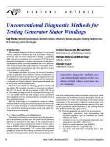
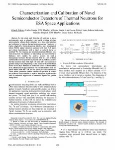
correction techniques. However, RF engineers, performing onwafer measurements, are familiar with calibration methods and the necessary standards. The reasons being the complexity of on-wafer standards and the on-wafer devices under test (DUTs) which are critical components for accurate modeling of the devices. Therefore, calibration methods are established for one- and two-port on-wafer measurements. The most often used methods are SOLT3, [19], and the selfcalibration procedures TRL4, [l], LRM', [3], and LRRM (LinelReflectlReflectatch),[41, [12]. SOLT relies on fully known standards, which is difficult to I. INTRODUCTION achieve at wafer level beyond 40GHz, [131,[14]. In contrast to The accurate modeling of microwave devices is necessary to the SOLT, the advantage of the self-calibration procedures (e.g. develop communication products on low cost semiconductors TRL, LRM, etc.) is that the reflection standard uncertainty and MMICs. A correct modeling of semiconductors needs (radiation, losses, and an imperfect phase behavior) can be precise on-wafer measurement data. To ensure the validity of ignored without any affect to the calibration accuracy. the measured data, the RF test equipment must be calibrated. The inability to compensate for imperfect transmission lines In the past decades, many RF calibration methods for two- limits the on-wafer TRL frequency range [13]. Other TRL port scattering parameter measurements have been published drawbacks include multiple transmission lines, repositioning and many of them are established [ 11-[6]. Meanwhile, for both the probes and the requirement of the very long transmission network analyzer architectures, the reflectometer-concept and lines for low frequencies [20]. the reference-channel concept, multiport calibration methods Conventional LRM calibration sets the reference impedance are published [7], [PI. to the value of the ideal match standard. NIST LRM uses an The purpose of the presented work was to design a multiport arbitrary match, hut the match must be similar for both ports calibration procedure, which is optimized for on-wafer con- 161. LRRM [41, [12] like the QSOLT procedure, 1171, relies ditions. The algorithm must support mono- and mixed-mode on the measurements of the load standard at one port only. interfaces, [9]. This approach is free of the possible port's asymmetry of the This paper describes the requirements of an on-wafer mea- planar load standard, but it sets the reference impedance of surement system for multiport devices, including calibration the second measurement port inaccurately 1181. standards, vector network analyzer (VNA) architectures as To perform a self-calibration without any systematic error, well as error-correction algorithms. A new and very short a VNA based on the reflectometer architecture is needed. theory for calibration and error-correction of multiport VNAs This kind of VNA has, in the three-port case, six measurebased on the reflectometer-concept is presented. The results ment channels as shown in Fig.1. The basics of a multiport of sections IV and V introduce the multiport-LRRM'- and calibration for this kind of VNA are based on the 7-term model the novel RRMT'-procedures. Results representative of the and are published in 171. RRMT-method show that this procedure is a very robust and However, for the VNA architecture with less measurement accurate calibration method. channels, (Fig. 2) a different multipat method was published, [PI, which is based on the 10-term model6. This GSOLT7 11. ON-WAFERMEASUREMENT SYSTEM Users of VNAs for measurements of devices with coaxial standards are not familiar with on-wafer calibration and error-
'SOLT is the abbreviation for Shon/Opefiine,Thm is the abbreviation for TlmlReAectKine 'LRM is the abbreviation for Line/ReflecdMatch 'The IO-tem'model is the basic model of the 12-term SOLT-model. 'The name GSOLT is the Shon form of General SOL7
'LRRh4 is the abbreviation for LimlReflectlReRect/Match. 'RRhlT is the abbreviation for R e E e c U R e f l e a , M a t ~ .
91
m^
r
a.
-, , ",
measurement channels
shown in Fig. 1. The block diagram shown in Fig. 1 can be separated into two double-reflectometer VNAs: Using the first and second state of the switch, the error matrices [A] and [BI]-' can be calculated with a standard two-pon calibration TXX-procedure, [SI, as well as any method which fits the 7term model, e.g. TRL. With the first and third state of the switch, the 7 parameters of the error boxes A and BII can also be calculated by using a TXX-procedure. The notation is using the transmission parameters
networks
[Mx] = [A] [Nx][Bi]-'
FLg I Block diagnm of a 3-port vector netwrk analyzer with three pom and SIX measurement chvlnels (mple-reflectometer)
method can also be used for VNAs, based on the referencechannel or reflectometer concept. m"
-
a,
with the measurement mabix [Mx] for the DUT [Nx], [SI. The number of error coefficients is 3 for the error box A and 4 * ( ~ 1 for ) ~ the transmission calibration steps, i.e. 401 error coefficients in total,
A. GTXX Ermr Correction Pmcess It is useful to invert the error matrices for the GTXX m u l t i p t error correction process.
[GI = [A]-' , [Hi] = [Bj]-'
, (i = I , I I )
(2)
Refemng to Fig. 1, the relations
measurement channels Fig. 2.
networks
Block diagram of a 3-port vector network analyzer with four
measurement channels (reference-channel architecture)
In comparison between the two calibration procedures, the 7-term model and the IO-term model shows avowedly that the 7-term Drocedure has so-called bracinm. - .1111. . The main dilemma of these hracings are, that the error-corrected measurements do not include the full transmission dynamic performance. Procedures using the IO-term model are much more robust. Because of this deficiency, for multiport on-wafer calibrations we combined the GSOLT-technique and the LRMprocedure, which results in the RRMT-method. We compared RRMT with another multiport 7-term model calibration pro, cedure, which also required two unknown reflection standards hut only one match. Next a simplified theory for the multipoa 7-term model is presented.
hold in every state of the switch for the inverted transmission
parameters. That means that for a three-port, all three sets of error corrected incident and reflected wave values
(5) can be calculated with high accuracy, Finally, we can combine the three sets of S-parameter
equations
the
equation
111. THEORY OF GTXX
The way to calibrate or to error-correct the multiport VNA with the GTXX8-procedure is described by using a threeport triple reflectometer VNA. These results can easily be extrapolated to n-port VNAs. The block diagram with the error networks of a three-port triple-reflectometer VNA is
[Sx] = [K][L]-'
.
to calculate the error-corrected S-parameters. 9n: Number of
%TXX stands far General T m .
92
the measurement pom.
(7)
~
B. A Comparison of GSOLT and GTXX
. ..
The advantages of GTXX: Less calibration measurements. Many possible self-calibration standards. Easy to create calibration standards can he used. Switch can have poor isolation.
The advantages of GSOLT Less measurement channels = cheaper VNAs. More robust for high dynamic measurements. To overcome the drawback of GSOLT for on-wafer measurements which require perfect open and short standards, we have derived GSOLT in the most general way of three reflection standards with known hut not ideal reflection parameters. Using this common approach we are able to use the results of TXX self-calibration algorithms, which were already done for RRMT.
derivation is the same as the presented GSOLT, [2], [SI, hut the equations are much more complex, [IO]. In this way, RRMT uses the benefits of the LRM-technique and the robustness of the GSOLT-procedure (10-term model) respectively. Errors in the match standards have no influence on the measurement's performance apan from the fact that the real values of the match standards establish separate system impedances for the forward and the reverse direction scattering parameters. The last can he easily overcome defining the arbitrary match standard for each port independently according to [131, [15], 1161, and [211.
II ss
i io'
MM
T
Fig. 4. Calibration standards of the RRMT-procedure
IV. THEORY OF MULTIPORT-LRRM-PROCEDURE
The theory of the two-port LRRM method is well-known, [4], [12], by using the standards shown in Fig. 3.
L Fig. 3. Calibration standards of the LRRM-prwedure
Since the match standard is only contacted at one port, the GSOLT-model can not he used for the multiport procedure. Thus we described in [lo] how to realize the multiport-LRRMprocedure based on GTXX. V. THEORY OF THE NOVEL RRMT-PROCEDURE It is well known that the self-calibration process works with high accuracy for the reflection standards. In addition, only a thru and a load are attractive candidates for on-wafer measurements. The assumption that the loads are identical and the used 7-term model are the reasons for the so-called hracings of the conventional LRM procedure. The traditional solution to overcome this problem the measurement of the load standard at one port only (e.g. LRRM procedure). However, as described in [IO] and [21], this approach has many other drawbacks. Our new solution to overcome the bracing problem of conventional LRM is the RRMT-procedure. The RRMT procedure consists of the following steps: We use the self-calibration process to calculate the accurate values of the open and the short standard (The bracing of the LRM-procedure have only negligible effect on the calculation of the highly reflective self-calibration values), We use, for the calculation of the Rstandards, the most robust formula for 7-term procedures, [SI. We already have four well-known standards: Rl=S, R k 0 , M=L, T, all with non-ideal hut known values. So, we derive the GSOLT-procedure with non-ideal values. The mathematical
93
VI. MEASUREMENT RESULTS We used the multiport network analyzer from Ballmann" over the frequency range of 1 GHz to 6 GHz (maximum) to measure the raw data in ASCII-SxP-format. The raw measurement data has been read out and processed on an extemal computer. A four-port RRMT-procedure was implemented in Matlah. Fig. 5 shows the top-view of a used differential thrustandard and the dual IZI-probes, manufactured by SUSS MicroTec.
Ftg. 5. On-wafer calibration standard for differential thru
Fig. 6 outlines a similar substrate to the one we used. Fig. 7 shows the full set-up we used including the SUSS PA200HF Probe Station. The first example for self-monitoring values of the RRMT is given in Fig. 8 with an illustration of the self-calibration results of the short-standard. However, this and some other figures show a measurement error at 3GHz. This error was caused by the test-set of the used network analyzer. lome Ball"
network analyzer family S20X is based on a X-
reflectometer.We used an S-port network analyza
-$
-
0.4 :
:
.:........................
o,*
~
. . . . . . . . . . (. .......................
c
-Lo 0 - o 3 :
................ c4,2 m
s i
~
...............................
>.........
4.4 '
Fig. 6. On-wafer calibration and verification substrate
Fig. 8. RRMT-resultsin magnitude and phase of the self-calibration p m for shon-standard -
g
3
.-
P a
0.4
.
o.2
~
i:. . . . . . . . . .:...
:
.!.. . . . . . . . . . . . . . . . . . . . . . . . . . . . . . . . . . . . . . . . . . . . . . . . . . . . . . . . .
::
4.4 ' 1
2
3 Frequency
Fig. I .
4
5
6
5
6
(GHz)
Set-up for the on-wafer meaFurements
Fig. 9 shows the self-monitoringvalues of the open-standard calculated from the self-calibration process of the RRMTprocedure. Both self-calibration results indicate that the set-up and selfcalibration process works excellently.
-10 I. 1
2
3 Frequency
4
I
(GHz)
Fig. 9. R M - r e s u l t s in magnitude and phase of h e self-calibration part for open-standard
The following results are error-comected four-port RRMTusing the four-port RRMT-method: measurements. However, a long matched transmission line with an open VII. CONCLUSION end is a very hard test (so-called ripple test) for a network In this paper, advanced RF-techniques to perform accurate analyzer set-up. Positive results of the magnitude at port 4 RF-on-wafer multiport measurements were presented. A large (Fig. 10) illustrate once more the robustness of the RRMT- number of multiport calibration procedures can. be designed. procedure. Tko of them were derived and compared regarding the onAlso, the reflection value of a long matched line is a good wafer conditions. A comparison was done with experimental proportion for verfication. Fig. 11 shows that the results are measurements. The results clearly demonstrated proof of the better than -3OdB. advantages of the new multiport RRMT calibration procedure. The last measurement results in Fig. 12 illustrate the very ACKNOWLEDGMENT accurate measurement performance of the RRMT-multiport The authors are grateful to MI. Ballmann, who provided the procedure for transmission measurements. The results of a long line connected between port 1 and 4 were calculated by multiport network analyzer S208. 94
0.2.:. . . . . . . . . . . . . . . . . . . . . . . . . . . . . .
. . .: . . . . . . . . . .:
- 1
j...
0 i . . . . . . . . . .: . . . . . . . . . j . . . . . . . . . .
. . . . .
I
..:... . . . . . . . .
~
............
c
-04L 1
hP g -20o
!.
-;
2
3 Frequency
4 (Ob)
5
I
6
.................................
4 ........................................................
-e 0
. . . . . . . . . . . . . . .: . . .
.............
4 0 .......... ..j . . . . . . . . . . . : . . . . . . . ..: . . . . . . . . . . . . . . .
4
-I"
1
2
3 Frequency
4
5
(GHz)
Fig. IO. Magnitude of RRh4T emor corrected measwemen1 results of a long matched oansmission line with an open end, CoMected at port 4
-10. . . . . . . . . . . .: . . . . . . . . . . . . . . . . . . . . . :... . . . . . . . :. . . . . . . . . . .
s-20 .~ . . . . . :. . . . . . . . . . . . . . . . ;. .......................
e
-1mL
6
:
Fig. 11. Magnitude of RRMT emr corrected reflection measurement mule of a long transmission line, connected between poti 3
REFERENCES [I] ENGEN.G.F., HOER,C.A., Tbm-Reflect-Line: An Improved Technique for Calibrating the Dual Six PoR Automatic Network Analyze& IEEE T m s . Microwave Theory Tech., MlT-27. Dec. 1979, pp. 987-993 (21 HEWLETTPACKARD,Automating the HP 84108 Microwave Network Analyzer, Application Note 221A. Jun. 1980. [31 EUL, H.J.. SCHIEK,B.. k-Match-Reflect: One Result of a Rigorous Theory for &-embedding and Network Analyzer Calibration, Proceedings Ofthe European Microwave Conference. Stackholm 1988, pp. 909-914 A., JONES,K., STRID, E., LRM and LRRM Calibrations [4] DAVIDSON. with Automatic Determination of the Load Inductance, ARFTG Digest Dec. 1990, pp. 57-64 [5] HEUERMANN,H.. SCHJEK,B.. Robust Algorithms for T u Network Analyzer Procedures, IEEE Trans. Inst". Mas.. Feb. 1994. pp. 1823
2
3
Frequency
4
(GHz)
5
1 6
Fig. 12. Magnitude and phase ofRRMT error corrected measurement results of a long transmissionline. connected between port 1 and pan 4
[6] WILLIAMS,D., MARKS, R., LRM Probe-Bp Calibration using Nonideal Standards, IEEE Trans. Micrwave Theory Tech., vol. 43, No. 2, 1995, pp. 466-469 [7] FERRERO,A.. PIsANI, U., KERWIN,K.J., A New Implementation Of a Multiport Automatic Network Analyzer, IEEE Trans. Microwave Theory Tech., vol. 40,Nov. 1992. pp. 2078-2085 [SI HEUERMANN, H., GSOLT: The Calibration Procedure for all Multi-Pon Vector Network Analyzers. MTT-S International Microwave Symposium, Philadelphia, 2003, pp. 1815-1818 [9] STENGEL,B., Mined-Mode S-Parameters Measurements and Applications, m - S Intemational Microwave Symposium, Workshop WMO, Seattle, 2002 [lo] HEUERMANN,H.. Kalibrierverfahren zur Durchfuehrun% von Mehnormessungen auf Halbleiterscheiben. Invention P I03 14 463.3 from 25.03.03 [ I l l HEUERMANN,H..SCHIEK,B.. 15-Term Self-Calibration Methods for the Error-Comction of On-Wafer Measuremenu, IEEE Trans. ."snI Meas., IM-5,Oct. 1997, pp. 1105-1110 [I21 PURROY,F.. PRAVELL,L., New ?heoretical Analysis of the LRRM Calibration Technique for Vector Network Analyzers, IEEE Trans. Insmm. Meas, IM-5. Oct. 2001, pp. 1307-1314 1131 WILLIAMS,F., Characferization of ?hin-Film Calibration Elements, 38th AWTG Conf. Digest, 1991, pp. 25-36 [I41 IMPERATO,M.. WELLER,T., DUNLEAVY,L., On-Wafer Calibration Using Space-Consenative (SoLT Standards, MlT-S International Microwave Symposium June 1999. pp. 1643-1646 [I51 WALKER,D.. KAISER, R., WILLIAMS,D., COAKLEYK., LumpedElement Models for On-Wafer Calibration, 56th ARFTG Cod. Digest, 2oW. pp. 89-92 1161 . . KIRBY. P.. DUNLEAVY,L.. WELLERT.. Load Models for CPW and Microship SOLT Standards on GaAs, 56th ARFKi Conf Digest, 2oW 1171 FERRERO,A., PlSANI, U.,QSOLT: A New Calibration Algorithm for Two Port S - P m t e r Measurements, 38th ARFTG Conf. Dig., San Diego, Dec. 1991. pp. 5-6 [I81 JARGON, J., MARKS,R., RYTTING. D., Robust SOLT and Alternative Calibrations for FotwSampler Vector Network Analyzers. IEEE Trans. Microwave Theory Tech., vol. 47. No. IO, 1999, pp. 2008-2013 [I91 KRUPPA.W., SOVOMSKY, K., An Explicit Salurion for the Scattering Parameters of a Linear W*Port Measured with an Imperfect Test Set, IEEE Trans. Microwave Theory Tech., Jan. 1971, pp. 122-123 [20] MARKS,R., A Multiline Method of Network Analyzer Calibration, LEF.E Trans. Microwave Theory Tech., Vol. 39, No. 7, 1991, pp. 12051215 011 SUSS MICROTEC,Application Overview High Frequency Probing, December 2002 ~~
95
96