engineering distributed systems tend to adopt a model-based approach to .... The Tropos methodology [7,28] is an agent-oriented software development method ...
Agent-Oriented visual modeling and model validation for engineering distributed systems. Anna Perini and Angelo Susi ITC-irst, Via Sommarive, 18, I-38050 Trento-Povo, Italy {perini,susi}@itc.it
Abstract. Agent-Oriented methodologies that have been recently proposed for engineering distributed systems tend to adopt a model-based approach to software development, that is they devise a development process based on the definition of a specific set of models for each steps in the analysis and the software design phases. To be put into practice, this approach demands clear guidelines for building and refining models along the software development process, as well as flexible modeling tools which integrates automatic verification techniques at support of model validation. In this paper we describe a modeling environment which integrates an AgentOriented (AO) modeling tool with other tools, such as a model-checker for the verification of formal properties of the model and a library which implements graph transformation techniques which can be used to support model refinement as well as model transformations. In designing it we took into account recommendations from the OMG’s Model-Driven Architecture initiative. We illustrate the modeling environment architecture, give details on the AO modeling tool and on the components that allows for the integration with other tools. Examples of how modeling and validation can be interleaved and supported by the modeling environment are given.
1 Introduction Conceptual modeling in software system engineering is considered a best practice which favors the communication among the stakeholders involved in the development process and supports project documentation. In Object Oriented approaches this practice has become popular thanks to the diffusion of CASE tools such as UML modelers which provide an effective support for the definition of a conceptual model via building diagrammatic representations (views) of the model itself. Nevertheless, UML modeling is still affected by limits such as subjectivity and difficulty in exploiting automatic verification techniques for model validation. Conceptual modeling assumes an even more critical role in model-based development approaches to software engineering. In model-based development, a model serves as the primary representation of a system under development. It should be able to capture different properties of the system and of its environment, such as domain features and customer expectations and it has to be refined and transformed to a model of the architecture and detail design of the system-to-be, and finally to code. The model-based
approach demands tools that support model specification providing adequate expressive power, for instance allowing the integration of specification languages which are suitable to represent dynamic properties with languages which are appropriate to model structural properties, as well as tools that provide transformation mechanisms to execute the translation steps in a transparent and simple manner. Current Agent-Oriented (AO) methodologies for engineering distributed systems tend to adopt a model-based development approach. They all define a set of models (or views on a model) corresponding to specific steps in the analysis and design of software. For instance, GAIA [31] considers a four stages process which starts upon the collection of requirements, with an analysis step, followed by architectural design, detailed design and implementation. For both the analysis and design steps, specific models are to be defined. Differently from the process proposed in GAIA, the Tropos methodology prescribes a preliminary stage, called early requirements, followed by late requirements, architectural design, detailed design and implementation steps [7]. GAIA does not commit to a specific modeling language while Tropos builds its own notation upon the i* framework [30]. Other AO methodologies propose their own modeling language defining appropriate UML stereotypes, for instance PASSI (Process for Agent Societies Specification and Implementation) [4] and MESSAGE [9]. More recently, the AUML [1] effort which aims at extending UML with additional abstraction and notation has been strengthened inside the FIPA initiative. The lack of effective CASE tools is still limiting the experimentation of these methodologies in industrial settings and, more generally, makes difficult their diffusion. In this paper, we describe an environment for supporting a model driven software development approach adopting an Agent Oriented methodology. Its architecture allows for a flexible integration of different tools. The current version includes a modeler that supports the analyst when building an informal specification using the Tropos methodology and a component that allows for its automatic transformation into a formal specification which can be verified by a model-checker. The modeling environment supports the adoption of a framework, that has been previously proposed [29], which rests on a light integration of informal and formal languages. Moreover, the platform includes the interface to a graph rewriting library, i. e. the Attributed Graph Grammar (AGG) system [13] that will be used to support model refinement [27]. In designing it we are taking into account basic directives, such as meta-modeling standards, coming from the Model-Driven Architecture (MDA) initiative of the OMG. The paper is structured as follows. Section 2 discusses basic motivations of this work and provides examples of how visual modeling and model verification are exploited in our approach. Relationships with the Model-Driven Architecture (MDA) initiative of the OMG, which is proposing a model-based approach to software engineering [8] and it is going to guide the development in this area by providing technological infrastructures and standards [20], are also pointed out. Section 3, presents a practical approach to interleaving visual modeling a model validation via model-checking techniques and the main requirements of a tool that aims at supporting this approach; section 4, describes the modeling environment architecture and how to use it. Related works are discussed in Section 5. Finally, conclusion and future work are presented in Section 6.
2 Background 2.1 The Tropos methodology The Tropos methodology [7, 28] is an agent-oriented software development methodology which provides a visual modeling language that can be used to define both an informal specification and a formal one. From a practical point of view, the methodology guides the software engineer in building an informal, conceptual model that is incrementally refined and extended from an early requirements model, namely a representation of the organizational setting where the system-to-be will be introduced, to system design artifacts, according to a requirements-driven approach. The Tropos language allows to model intentional and social concepts, such as those of actor and goal, and set of relationships, such as actor dependency, goal decomposition, means-end and contribution relationships. These elements support the modeling of basic goal analysis techniques. An actor models an entity that has strategic goals and intentionality, such as a physical agent, a role with respect to a given context, or a set of roles (i.e., a position). Goals represent the strategic interests of actors. Two basic type of goals are considered, namely hard and soft goals, the latter having no clear-cut definition and/or criteria as to whether they are satisfied. Softgoals are useful for modeling goal/plan qualities and non functional requirements. A dependency between two actors indicates that an actor depends on another in order to achieve a goal, execute a plan, or exploit a resource. Basic modeling activities in Tropos include the identification of the actors with their goals and of the actors mutual dependencies. Each goal can be analyzed from the point of view of the individual actor considering: possible sub-goals (AND decomposition); means to satisfy these goals (means-end relationship); alternative ways to achieve a specific goal (OR decomposition); goals or plans or resources that can contribute positively or negatively to its achievement (contribution). All these models can be depicted using two basic types of diagrams, namely, actor and goal diagrams (an example is given in Figure 1). A detailed account of modeling activities can be found in [7]. An informal specification in Tropos provides a “static” view of the organizational setting and of the dependencies among the different elements of the domain. A Formal Tropos (FT hereafter on) specification [14, 16] extends a specification with annotations that characterize the valid behaviors of the model. In FT the emphasis goes in modeling the “strategic” aspects of the evolutions of the model. Thus, an FT specification consists of a sequence of entity declarations such as, actors, goals, and dependencies which contain temporal constraints expressed in Linear Temporal Logic (LTL hereafter on). These constraints describe the valid lifetime evolutions of the model in terms of temporal evolutions of set of instances of the model’s entities. For instance, two critical moments in the life-cycle of goals and dependencies are the instants of their creation and fulfillment. The creation of a goal is interpreted as the moment in which the owner or depender expects or desires to achieve the goal, while its fulfillment is the time in which the goal condition is actually achieved. In FT, creation and fulfillment constraints can be used to define conditions for these two moments in the life of intentional elements. Creation and fulfillment conditions cab be used, for defining constraints on the lifetimes of subgoals in a goal decomposition (sub-goals are created after the parent goal and should be
fulfilled before the parent goal can be fulfilled), or for defining the responsiveness of an actor with respect to the dependencies (an actor can take care immediately of some of them while delaying other dependencies). FT also provides invariant constraints that define conditions that should be true throughout the lifetime of model instances. Typically, invariants define relations on the possible values of attributes, or cardinality constraints on the instances of a given entity. 2.2 Interleaving visual modeling and model validation
LEGEND Advisor Actor
manage pheromone trap plant
goal
(A)
goal A
hystorical data analysis goal 3
goal 1
monitoring device data
goal 2
orchards hystorical data lab data
OR-Goal_Decomposition orchards data Producer
Goal_Dependency
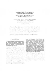
Fig. 1. A Tropos goal diagram built by the analyst.
... Goal Dependency OrchardsData Depender Advisor Dependee Producer Mode achieve Creation condition ∃ ohd : OrchardHistoricalData ((ohd.actor = depender) ∧¬ Fulfilled(ohd)) Invariant ∃ ohd : OrchardHistoricalData (ohd.actor = depender)
Fig. 2. FT specification of the goal dependency orchards data, shown in the Tropos diagram in Figure 1, between the Advisor and the Producer.
In [29] we proposed a framework which rests on the interleaving of informal modeling with automatic model validation.
Advisor
....
Advisor
Advisor
manage pheromone trap plant
manage pheromone trap plant
(A) hystorical data analysis
Advisor manage pheromone trap plant
manage pheromone trap plant
....
.... 1
orchards hystorical data
orchards hystorical data
orchards hystorical data
0
hystorical data analysis
hystorical data analysis hystorical data analysis
orchards data
Producer
4
orchards data Producer
5
Fig. 3. Frame sequence depicting a trace produced by the model-checker while verifying the satisfiability of goal labeled (A) in Figure 1.
In practice, we consider the possibility to formally annotate the entities, which are diagrammatically depicted in a visual model, and to check the resulting specification via model-checking techniques, in order to discover new constraints in the domain that are able to guide the refinement of the model and to produce scenarios that can be analyzed by a stakeholder for their validation. This process can lead to a combinatorial explosion when dealing with formal representations of a whole model. To control this complexity component we proposed two strategies: from one side the use of LTL logics and of symbolic model checking; from the other the set up of a check procedure that can be carried on only for subsets of the model (e.g. goal dependencies hierarchies). In Figure 1, is described a Tropos diagram that can be enriched with FT properties via annotations. In particular, it represents a goal decomposition of the (A)-labeled goal; this goal can be fulfilled if at least one of the goals of the decomposition is fulfilled (ORGoal decomposition). This static model can be annotated as depicted in Figure 2 that shows how the LTL clauses are integrated in an entity declaration for describing, for instance, the valid creation and invariant conditions for a dependency. This representation can be checked in order to verify its properties, such as the satisfiability of the goal (A), by querying the underlying formal representation using model-checking techniques. In this case, the result of the query can be visualized as a sequence of frames, showed in Figure 3 that describes the fulfillment of the goal (A). Each frame corresponds to a step of the trace produced by the model-checker, where goal instances are created and fullfilled (in gray color) respectively. Another type of property that can be checked is considered in the following example; it focuses on the possibility that more than one activity can be carried on together. It basically correspond to the following question: is the model able to capture possible mistakes in the ordering of goal fulfillment? Considering the example depicted in Figure 1, the property to be checked can be informally stated as follow: In the case more than one lab data activities can be performed before a monitoring device data, is it always the case that all instances of lab data relative
to the same orchard have to be fulfilled before fulfilling the monitoring device data for the orchard? This query can be formulated as follows: are all the instances of lab data fulfilled before all the instances of monitoring device data? which can be rewritten as the following LTL formula: Global Assertion F ( ∀ a : Advisor (∀ hda : HistoricalDataAnalysis (hda.actor = a → ∀ mdd : MonitoringDeviceData (mdd.hda = hda → Justfulfilled(hda) → ∀ ld : LabData (ld.hda = hda → Fulfilled(ld))))))
In this case, T-T OOL generates a counter-example scenario, illustrated by the bar-charts diagrams depicted in Figure 4 where the bars represent the life-cycle of four instances of goals specified in the visual model: historical data analysis, lab data [A], lab data [B] and monitoring device data. Every single instance of goal can go from a “not created” status, the dashed area of the bar, to a “created” status, the light gray area of the bar to a “fulfilled” status, the dark gray area of the bar. The scenario shows that it is possible to fulfill the second instance of lab data (LD[B] in the diagram) after the monitoring device data (MDD) has already been fulfilled. Indeed, annotations have to be added
Historical Data Analysis Lab Data [A] Lab Data [B] Monitoring Device Data
LD[A]
MDD
LD[B]
Fig. 4. Another validation scenario for the goal lab data with two instances.
to the FT model in order to implement the constraints on the temporal orders that are agreed with the stakeholder, refining the existing visual model. On the other hand, the understanding of these constraints is very important for a deep understanding of the whole application domain, and their elicitation is very difficult in a purely informal framework. The validation, analysis and refinement, is a recurrent process that is undertaken during the different phases of software development (i.e. early requirement, late requirement, architectural design in Tropos). 2.3 Current trends in developing CASE tools In developing tools for supporting the described process we are taking into account emerging guidelines and standards from the OMG’ Model-Driven Architecture (MDA) initiative which proposes an approach to software development based on modeling and
automated mapping of models to code. A basic motivation of MDA is that of improving quality, by allowing for the reuse of models and mappings between models, and software maintainability by favoring a better consistency between models and code. One of the basic concepts in MDA is that of distinguishing between a software design which is platform independent (Platform-Independent Models, PIM) from a software design that includes all the platform specific details (Platform-Specific Models, PSM). The two models can be related through a transformation process which converts a PIM to its semantically equivalent PSM. A PIM model can be the result of a chain of transformations between different abstraction level PIMs, which may include, as in our case, interleaving of formal and informal specification languages. Even if the MDA initiative refers mainly to Object Oriented software development and to system design activities, we think that the emerging ideas are of interest to Agent Oriented software engineering as well [17]. In MDA, the use of various modeling concepts and notations is foreseen with the idea to favor the exploitation of existing specification languages that are more appropriate to define views on dynamic aspects rather than of structural aspects of a given model. From a practical point of view, the MDA initiative is proposing a standard to which the meta-models of the specification languages used in the modeling process must be compliant with, that is the Meta Object Facility (MOF), and a set of requirements for the transformation techniques that will be applied when transforming a source model into a target model, this is referred as the Query/View/Transformation (QVT) approach. The MOF version which is currently available is the 1.4 which both the Tropos and the FT modeling languages meta-models are compliant to. For what concerns QVT, on one side OMG is working on the specification of the MOF 2.0 QVT requirements, and on the other side several techniques for model transformation have already been proposed. According to the classification proposed in [11] our approach to model transformation corresponds to a “Direct-Manipulation” approach to model transformation. More specifically, we are exploiting Visitor patterns implementing the structure of the models and the operations to be executed on them, in order to transform the informal Tropos model to the corresponding model in the target specification language (i. e. FT for now). In parallel, we are considering Graph Transformation techniques that have been already pointed out as a promising technology to provide mechanisms for the automatic synchronization of different views in a model or for translating a model given in a specification language to a different one. Along this line we are integrating the visual modeler with the AGG system [13], which implements graph rewriting techniques.
3 Supporting visual modeling and model validation in practice. According to the framework briefly recalled in Section 2.2 during the software development process the analyst performs activities such as: building a specification through visual modeling (1); annotating the Tropos visual model with properties that can be represented in FT (2); querying the model (3) in order to perform the assessment of the model against possible inadequacies, incompleteness and inconsistencies or to validate
the resulting specification with the domain experts or the stakeholders; managing the model refinement and evolution steps (4). The process is sketched in Figure 5. Activity (3) rests on validation through model-checking (see activities 5, 6).
Visual Model
(1)
annotation
(2)
Query Model
(3)
Result analysis and Model refinement
Translation into FT specification
(5)
Model Checking
(6)
(4)
Fig. 5. Visual modeling and model validation. A sketch of the process that we intend to support. Some of the activities could be completely automated, gray color, other require a mixed-initiative (analyst, tool) approach.
Advisor manage pheromone trap plant
historical data analysis
(A) orchards historical data
lab data
FT specification
Actor Advisor ... Goal OrchardsHistoricalData Actor Advisor ... FullFillment Condition ... Exists LD: LabData( (LD.actor=actor and Fullfilled(LD))
Added constraint: The goal "lab data" has to be fulfilled before the goal "orchards historical data"
Fig. 6. Adding a temporal constraint to a specification.
Main requirements of a modeling environment which supports this process are discussed in the following. – Visual Modeling The modeling environment should support the user during the specification of an AO model in a graphical manner, e.g. according to the Tropos visual notation as shown in Figure 1. We adapted the Tropos language meta-model given in [7]. The
–
–
–
–
system should be able to represent the basic entities defined in this meta-model like actor, goal, plan, resource and the relationships between them like the dependency, the and-or decomposition, the means-end and the contribution. The modeler should allow to represent new entities that could be included in the Tropos meta-model or in language variants, as well as to restrict the set of representable entities to a subset of the visual language, in an easy way. The meta-model of the visual modeling languages supported should be compliant to the Meta Object Facilities (MOF) directives that allow to specify, build and manage technology neutral meta-models. Annotation via LTL logic formula The modeling environment should support easy annotation of the visual model with invariants, creation or fulfillment conditions. In Figure 6 is described an example in which the goals involved in an OR decomposition are constrained, via an LTL formula (contained in the box) to be fulfilled in a given order (in particular the goal lab data has to be fulfilled before the goal orchards historical data). This constraint can not be represented in the visual model. Automatic Model Translation The modeling environment should allow to save a model in a standard format (e.g. XML or XMI), and automatically translate it into other target specifications languages in order to exploit services like automatic verification. In this case every entity in the Tropos specification is translated in the language required by the FT model-checker (as shown the example in Figure 2). The modeling environment should be extensible and allow the integration of other tools. A modular design will allow to add new components. Automatic Verification and Validation The resulting formal specification should be queried by the analyst in order to perform the assessment of the model against possible inadequacies, incompleteness and inconsistencies or to validate the resulting specification with the domain experts or the stakeholders. The query should be translated into an assertion that the model-checker will verify producing positive scenarios and/or counterexamples. Results Representation and analysis The output of the automatic verification activity (e.g. of the model-checker) should be represented in an effective way, in order to provide the user the information he needs for model refinement. This represents an open issue. Possible ways of presenting an evolving scenario is the one depicted in Figure 3 where a sequence of creation and fulfillment for the goal is given, or in Figure 4, where a counterexample to a given assertion is given in the form of a bar-chart.
4 The modeling environment The modeling environment that we are developing for enabling a model-based software development approach rests on a modular architecture which is sketched in Figure 7. Its main component called TAOM (Tool for Agent-Oriented Modeling), is a tool which supports the user while building a Tropos visual model. The tool allows to annotate each model entity with properties that can be formally represented. This core component can be integrated with other components, such as the T-T OOL [15], which is an
Fig. 7. The modeling environment structure: the Agent-Oriented (AO) modeling tool (TAOM) is connected to other tools, such as a model-checker for the verification of formal properties of the model (T-T OOL ) through the I2F module. The Graph Transformation interface component integrates a graph transformation techniques library.
automatic verification tool for the FT modeling language based on the N U SMV model checker [10]. The I2F component provides an integration between the visual modeler and the model checker. It takes in input the description of the visual model specified by TAOM and queries from the analyst. The T-T OOL produces in output a scenario stating the truth of the query or a counterexample in the case the query is false. The Graph Transformation Interface integrates the modeler with a library implementing graph rewriting techniques. Currently we are exploiting the AGG library and we have represented correct model transformations in Tropos as a set of AGG rules [27]. This will allow to get a continuous verification of the model refinement process. Moreover, a complete trace of the process can be derived. A basic choice was to work within an open source environment. In the rest of this section we give more details on the modeler and on the I2F module, then we briefly illustrate how to use the modeling environment. 4.1 The TAOM Component The Agent-Oriented modeler component is based on a framework named Graph Editing Framework (GEF)1 , a library of Java classes for the visual representation and management of connected graphs which has been exploited for other modeler such as ARGOUML2 . The library implements the Model-View-Controller (MVC) pattern and assumes that a model can be represented as a graph composed by set of nodes, a set of ports that can be associated to a node, and a set of edges, an edge connects two ports of a given type. 1 2
http://gef.tigris.org/ http://argouml.tigris.org/
BASE Editor Selection Mode Cmd
CONTROLLER
BASE_TAOM CmdActorCreation
PRESENTATION Fig
VIEWER
ArrowHead
PRESENT_TAOM
FigActor FigGoal FigDependency
GRAPH
MODEL
NetNode NetPort NetEdge
GRAPH_TAOM
Actor Goal Dependency
Fig. 8. The UML package diagram of TAOM.
The UML package diagram depicted in Figure 8 corresponds to the GEF implementation of the MVC pattern, namely: – The package Base represents the controller component for the system. It is a collection of the basic classes for the application, such as the class for the editing function: the classes Selection and Mode, that combines the selection and management functionalities of the graphical objects and the classes of the type Cmd, that contains the functions for the editing management and for the control of the interaction with the user. – The package Presentation implements the GEF viewer component. It contains the classes that define the basic graphical components of the framework. They can be grouped in two main categories, namely, the polygons and the lines that allow to build new pictures. – The package Graph represents the model. It contains the definition of the basic component of the graph model, in particular it defines the classes NetNode, NetEdge and NetPort respectively devoted to the representation of the graph nodes, edges and ports that allow the connection via an edge to the other nodes in the graph model. The use of the MVC pattern results in a more flexible architecture. The GEF packages have been extended to support Tropos visual modeling as shown in Figure 8. In particular, the package Presentation has been extended with the creation of the package Present TAOM to represent the visual part of the entities of the Tropos framework; it contains classes like FigActor, FigGoal that uses the class FigNode as a basis for the Tropos entity visual representation. The package Graph has been extended with the package Graph TAOM to represent the entities of the Tropos meta-model and of their properties; it contains the classes Actor, Goal, and Dependency, that extend and use the classes NetNode, NetPort and Net-
Fig. 9. The UML class diagram for the Tropos Metamodel.
Edges. To allow for the definition of a model following the Object Management Group (OMG), the Tropos metamodel has been defined via a UML class diagram (shown in Figure 9) adopting the MOF (Meta Object Facilities) directives that allow to specify, build and manage technology neutral meta-models. For the model implementation we adopted the Java Metadata Interface, JMI, that enables the implementation of a dynamic, platform-independent infrastructure to manage the creation, storage, access, discovery, and exchange of metadata. Finally, the persistence of the model has been assured via the representation of the model in XMI, the OMG standard for serializing model and meta-data in XML, that allow also the sharing of the model between the environment components. The package Base has been extended in Base TAOM to take care of the new functionalities. If we need to extend the visual language with a new element we simply follow these steps: the new element and the description of its relationships with the other elements is defined in the (MOF compliant) UML meta-model; the entity is then defined as a class of the package Graph TAOM as an extension of classes of the package Graph; finally, elements for its graphical notation are defined in the Present TAOM package and control functions related to the manipulation of the new entity can be defined in the package Base.
ITNode -nodeName: String -nodeIndex: int +ITNode() +accept() +setName() +getName() +setIndex() +getIndex()
ITGoal
ITActor
+ITGoal() +accept()
+ITActor() +accept()
ITMeansEnd +ITMeansEnd() +accept()
ITPlan +ITPlan() +accept()
ITDependency +Depender: ITActor +Dependee: ITActor +ITDependency() +accept()
ITResource +ITResource() +accept()
ITDecomposition +ITDecomposition() +accept()
ITContribution +metric: int +ITContribution() +accept()
Fig. 10. The set of Informal Tropos Nodes.
4.2 The I2F transformation module The I2F module is one of the bridging modules that have been implemented in the modeling environment. It allows to integrate TAOM with the T-T OOL. The architecture of the module is based on a “Direct-Manipulation” approach to the model transformation; in particular we used a visitor to implement the transformation from the informal Tropos model to the FT one. A model developed with TAOM is saved as an XMI file containing the specification of the properties of the entities of the model and including the entity annotations which can be represented in LTL. The model’s XMI file is given in input to the transformation module which produces the correspondent FT specification and gives it in input to the T-T OOL. Figure 10 and Figure 11 show the UML design of the transformation module which exploits the visitor pattern [19], a well known design pattern that allows to add new operations without changing the classes of the elements on which they operates; this characteristic is particularly useful in the design of a generic parsing environment, like the one we describe here, since in general the elements of a language are more stable respect to the operations executed on them. The visitor, showed in the class hierarchy in Figure 10, allows to represent the element of the Tropos informal model, like ITActor, ITGoal, ITDecomposition, as a realization of the abstract class ITNode. The visiting methods such as visitITActor, visitITGoal, visitITDecomposition, specified in the visitor class TransformIT2FT, shown in Figure 11(b), allow to transform the Tropos entities to the FT entities specified by the realization of the abstract class FTNode in Figure 11(a). Notice that the visit methods operates the translation according to the mapping between informal Tropos and FT concepts. Figure 2 gives an example of this mapping for the goal dependency concept. It contains several condition for the creation and fulfillment of the goal specified via first order Linear Temporal Logic (LTL) formulas. If we need to transform a Tropos model (the source model) into a different target specification language, once having defined a mapping between the concepts of the source and the target specification language, we can design a new class hierarchy describing the target model entities (such as those introduced for FT) and a new visitor
FTNode
Visitor
-nodeName: String -nodeIndex: int +FTNode() +accept() +setName() +getName() +setIndex() +getIndex()
FTActor +FTActor() +accept()
FTDependency +Depender: String +Dependee: String +FTDependency() +accept()
(a)
+Visitor() +visitITActor() +visitITElement() +visitITDependency() +visitITDecomposition() +visitITContribution() +visitITMeansEnd() +visitFTActor() +visitFTDependency() +visitFTEntity()
FTEntity +FTEntity() +accept()
TransformIT2FT +TransformIT2FT() +visitITActor() +visitITElement() +visitITDependency() +visitITDecomposition() +visitITContribution() +visitITMeansEnd() +visitFTActor() +visitFTDependency() +visitFTEntity()
WriteFT +WriteFT() +visitITActor() +visitITElement() +visitITDependency() +visitITDecomposition() +visitITContribution() +visitITMeansEnd() +visitFTActor() +visitFTDependency() +visitFTEntity()
(b)
Fig. 11. The set of FT Nodes that maps the Tropos entities (a) and the set of visitor classes that implement the I2F transformation (b).
class hierarchy where the transformation operations between corresponding entities are defined. 4.3 How to use it Figure 12 depicts the graphic user interface of TAOM. The screen is divided in four main areas: the Tropos diagram palette on the top, the diagram editor, the message window at the bottom and the properties editor at the right. TAOM allows the analyst to define a new Tropos diagram by selecting from the palette the desired Tropos entity and drawing it in the diagram editor. For every model refinement operation, the AGG graph rewriting system verifies its correctness against the specified rewriting rules, and send information about the validity of the operation which will be displayed in the message window. For every Tropos entity it is possible to specify properties that can be represented formally (i.e. conditions for goal existence and fulfillment) using the property editor; these properties can be translated into FT specifications by selecting the corresponding command in the “Tools” menu of the TAOM Palette. The resulting FT specification is automatically passed to the T-T OOL for model verification. The system allows to save and load the models in XMI format and model views in PGML, a format that maintains the graphical information on the specified model view. After the creation of a visual model via the TAOM editor, the user can specify the temporal constraints that can be added via LTL formulas. The model can be saved in XMI format; the file contains both the informal model definition and the added formal annotations. The XMI specification can be translated in the FT language that can be queried and formally verified by the T-T OOL in order, for example, to produce a scenario.
PALETTE
DIAGRAM EDITOR
FORMAL PROPERTIES EDITOR
MESSAGE WINDOW
Fig. 12. The GUI of TAOM: on top of the application window the Tropos diagram palette, in the center the diagram editor, at the bottom the message window and the properties editor at the right.
5 Related work The approach to model validation considered in the paper differs from approaches which exploit simulation (or execution) of a specification, which is usually performed in a late phase of the development process, i. e. before system deployment and execution. In these approaches, possible inconsistencies detected upon simulation need to be traced back from detailed design to requirements models. For instance [18] proposes a development process for Multi-Agent System which integrates modeling and simulation. It exploits a Java-based discrete events simulator: the detailed design specification of a Multi-Agent System is translated into code which is given in input to the simulator and it is checked with respect to correctness and efficiency. In our case, model validation activities can interleave model refinement activities during all the software development phases. Relevant to the work described in the paper are the specification and technological solutions which are going to be provided by the MDA initiative of OMG [23, 8]. In particular we refer to the ongoing work on the specification of the MOF 2.0 Query/Views/Transformations (QVT) [23, 20] whose goal is that of providing a standard for expressing model transformations. Up to our knowledge, techniques and technologies that support the rigorous definition and application of model transformations, according to the MDA vision, are still under development 3 . 3
See http://www.omg.org/techprocess/meetings/schedule/MOF 2.0 Query View Transf. RFP.html for request for proposal on MOF 2.0 QVT
In this context, graph grammars and graph rewriting [5] seem to offer a promising technology to support automatic transformations in a way that semantic interoperability is maintained [24]. Several tools have been developed that illustrate the practical applicability of the graph rewriting approach. These environments have demonstrated that complex transformations can be expressed in the form of rewriting rules. In a parallel work we are studying the applicability of graph rewriting techniques to support visual modeling in Tropos [27]. Works on CASE tools for visual modeling are worth to be mentioned. These tools are largely diffused nowadays, but most of them are not completely open-source nor provide easily extensible projects. As already mentioned we referred mainly to the ARGO-UML project, a graphical software design environment that aims at support the design, development and documentation of object-oriented software applications, that uses the GEF library, described in Section 4, as one of its components. In the following we will describe a tool which allows to customize a modeler respect to a specific notation and a couple of tools which support methodologies for goalanalysis, from which we got interesting ideas. The Domain Modeling Environment (DOME) [22] is a tool-set which includes model-editing, meta-modeling, and analysis tools. It has been designed to support a model-based development approach to software engineering. DOME already supports different notation, such as various OO modeling languages. Additional domain-specific notations, based on visual grammars can be easily included. DOME was written in the VisualWorks Smalltalk 4 . The latest release of DOME (5.3) dates to 2000, and no specific news on future development are available from the site. Among the tools that support goal analysis techniques we shall mention OME3 5 which supports goal-oriented modeling and analysis within the i* framework. It provides users with a graphical interface to develop models. OME3 is implemented in Java 1.2 and rests upon a knowledge base which is written in Telos [26], a terminological language. Objectiver [3] is a commercial product that supports the Kaos method [12], its graphical notations and the analysis process, which includes gathering of the information to be used as a guide for the goals to be achieved, modeling, drawing up of a report. Finally, we shall mention the ECLIPSE Project [2], an open source initiative that allow the integration of different tools into a single “application”. New tools are integrated into the platform and user interface trough plug-ins that extend ECLIPSE facilities, providing new functionalities. Interesting characteristic of the platform is the extensibility, the plug-in model simplify the extension of a tool build upon the platform, the platform makes available a workspace into which the tool can be installed, the workspace can be shared between the application, moreover the platform has a user interface that can be customized with respect to the user needs. We are currently considering the portability of our tools within the ECLIPSE platform. 4
5
Cincom International offers free noncommercial versions of VisualWorks for Linux and Windows http://www.cs.toronto.edu/km/ome/
6 Conclusion and Future Work This paper described an AO environment which includes a visual modeling tool that supports model building in Tropos and integrates other tools, such as the T-T OOL, a model-checker for the verification of formal properties and AGG, a library which implements graph transformation techniques that can be used to support model refinement. We described in details the modeling environment architecture, the visual modeler and the I2F component. Basic motivations behind this work, such as that of favoring the practical usage of AO methodologies and of supporting the model-based approach to software development proposed in Tropos has also been discussed. The described environment implements a core subset of the requirements that have been identified [6]. Work is in progress to port the system within the ECLIPSE platform and to implement other requirements referring to the management of other software development artifacts, multiple views on the model and to the support of the process phases proposed by the Tropos methodology. Moreover, we are following the MDA initiative by OMG which is providing standards relevant for expressing model transformations (MOF 2.0 Query/Views/Transformations), and we may revise some of the design choices described in the paper in order to be compliant with the emerging standards. Graph transformation techniques have been already pointed out as a promising technology to provide mechanisms for the automatic synchronization of different views in a model or for translating a model given in a specification language to a different one. Along this line we are pursuing a parallel research [27] and extend the work on the integration of the AGG system in the environment.
Acknowledgments The work presented in the paper is partially funded by the Italian Ministry of Research, MIUR (ASTRO project). We’d like to thank the people that contributed to the platform development: Davide Bertolini, Aliaksei Novikau, Michela Strobbe and Nicola Villa.
References 1. http://www.auml.org, 2004. 2. ECLIPSE Platform Technical Overview, object technology international edition, July 2001. http://www.eclipse.org. 3. Objectiver 1.5. a technical overview., 2003. http://www.objectiver.com. 4. Passi documentation, 2003. http://www.csai.unipa.it/passi. 5. R. Bardohl, G. Taentzer, M. Minas, and A. Sch¨urr. Application of Graph Transformation to Visual Languages. In Handbook of Graph Grammars and Computing by Graph Transformation, volume 2: Application, Languages and Tools. World Scientific, 1999. 6. Davide Bertolini, Paolo Bresciani, Alessandro Dapr´a, Anna Perini, and Fabrizio Sannicol´o. Requirement specification of a case tool supporting the tropos methodology. Technical report, IRST Technical Report 0204-02, Istituto Trentino di Cultura, April 2002. 7. P. Bresciani, P. Giorgini, F. Giunchiglia, J. Mylopoulos, and A. Perini. Tropos: An AgentOriented Software Development Methodology. Journal of Autonomous Agent and MultiAgent Systems, 8(3):203 – 236, May 2004.
8. Alan Brown. An introduction to Model Driven Architecture Part I: MDA and todays systems. The Rational Edge, January 2004. 9. Giovanni Caire, Wim Coulier, Francisco J. Garijo, Jorge Gomez, Juan Pavon, Francisco Leal, Paulo Chainho, Paul E. Kearney, Jamie Stark, Richard Evans, and Philippe Massonet. Agent oriented analysis using message/uml. In Revised Papers and Invited Contributions from the Second International Workshop on Agent-Oriented Software Engineering II, pages 119–135. Springer-Verlag, 2002. 10. A. Cimatti, E. M. Clarke, E. Giunchiglia, F. Giunchiglia, M. Pistore, M. Roveri, R. Sebastiani, and A. Tacchella. N U SMV 2: An opensource tool for symbolic model checking. In Computer Aided Verification, number 2404 in LNCS, Copenhagen (DK), July 2002. Springer. http://nusmv.irst.itc.it. 11. Krzysztof Czarnecki and Simon Helsen. Classification of Model Transformation Approach. In Proc. of OOPSLA’03 Workshop on Generative Techinques in the Context of Model-Driven Architecture, 2003. 12. Robert Darimont, Emmanuelle Delor, Philippe Massonet, and Axel van Lamsweerde. Grail/kaos: An environment for goal-driven requirements engineering. In Proceedings of ICSE 1997, Boston, pages 612 – 613, Boston, MA, USA, 1997. ACM Press. 13. C. Ermel, M. Rudolf, and G. Taentzer. The AGG approach: Language and environment. In Handbook of Graph Grammars and Computing by Graph Transformation, volume 2: Application, Languages and Tools. World Scientific, 1999. See also AGG site: http://tfs.cs.tuberlin.de/agg/. 14. A. Fuxman. Formal analysis of early requirements specifications. Master’s thesis, University of Toronto, 2001. 15. A. Fuxman, L. Liu, M. Pistore, M. Roveri, and J. Mylopoulos. Specifying and analyzing early requirements: Some experimental results. In IEEE Int. Symposium on Requirements Engineering, Monterey (USA), September 2003. IEEE Computer Society. http://dit.unitn.it/ ft/ft tool.html. 16. A. Fuxman, M. Pistore, J. Mylopoulos, and P. Traverso. Model checking early requirements specifications in Tropos. In IEEE Int. Symposium on Requirements Engineering, pages 174– 181, Toronto (CA), August 2001. IEEE Computer Society. 17. Lin Padgham G. Buddhinath Jayatilleke and Michael Winikoff. Towards a ComponentBased Development Framework for Agents. In Lindemann et al. [25]. 18. A. Garro G. Fortino and W. Russo. From Modeling to Simulation of Multi-agent Systems: An Integrated Approach and a Case Study. In Lindemann et al. [25]. 19. E. Gamma, R. Helm, R. Johnson, and J. Vlissides. Design Patterns. Addison Wesley, Reading, MA, USA, 1995. 20. Trecy Gardner, Catherine Griffin, Jana Koehler, and Rainer Hauser. A Review of OMG MOF 2.0 Query/View/Transformations Submission and Recommendations towords the final Standard. Technical report, 2003. 21. F. Giunchiglia, J. Odell, and G. Weiß, editors. Agent-Oriented Software Engineering III. LNCS. Springer-Verlag, Bologna, Italy, Third International Workshop, AOSE2002 edition, July 2002. 22. Honeywell, Inc. DOME Guide 5.2.2, 1999. 23. Sheena R. Judson, Robert B. France, and Doris L. Carver. Specifying Model Transformations at the Metamodel Level, 2004. http://www.omg.org. 24. G. Karsai, A. Agrawal, and F. Shi. On the Use of Graph Transformations for the Formal Specification of Model Interpreters. Journal of Universal Computer Science, 9(11):1296 – 1321, January 2003. 25. G. Lindemann, J. Denzinger, I. J. Timm, and R. Unlans, editors. Multiagent System Technologies. Number 3187 in LNAI. Springer-Verlag, Erfurt, Germany, Second German Conference, MATES 2004 edition, 2004.
26. J. Mylopoulos, A. Borgida, M. Jarke, and M. Koubarakis. Telos: a language for representing knowledge about information systems. ACM Trans. Information Systems, 8(4), 1990. 27. Aliaksei Novikau, Anna Perini, and Marco Pistore. Graph Rewriting for Agent Oriented Visual Modeling. In Proc. of the International Workshop on Graph Transformation and Visual Modeling Techniques, in ETAPS 2004 Conference, Barcelona, Spain, 2004. 28. A. Perini, P. Bresciani, F. Giunchiglia, P. Giorgini, and J. Mylopoulos. A Knowledge Level Software Engineering Methodology for Agent Oriented Programming. In Proceedings of Agents 2001, Montreal CA, May 2001. ACM. 29. A. Perini, M. Pistore, M. Roveri, and A.Susi. Agent-oriented modeling by interleaving formal and informal specification. In Agent-Oriented Software Engineering IV(AOSE 2003). 4th International Workshop AOSE03, Melbourne, Australia - July 2003, LNCS 2935, pages 36–52. Springer-Verlag, 2004. 30. E. Yu. Modelling Strategic Relationships for Process Reengineering. PhD thesis, University of Toronto, Department of Computer Science, University of Toronto, 1995. 31. F. Zambonelli, N. R. Jennings, and M. Wooldridge. Developing Multiagent Systems: The Gaia Methodology. ACM Transactions on Software Engineering and Methodology, 12(3):317 – 370, July 2003.