2002 American Honda Motor Co., Inc. - All Rights Reserved. AII 24637 (0210). 1
of 7 ... the sensitivity too much, the security system can give a false alarm.
Accessory
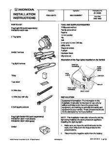
INSTALLATION INSTRUCTIONS PARTS LIST Security System: P/N 08E51-S84-100
Application
Publications No.
AII 24637 SECURITY SYSTEM
INSIGHT
Issue Date
OCT 2002
Attachment Kit: P/N 08E55-S3Y-100
Security system harness 2 Remote transmitters
Control unit
Control unit bracket
LED
Wire tie with clip
Push nut Relay 2-Pin connector (for LED)
Disarm switch Flange bolt, 6 mm
Window decal
Flange nut, 6 mm
3-Pin connector (for disarm switch)
2 Long wire ties
Nut, 12 mm
2 Short wire ties
Washer Owner’s Manual
2 Washer-screws, 4 x 30 mm
© 2002 American Honda Motor Co., Inc. - All Rights Reserved.
Cushion tape
Fuse label
AII 24637 (0210)
08E55-S3Y-1000-91
1 of 7
TOOLS AND SUPPLIES REQUIRED Small flat-tip screwdriver #2 Phillips screwdriver 10 mm Combination wrench Eye protection (face shield, safety goggles, etc.) Center punch Drill 3 mm, 5.5 mm, and 12 mm Drill bits Torque wrench File Felt-tip pen Ratchet 10 mm Socket Tape measure Diagonal cutters
Sensitivity Adjustment Knob: •
Adjust the sensitivity only if the customer requests it; the sensitivity adjustment of the glass breakage sensor is factory-set.
•
Be careful when you adjust the sensitivity; if you raise the sensitivity too much, the security system can give a false alarm. If the sensitivity is too low, the security system may not work, even if glass is broken.
INSTALLATION Customer Information: The information in this installation instruction is intended for use only by skilled technicians who have the proper tools, equipment, and training to correctly and safely add equipment to your car. These procedures should not be attempted by “do-it-yourselfers.”
Adjusting the Control Unit Use a small flat-tip screwdriver to change the mode switch, the horn/siren switch, and to adjust the sensitivity. The horn/siren switch must be set in the “HORN” position. GLASS BREAKAGE SENSOR
1.
Write down the frequencies for the radio station preset buttons.
2.
Disconnect the negative cable from the battery.
3.
Using a small flat-tip screwdriver, gently remove the two blank covers. Be careful not to damage the dashboard.
MODE SWITCH
SENSITIVITY ADJUSTMENT KNOB
AUTO LOCK AUTO MANUAL
MIN MAX
SIREN HORN
BLANK COVER (Reuse.)
Mode Switch: •
Set the mode switch according to the customer’s choice.
•
Refer to the Owner’s Manual for the explanation of each mode.
Glass Breakage Sensor: Do not attach anything like scotch tape over the holes; this is the microphone pickup. 2 of 7
AII 24637 (0210)
© 2002 American Honda Motor Co., Inc. - All Rights Reserved.
4.
Remove the pocket by lifting it up toward you.
6.
Get the control unit bracket and relay. Install the relay on the control unit bracket (one 6 mm flange bolt and one 6 mm flange nut). Tighten securely. 6 mm FLANGE NUT
6 mm FLANGE BOLT
POCKET
5.
CONTROL UNIT BRACKET
Remove the keyless entry control unit (two bolts), and unplug the connector. BOLT (Reuse.)
RELAY
7.
Install the control unit on the control unit bracket (two 4 x 30 mm washer-screws). 4 x 30 mm WASHER-SCREW
CONTROL UNIT
KEYLESS ENTRY CONTROL UNIT CONNECTOR
ANTENNA
WIRE TIE WITH CLIP CONTROL UNIT BRACKET
8.
© 2002 American Honda Motor Co., Inc. - All Rights Reserved.
AII 24637 (0210)
Attach the wire tie with clip to the antenna of the control unit, then push the clip into the hole in the control unit bracket. Cut off the excess wire tie.
3 of 7
9.
Turn the keyless entry control unit around from its original position, and mount the control unit bracket and keyless entry control unit using the two bolts you removed in step 5.
11. Loosen the four flange nuts that secure the steering column bracket, and lower the steering column. Do not remove the flange nuts.
BOLT (reused)
UPPER STEERING COLUMN COVER
STEERING BRACKET
FLANGE NUTS (4) (Loosen, but do not remove.)
KEYLESS ENTRY CONTROL UNIT (Turn around from its original position.)
CONTROL UNIT BRACKET
12. Remove the upper steering column cover by rocking the steering column up and down as required.
10. Remove the lower steering column cover (three screws and six clips). Use a shop towel around a small flat-tip screwdriver to release the six retaining clips.
13. Measure and mark the left side of the lower steering column cover. LOWER STEERING COLUMN COVER
UPPER STEERING COLUMN COVER RETAINING CLIPS ON UPPER STEERING COLUMN COVER (4) 50 mm
10 mm 12 mm DRILL BIT
LOWER STEERING COLUMN COVER
RETAINING CLIPS ON LOWER STEERING COLUMN COVER (2)
14. While wearing eye protection, lightly center-punch the mark, and drill a 12 mm hole:
SCREW (Reuse.)
4 of 7
AII 24637 (0210)
•
First drill a pilot hole with a 3 mm bit, then finish with a 12 mm bit.
•
Remove all burrs.
© 2002 American Honda Motor Co., Inc. - All Rights Reserved.
15. Route the terminal ends of the disarm switch through the hole you just drilled in the lower steering column cover, and secure the disarm switch with the washer and the 12 mm nut from the kit.
19. Route the terminal ends of the LED through the hole you just drilled in the upper steering column cover, and secure the LED with the push nut. Install the push nut securely. UPPER STEERING COLUMN COVER
LOWER STEERING COLUMN COVER
LED
2-PIN CONNECTOR
12 mm NUT WASHER
WHITE WIRE
DISARM SWITCH
3-PIN CONNECTOR
PUSH NUT
BLUE WIRE LOCK
RED WIRE
PUSH NUT
2-PIN CONNECTOR
20. Get the 2-pin connector included in the kit. Firmly push the LED terminals into the 2-pin connector until they click into position, then lower the lock.
BLACK WIRE
16. Get the 3-pin connector included in the kit. Firmly push the disarm switch terminals into the 3-pin connector until they click into position, then lower the lock.
21. Reinstall the upper steering column cover with the 2-pin connector on the left side of the steering wheel. Rock the steering column up and down as required for access.
17. Measure and mark the inside of the upper steering column cover. UPPER STEERING COLUMN COVER
UPPER STEERING COLUMN COVER 5.5 mm DRILL BIT
CENTER OF THE UPPER STEERING COLUMN COVER
SHORT WIRE TIE
LED HARNESS (Route in front of the vehicle wire harness.)
42 mm
18. While wearing eye protection, lightly center-punch the mark, and drill a 5.5 mm hole through the center-punched mark. Remove all burrs. © 2002 American Honda Motor Co., Inc. - All Rights Reserved.
VEHICLE HARNESS FRONT
22. Secure the LED harness to the vehicle harness with one short wire tie. Cut off the excess wire tie.
AII 24637 (0210)
5 of 7
23. Torque the four flange nuts you loosened in step 11 to 10 to 16 N·m (7 to 12 lb-ft).
29. Connect the disarm switch and LED harness connectors to the security system harness 2-pin and 3-pin connectors.
FLANGE NUTS (4) (Torque to 10 to 16 N·m (7 to 12 lb-ft).)
DISARM SWITCH
LOWER STEERING COLUMN COVER
DISARM SWITCH
LED
SECURITY SYSTEM HARNESS
CUSHION TAPE
SCREWS (3) (reused)
24. Reinstall the lower steering column cover by spreading the cover open to avoid breaking the disarm switch. Reinstall the three screws.
2-PIN AND 3-PIN CONNECTOR
25. Attach the two fuse labels to the fuse case on the security system harness, then push the fuse case clip into the hole in the control unit bracket. KEYLESS ENTRY CONTROL UNIT 18-PIN CONNECTOR
30. Secure the 2-pin and 3-pin connectors to the knee bolster with the cushion tape in the area shown. 31. Secure the security system harness to the vehicle harness with two long wire ties and one short wire tie.
CONTROL UNIT BRACKET CONTROL UNIT
SHORT WIRE TIE LONG WIRE TIE
22-PIN CONNECTOR FUSE CASE
RELAY
FUSE LABELS (OPTION 3A) SECURITY SYSTEM 18-PIN CONNECTOR VEHICLE HARNESS 18-PIN CONNECTOR
LONG WIRE TIE
6-PIN CONNECTOR SECURITY SYSTEM HARNESS
CLIP SECURITY SYSTEM HARNESS
26. Plug the security system harness 6-pin connector into the relay you installed in step 6. 27. Plug the sceurity system harness 18-pin connector in between the keyless entry control unit and the vehicle 18-pin connector.
32. Check that all wire harnesses are routed properly and all connectors are plugged in. 33. Reinstall the pocket and the switch covers. 34. Reconnect the negative cable to the battery, and reset the radio station presets.
28. Plug the security system harness 22-pin connector into the control unit. 6 of 7
AII 24637 (0210)
© 2002 American Honda Motor Co., Inc. - All Rights Reserved.
35. Check the operation of the security system as described in the Owner’s Manual supplied. NOTE: The remote transmitters that came with the vehicle will not arm the security system; use the new remote transmitters included with the security system. 36. Do the idle learn procedure. – Make sure all electrical items are turned off. – Start the engine. Hold the engine speed at 3,000 rpm with no load (in Park or Neutral) until the radiator fan comes on. – Let the engine idle for about 5 minutes with the throttle fully closed and with all electrical items off. NOTE: If the radiator fan comes on during this step, the time when it is operating must not be included in the 5 minutes.
© 2002 American Honda Motor Co., Inc. - All Rights Reserved.
AII 24637 (0210)
7 of 7