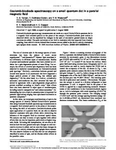
APPLIED PHYSICS LETTERS 91, 051107 共2007兲
All-optical format conversion using a periodically poled lithium niobate waveguide and a reflective semiconductor optical amplifier Jian Wang,a兲 Junqiang Sun,b兲 Qizhen Sun, Dalin Wang, Minjuan Zhou, Xinliang Zhang, and Dexiu Huang Wuhan National Laboratory for Optoelectronics, School of Optoelectronic Science and Engineering, Huazhong University of Science and Technology, Wuhan, 430074 Hubei, People’s Republic of China
M. M. Fejer Edward L. Ginzton Laboratory, Stanford University, Stanford, California 94305
共Received 21 March 2007; accepted 28 June 2007; published online 31 July 2007兲 In the present letter, the authors report on the realization of all-optical format conversion by using the cascaded sum- and difference-frequency generation in a periodically poled lithium niobate waveguide and the active mode locking in a reflective-semiconductor-optical-amplifier-based fiber ring laser. Tunable format conversions from nonreturn-to-zero pseudorandom binary sequence 共PRBS兲 signal to return-to-zero PRBS idler at 10 and 20 Gbit/ s are observed in the experiment. © 2007 American Institute of Physics. 关DOI: 10.1063/1.2761513兴 Quasiphase matched 共QPM兲 periodically poled lithium niobate 共PPLN兲 waveguide has attracted considerable interest in high-speed all-optical signal processing due to its distinct advantages of high nonlinear coefficient, ultrafast nonlinear optical response, no excess noise, and versatile second-order nonlinearities and their cascading.1 During the past few years, various nonlinear applications including efficient all-optical wavelength conversions,2–7 optical pulse compression,8 and all-optical logic gates9–12 have been proposed and demonstrated based on the PPLN waveguides. Typically, these previous researches mostly focused on the nonlinear interactions between either continuous-wave 共cw兲 lights2,3 or pulsed lights,4–7 or data streams.10,11 Recently, we have suggested and numerically simulated a PPLN-based application of all-optical format conversion by employing a data stream and a pulsed light.13,14 Note that, owing to the capability of connecting different networks which employ various data formats with each other, all-optical format conversion is also regarded as one of the important functions for future reconfigurable all-optical networks. For example, alloptical format conversion between nonreturn-to-zero 共NRZ兲 and return-to-zero 共RZ兲 is an important interface technology for future optical networks that employ both wavelengthdivision-multiplexing and optical-time-division-multiplexing technologies. However, the experimental demonstration on PPLN-based all-optical format conversion has not yet been reported up to now. In this letter, we propose and experimentally demonstrate a scheme to perform all-optical format conversion from NRZ to RZ by using a PPLN waveguide and a reflective semiconductor optical amplifier 共RSOA兲. With the pulsed optical clock generated from the RSOAbased actively mode-locked fiber ring laser 共AMLFRL兲, based on the cascaded sum- and difference-frequency generation 共cSFG/DFG兲 between NRZ signal and such optical clock in the PPLN waveguide, 10 and 20 Gbit/ s tunable NRZ-to-RZ format conversions for the pseudorandom binary sequence 共PRBS兲 NRZ signal are observed in the experiment. a兲
Electronic mail:
[email protected] Eletronic mail:
[email protected]
b兲
Figure 1 schematically shows the experimental setup for PPLN+ RSOA-based all-optical format conversion, which can be divided into four parts 共I–IV兲: the NRZ signal generator, the NRZ-to-pseudoreturn-to-zero 共PRZ兲 converter, the all-optical clock recovery unit, and the NRZ-to-RZ converter. In part I, the NRZ signal is generated by using a tunable laser 共TL兲, a Mach-Zehnder modulator 共MZM兲, a bit pattern generator 共BPG兲, a tunable frequency synthesizer 共TFS兲, and an erbium-doped fiber amplifier 共EDFA1兲. In order to clearly observe the bit patterns for NRZ-to-RZ format conversion later in the experiment, 27 – 1 PRBS NRZ signal is employed. In part II, the PRBS NRZ signal with weak clock components is converted into PRZ signal to enhance the clock components by using a fiber delay interferometer 共FDI兲. The FDI is constructed with two 3 dB couplers 共C2 and C3兲 and two fiber arms with a length difference of 5.2 mm, resulting in a time delay of 25 ps 共⌬t兲. The operation temperature of the lower arm is controlled by a temperature controlling block 共TCB兲 to adjust the phase shift 共⌬兲. Such a simple FDI can perform NRZ-to-PRZ format conversion for 10 and 20 Gbit/ s NRZ signals. In part III, the alloptical clock recovery from PRZ signal with enhanced clock components is able to be achieved easily using a RSOAbased AMLFRL. The AMLFRL consists of a variable optical attenuator 共VOA1兲, a 3 dB coupler 共C5兲, a polarization controller 共PC1兲, a RSOA with better modulation performance compared with conventional SOA, a circulator, a tunable delay line 共TDL1兲, an isolator 共ISO兲, a tunable filter 共TF1兲, and a 10:90 coupler 共C6兲. The PRZ signal is injected into the fiber ring laser with its power controlled by VOA1. The gain of the ring cavity is provided by a 1000 m strained, multiquantum-well 共MQW兲 InGaAsP–InP material RSOA. Its small-signal gain is 18 dB with the peak gain wavelength at 1550 nm when biased at 200 mW. The isolator is used to ensure the unidirectional oscillation in the ring cavity. TF1 with a 3 dB bandwidth of 1 nm is used to select the wavelength of the recovered optical clock. The length of the ring cavity can be changed by tuning TDL1. By carefully adjusting VOA1, PC1, and TFS or TDL1 in the ring cavity, it is possible to generate stable optical clock. In part IV, the extracted optical clock serving as the pulsed pump 共 P兲, together with the input NRZ signal 共S兲 and cw control 共C兲
0003-6951/2007/91共5兲/051107/3/$23.00 91, 051107-1 © 2007 American Institute of Physics Downloaded 05 Aug 2007 to 202.114.3.148. Redistribution subject to AIP license or copyright, see http://apl.aip.org/apl/copyright.jsp
051107-2
Wang et al.
Appl. Phys. Lett. 91, 051107 共2007兲
FIG. 1. 共Color online兲 Schematic diagram of the experimental setup for PPLN+ RSOA-based all-optical NRZto-RZ format conversion.
emitted from the external cavity laser 共ECL兲 are combined by a 3 ⫻ 1 coupler 共C7兲, amplified by a high-power EDFA 共HP-EDFA兲 with a small-signal gain of 40 dB and a saturation output power of 30 dBm, and then launched into the PPLN waveguide to participate in the cSFG/DFG nonlinear interactions. During the cSFG/DFG processes, the NRZ signal and the pump optical clock are used to yield the sumfrequency wave under the SFG QPM condition. At the same time, the cw control interacts with the sum-frequency wave to generate the idler wave through the subsequent DFG process. Note that the converted idler can be obtained only when all the three waves 共NRZ signal, pump optical clock, and cw control兲 are present, which corresponds to the NRZ-to-RZ format conversion from the signal wave to the idler wave. A 50-mm-long PPLN waveguide fabricated by the electric-field poling method and annealing proton-exchanged 共APE兲 technique is used in the experiment. It has a microdomain period of 14.7 m, a waveguide width of 12 m, an initial proton exchange depth of 0.8 m, and a QPM wavelength of 1543.2 nm at room temperature. The fiber-to-fiber coupling loss of the PPLN waveguide is estimated at about 4.7 dB due to the reflection losses at the uncoated end faces, mode mismatching between the fibers and the waveguide, and intrinsic waveguide losses. PC2 is used to adjust the polarization state of input optical waves before entering into the PPLN waveguide. TDL2 is employed to adjust the time delay between the NRZ signal and the pump optical clock. The optical spectra are monitored by an optical spectrum analyzer 共OSA, Anritsu MS9710C兲 with the highest spectral resolution of 0.05 nm, and the bit patterns are observed through a communications signal analyzer 共CSA, Tektronix 8000B兲. Figure 2 depicts the measured optical spectra for NRZto-PRZ format conversion. As shown in Fig. 2共a兲, it is found that the FDI acts as a comb filter which has a wavelength spacing of 0.32 nm. In the experiment, the operation temperature of the FDI is properly controlled so as to move one notch aiming at the center wavelength of the input NRZ signals. As a result, 10 and 20 Gbit/ s input NRZ signals, as shown in Figs. 2共b兲 and 2共d兲, are respectively, converted into the corresponding PRZ signals after passing through the FDI, which can be seen from Figs. 2共c兲 and 2共e兲. Remarkably, there appear two main modes with the mode spacings of 0.08 nm 共10 GHz兲 for 10 Gbit/ s in Fig. 2共c兲 and 0.16 nm 共20 GHz兲 for 20 Gbit/ s in Fig. 2共e兲 in the optical spectra of converted PRZ signals. Thus the clock components can be
greatly enhanced with the help of the NRZ-to-PRZ format conversion. Figure 3 illustrates the measured optical spectra for cSFG/DFG-based NRZ-to-RZ format conversion at 10 Gbit/ s. The wavelength of the input NRZ signal is tuned at 1546.8 nm. The wavelength of the pump optical clock is adjusted at 1539.3 nm by tuning TF1 in the AMLFRL in order to satisfy the SFG QPM condition. As shown in Fig. 3共a兲, when the control wavelength is tuned at 1550.8 nm, the new generated RZ idler wave can be obtained at 1535.5 nm. Additionally, as can be seen from Fig. 3共b兲, even for a fixed input NRZ signal, it is possible to change the wavelength of the converted RZ idler simply by the variation of the cw control wavelength. According to the previous theoretical analyses,13 the output RZ idler can be tuned in a wide wavelength range larger than 60 nm. Thus tunable operation of NRZ-to-RZ format conversion can be easily performed. To further confirm the PPLN+ RSOA-based NRZ-to-RZ format conversion, the bit patterns for different optical waves 共27 – 1 PRBS兲 are observed. As shown in Fig. 4共a兲, R1–R4, respectively, represent 10 Gbit/ s input PRBS NRZ signal 共point A in Fig. 1兲, PRZ signal 共point B in Fig. 1兲, pump optical clock 共point C in Fig. 1兲, and output RZ idler corre-
FIG. 2. 共Color online兲 Measured optical spectra for NRZ-to-PRZ format conversion. 共a兲 Transmission spectrum of FDI and the resulting specta of 关共b兲 and 共d兲兴 NRZ and 关共c兲 and 共e兲兴 PRZ at 关共b兲 and 共c兲兴 10 Gbit/ s and 关共d兲 and 共e兲兴 20 Gbit/ s. Downloaded 05 Aug 2007 to 202.114.3.148. Redistribution subject to AIP license or copyright, see http://apl.aip.org/apl/copyright.jsp
051107-3
Appl. Phys. Lett. 91, 051107 共2007兲
Wang et al.
FIG. 3. 共Color online兲 Measured optical spectra for cSFG/DFG-based NRZto-RZ format conversion at 10 Gbit/ s. 共a兲 cw control is tuned at 1550.8 nm. 共b兲 Tunable operation under different control wavelengths of 1549.4, 1550.2, 1551.0, 1551.6, and 1552.4 nm.
sponding to Fig. 3共a兲. It is apparent that, NRZ-to-PRZ format conversion 共R1 and R2兲, all-optical clock recovery 共R2 and R3兲, and NRZ-to-RZ format conversion 共R1 and R4兲 are all implemented. Figure 4共b兲 illustrates the tunable NRZ-to-RZ
format conversion at 10 Gbit/ s. R5–R9 plot the bit patterns for tunable output RZ idlers corresponding to Fig. 3共b兲 under different control wavelengths of 1549.4, 1550.2, 1551.0, 1551.6, and 1552.4 nm, respectively. No obvious changes are observed during the tuning process. The scales in Figs. 4共a兲 and 4共b兲 are 500.0 ps/ division. Figure 4共c兲 shows the bit patterns for NRZ-to-RZ format conversion operating at 20 Gbit/ s. The scale in Fig. 4共c兲 is 200.0 ps/ division. R10– R13 depict 20 Gbit/ s input PRBS NRZ signal 共point A in Fig. 1兲, PRZ signal 共point B in Fig. 1兲, pump optical clock 共point C in Fig. 1兲, and output RZ idler, respectively. It can be clearly seen that 20 Gbit/ s NRZ-to-RZ format conversion 共R10 and R13兲 is also realized with the proposed scheme. With further improvement, two future potential applications can also be implemented with our proposed scheme. First, it is possible to perform tunable multicasting NRZto-RZ format conversion simply by employing multiple cw control waves. Second, it is worth noting that the NRZ differential phase-shift keying 共DPSK兲 signal can also be converted into PRZ signal using the FDI,15 which provides the possibility of performing NRZ-DPSK-to-RZ-DPSK format conversion. These PPLN-based all-optical format conversions are attractive for all-optical signal processing and may find wide applications for future all-optical networks. In conclusion, a scheme of all-optical format conversion from NRZ to RZ at 10 and 20 Gbit/ s is proposed and demonstrated by using a PPLN waveguide and a RSOA. An FDI is introduced to perform NRZ-to-PRZ format conversion for the purpose of enhancing the clock components. The RSOAbased AMLFRL is utilized to generate the pulsed pump optical clock. The PPLN waveguide is used to complete the NRZ-to-RZ format conversion based on the cSFG/DFG nonlinear interactions. The results imply that tunable operation can be realized simply by changing the cw control wavelength. This work was supported by the National Natural Science Foundation of China under Grant No. 60577006, and by the program for New Century Excellent Talents in University 共NCET-04-0694兲. The authors would like to thank Y. Yu and J. Xu for their helpful discussions. 1
C. Langrock, S. Kumar, J. E. McGeehan, A. E. Willner, and M. M. Fejer, J. Lightwave Technol. 24, 2597 共2006兲. 2 C. Q. Xu, H. Okayama, and M. Kawahara, Appl. Phys. Lett. 63, 3559 共1993兲. 3 K. Gallo, G. Assanto, and G. I. Stegeman, Appl. Phys. Lett. 71, 1020 共1997兲. 4 G. P. Banfi, P. K. Datta, V. Degiorgio, and D. Fortusini, Appl. Phys. Lett. 73, 136 共1998兲. 5 I. Cristiani, G. P. Banfi, V. Degiorgio, and L. Tartara, Appl. Phys. Lett. 75, 1198 共1999兲. 6 J. Wang, J. Q. Sun, J. R. Kurz, and M. M. Fejer, IEEE Photonics Technol. Lett. 18, 2093 共2006兲. 7 J. Wang, J. Q. Sun, C. H. Luo, and Q. Z. Sun, Appl. Phys. B: Lasers Opt. 83, 543 共2006兲. 8 S. Ashihara, T. Shimura, K. Kuroda, N. E. Yu, S. Kurimura, K. Kitamura, FIG. 4. 共Color online兲 Measured bit patterns for 10 and 20 Gbit/ s tunable M. Cha, and T. Taira, Appl. Phys. Lett. 84, 1055 共2004兲. 9 NRZ-to-RZ format conversion. 共a兲 10 Gbit/ s NRZ-to-RZ format conversion J. Wang, J. Sun, and Q. Sun, Opt. Lett. 31, 1711 共2006兲. 10 J. Wang, J. Q. Sun, and Q. Z. Sun, Opt. Express 15, 1690 共2007兲. corresponding to Fig. 3共a兲. R1: input NRZ signal at point A in Fig. 1. R2: 11 J. Wang, J. Q. Sun, and Q. Z. Sun, IEEE Photonics Technol. Lett. 19, 541 PRZ signal at point B in Fig. 1. R3: pump optical clock at point C in Fig. 1. 共2007兲. and R4: output RZ idler with the control wavelength set at 1550.8 nm. 共b兲 12 J. Q. Sun and J. Wang, Opt. Commun. 267, 187 共2006兲. Tunable operation at 10 Gbit/ s corresponding to Fig. 3共b兲. R5–R9: tunable 13 J. Wang, J. Q. Sun, Q. Z. Sun, D. L. Wang, and D. X. Huang, Opt. Express output RZ idlers with different control wavelengths of 1549.4, 1550.2, 15, 583 共2007兲. 1551.0, 1551.6, and 1552.4 nm, respectively. 共c兲 20 Gbit/ s NRZ-to-RZ for14 J. Wang, J. Q. Sun, and Q. Z. Sun, Opt. Lett. 32, 1477 共2007兲. mat conversion. R10: input NRZ signal at point A in Fig. 1. R11: PRZ signal 15 Y. Yu, X. L. Zhang, and D. X. Huang, IEEE Photonics Technol. Lett. 18, at point B in Fig. 1. R12: pump optical clock at point C in Fig. 1. R13: 2356 共2006兲. output RZ idler with the control wavelength set at 1551.2 nm. Downloaded 05 Aug 2007 to 202.114.3.148. Redistribution subject to AIP license or copyright, see http://apl.aip.org/apl/copyright.jsp