Altair Descent and Ascent Reference Trajectory Design and Initial Dispersion Analyses Larry D. Kos and Tara T. Polsgrove Marshall Space Flight Center, Mail Code ED04 Huntsville, AL 35812
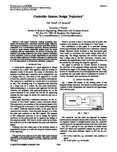
[email protected] 256-544-1522 Ronald R. Sostaric, Ellen M. Braden and Jacob J. Sullivan Johnson Space Center, Mail Code EG Houston, TX 77058 Thanh T. Le Engineering and Science Contract Group / Johnson Space Center Webster, TX 77598 The Altair Lunar Lander is the linchpin in the Constellation Program (CxP) for human return to the Moon. Altair is delivered to low Earth orbit (LEO) by the Ares V heavy lift launch vehicle, and after subsequent docking with Orion in LEO, the Altair/Orion stack is delivered through translunar injection (TLI). The Altair/Orion stack separating from the Earth departure stage (EDS) shortly after TLI and continues the flight to the Moon as a single stack. Altair performs the lunar orbit insertion (LOI) maneuver, targeting a 100-km circular orbit. This orbit will be a polar orbit for missions landing near the lunar South Pole. After spending nearly 24 hours in low lunar orbit (LLO), the lander undocks from Orion and performs a series of small maneuvers to set up for descending to the lunar surface. This descent begins with a small deorbit insertion (DOI) maneuver, putting the lander on an orbit that has a perilune of 15.24 km (50,000 ft), the altitude where the actual powered descent initiation (PDI) commences. At liftoff from Earth, Altair has a mass of 45 metric tons (mt). However after LOI (without Orion attached), the lander mass is slightly less than 33 mt at PDI. The lander currently has a single descent module main engine, with TBD lb f thrust (TBD N), providing a thrust-to-weight ratio of approximately TBD Earth g’s at PDI. LDAC-3 (Lander design and analysis cycle #3) is the most recently closed design sizing and mass properties iteration. Upgrades for loss of crew (LDAC-2) and loss of mission (LDAC-3) have been incorporated into the lander baseline design (and its Master Equipment List). Also, recently, Altair has been working requirements analyses (LRAC-1). All nominal data here are from the LDAC-3 analysis cycle. All dispersions results here are from LRAC-1 analyses. Descent Phase There are three subphases comprising the descent phase of the Altair mission: the braking burn (BB), the approach, and terminal (note a short pitch-up maneuver will be executed near the beginning of approach). The descent subphases are depicted shown in Figure 1. Implicit guidance algorithms will be used to design the reference trajectories in all these descent subphases. In this approach, we can define, in advance of the mission, a reference trajectory as a vector polynomial function of time that evolves backward from the target state. But the reference trajectory cannot be expected to intersect the initial state of the vehicle due
to navigation and control dispersions. Implicit guidance will generate acceleration commands that consist of that computed using the reference trajectory plus two feedback terms. The first “feedback” acceleration correction is proportional to the difference between the actual and reference vehicle’s positions. The second term is proportional to the difference between the actual and reference vehicle’s velocities. Implicit guidance algorithm will “drive” the vehicle to achieve the target state in the presences of controller errors, navigation state estimation error and possible re-designation of the landing site. The braking burn starts at the descent orbit perilune altitude of 15.24 km with the descent module (DM) main engine aligned with the lander’s velocity vector. It is done at TBD% thrust to remove the orbital energy at the highest efficiency possible, but not at full thrust to allow for thrust margin between the BB set throttle and the maximum available engine power. When the braking burn is completed, the lander will perform the pitch-up maneuver. The “nearly vertical” attitude of the lander will provide the crew with better visibility to detect terrain hazards surrounding the landing site. Re-designation of the landing target can then be performed after the pitch-up is completed. In the approach subphase, the throttle will vary between 60% and 40% full engine power (i.e. thrust). The direction of thrust also varies to track the reference trajectory selected for the approach phase. There will be a hazard detection sensor carried onboard Altair. This critical function will be performed during the approach phase. Using data provided by the hazard detection sensor system, the crew will have to make a decision on the possible need to redesignate a “safer” landing site. The approach subphase ends at 30 meters vertically above the final (selected) touchdown site. A very important factor in this subphase is viewing (both crew look angles and terrain hazard detection sensor viewing). The terminal subphase is intended to be a quiescent, controlled, vertical descent for 30 seconds at a constant 1 m/s velocity, until its time to shut down the DM engine. This shutdown is intended to occur at 1 meter above the surface. This means the touchdown velocity could be as high as 2.1 m/s.
FIGURE 1 -- LUNAR DESCENT SUBPHASES 2
The mission delta velocities (Vs) are tabulated in Table 1. The total main propulsion system (MPS) descent V for the piloted missions is TBD m/s (TBD m/s for cargo), while the current reaction control subsystem (RCS) budget V is TBD m/s. The main engine first lights up for the LOI burn (up to three LOI burns for non-polar sites). It will then perform the LLO plane change maneuver (when doing polar missions, if necessary). The final burn is the continuous descent and landing burn until shutdown at an altitude of 1 m. There are many small trajectory tuning maneuvers, as well as other RCS propellant usage for attitude control, all done with the RCS thrusters. The LOI burn V budget for polar missions is 891 m/s, with the global access LOI 3-burn total currently bought in at 950 m/s. The cargo LOI burn is 889 m/s due to smaller g-losses during LOI (better T/W ratio). The descent V budget currently also includes values for a small redesignation capability and a placeholder dispersions V budget estimates using experience from Apollo 11. TABLE 1 -- ALTAIR DESCENT MODULE VS
The first iteration of the descent dispersions analysis was performed during LRAC-1 to begin affirming the V value documented in the CxP descent V requirements. The tool utilized in this work is the ANTARES simulation code (Advanced NASA Technology ARchitecture for Exploration Studies ). The approach used was to first disperse one variable at a time. The variables that are currently captured in the “to disperse” list include DM main engine (ME) thrust, ME specific impulse ( I sp), propellant mass, c.m. locations (x, y, z) and inertia properties ( I xx, I yy, I zz, I xy, I xz, I yz). Additional variables will be added to the dispersions list as the model is further developed. The results from each individual contribution were root-sum-squared together to provide an interim estimate of total dispersion. This value came out to be TBD m/s. Note that with a subset of the variables that could possibly be dispersed, this value is less than the Apollo 11/Apollo 12 value in the V table above. Future work includes dispersing all parameters together in one Monte Carlo exercise. 3
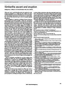
Ascent Phase The ascent phase, also comprised of three subphases, is performed by only the Altair ascent module (AM). These three are the vertical rise, the single axis rotation (SAR), and the PEG (powered explicit guidance) subphases. Each of these has a particular purpose in flight and are depicted in Figure 2. The vertical rise subphase is to immediately get the lander to a sufficient altitude to allow clearing of local terrain in the subsequent subphases. Although the AM is flying directly against (lunar) gravity to a height of approximately 100 m, which is quite an inefficient way to fly, it is only for a short time -- not more than 10 seconds. The single axis rotation (SAR) maneuver subphase is to get the AM over to the desired flight V can be path angle as quickly as possible. This is desired so that the subsequent ascent minimized. The earlier in the ascent the SAR is completed, the sooner the optimal flight path can be attained. This subphase is less than 15 seconds (currently TBD s), allowing PEG to be engaged at approximately TBD seconds after lunar liftoff. The powered explicit guidance (PEG) subphase is then flown until the AM hits its main engine cutoff (MECO) targets (the AM state at MECO). The current AM flight times to MECO are TBD sec for both the Outpost and Sortie missions, so PEG is flying the last TBD seconds of the ascent trajectory. PEG is attempting to minimize the AM propellant required (e.g. the V as well), so a significant majority of the ascent is optimally controlled.
FIGURE 2 -- ASCENT TRAJECTORY SCHEMATIC
Ascent dispersions were also run during LRAC-1. Again these analyses were performed by dispersing one variable at a time. The variables studied in this analysis included AM main engine (ME) thrust, AM ME specific impulse, and AM initial (propellant) mass. The results from each individual variable was root-sum-squared together to provide an interim total dispersion. This value came out to be TBD m/s. Note that this is only a subset of the variables that could possibly be dispersed. This effort was done using the Simulation and Optimization of Rocket Trajectories (SORT) trajectory tool. The next analysis cycle will have this analyses included in the ANTARES simulation development with results reported. As with the descent, future work will involve dispersing all parameters simultaneously.
4
Rendezvous, Proximity Operations and Docking Phase As the name implies, the Rendezvous, Proximity Operations, and Docking (RPOD) phase is also comprised of three subphases. The rendezvous phase involves infrequent, discrete maneuvers with coasting phases. The proximity operations phase consists of smaller, more frequent maneuvers, and docking initiates at docking port contact. A simplified graphic of the reference trajectory is shown below in Figure 3.
FIGURE 3 -- RENDEZVOUS TRAJECTORY SCHEMATIC
To deliver the Altair back to Orion, the RPOD trajectory utilizes an R-bar approach. The rendezvous phase begins at insertion and continues until Altair acquires the R-bar. During this time, there are five maneuvers. The Corrective Combination (NCC) burn occurs 10 minutes after insertion to clean up any ascent dispersions and target the proper Terminal Phase Initiation (TPI) point. The TPI burn places Altair on a natural coasting trajectory to acquire the R-bar at a point 2 km from Orion with a purely radial (Local Vertical, Local Horizontal (LVLH) -Z) relative velocity. Between TPI and the R-bar, three Midcourse (MC) maneuvers shape the trajectory and correct any dispersions. The 2 km acquisition range was chosen as part of a trade study performed during LDAC-2. It must be noted that since the trajectory from TPI to the R-bar is a “coasting” trajectory, the Rbar acquisition distance uniquely determines the location of the TPI point in space. This, in turn, defines the required apolune achieved during ascent. The Proximity Operations phase begins at R-bar acquisition and concludes at docking port soft contact. To close the distance between the vehicles, Altair performs a series of “glide slope” maneuvers, along with two braking gates which serve to reduce the total profile time. At the conclusion of the glideslope maneuvers, Altair is delivered to a docking port-to-docking port 5
(DP-to-DP) range of 10 m with the proper range-rate for docking, thanks to natural braking from orbital mechanics. This velocity is held constant for the final 10 m until docking port contact. A summary of the major RPOD events, the time frame, translational Vs, and the apolune and perilune are provided in Table 2. TABLE 2 -- RENDEZVOUS SEQUENCE FOR ALTAIR TO ORION, 1-REV
Trajectory Event AM Lunar Liftoff Insertion / MECO Corrective Combination Terminal Phase Initiation Midcourse Corrections 1,2,3 R-bar Acquisition 1 st & 2nd Braking Gates Glide slope maneuvers, total Docking Totals:
Phase Elapsed Time, h:mm:ss
AV, Translation Maneuver
2:23:29
24.4 m/s
Resultant Apolune x Perilune
An initial analysis of the RPOD maneuver dispersions was performed as a part of the RAC-1 analysis. The tool utilized was a Linear Covariance (LinCov) analysis code. Five different dispersion sources were considered one at a time. These error sources were environment process noise (from gravity perturbations or movement within Altair), the Orion initial navigation state knowledge, RCS performance (variations in thrust and I sp), RCS misalignment, and an estimate of insertion errors from the Ascent phase. The five individual error sources were then simultaneously run to estimate the total profile V dispersion. The resultant value was TBD m/s. As part of the next analyses cycles, the dispersion sources will be updated with improved vehicle knowledge, and ANTARES simulation development will provide independent verification. Summary/Conclusions/Future work The current budget has captured all the major AV needs of the mission and is a good foundation from which to continue improving fidelity of the trajectory analyses and simulation development. The Altair lunar lander V budget estimate and the dispersions for that estimate are continuing to progress over time as the Altair Project Office (APO) Integrated Performance Team works to mature the Altair vehicle models and trajectories. Simulation work will also continue for quite some time. As flight hardware is selected, the components can be modeled in the simulation for eventual full system simulation, as well as possible hardware-in-the-loop simulation at some point in the future.
6
References: 1. Apollo Lunar Descent and Ascent Trajectories, NASA TM X-58040, March 1970 (presented at the AIAA 8th Aerospace Sciences Meeting, New York, New York, January 19-21, 1970). 2. Jaggers, Roland F., “Shuttle Powered Explicit Guidance (PEG) Algorithm”, Rockwell Space Operations Company, November 1992, JSC-26122. 3. McHenry, R.L, Brand, T.J., Long, A.D, Cockrell, B.F., Thibodeau, J.R., “Space Shuttle Ascent Guidance, Navigation, and Control”, The Journal of the Astronautical Sciences, Vol. XXVI I, No. 1, January-March, 1979. 4. Ives, D.G., “Shuttle Powered Explicit Guidance Miscellaneous Papers”, Aeroscience and Flight Mechanics Division, JSC-28774, November 1999.
7
Altair Descent and Ascent Reference Trajectory Design and Initial Dispersion Analyses Larry D. Kos 1 and Tara P. Polsgrove 2 NASA Marshall Space Flight Center, Huntsville, AL, 35812 Ronald R. Sostaric 3 , Ellen M. Brade n and Jacob J. Sullivan 5 NASA Johnson Space Center, Houston, TX, 77058 and Thanh T. Le 6 Jacobs Technology, Engineering and Science Contract Group /Johnson Space Center, Webster, TX, 77598
The Altair Lunar Lander is one element of NASA’s Constellation Program for human return to the Moon. The Altair lander is responsible for several critical maneuvers on the way to and returning from the lunar surface. Since propellant to perform these maneuvers constitutes 50% (cargo) to greater than 60% (piloted) of the total lander mass, it is important to characterize the magnitude of these maneuvers as accurately as possible early in the design process. The Altair Lander descent module main engine performs the lunar orbit insertion burn(s), the low lunar orbit plane change burn when necessary, and the powered descent burn to lunar touchdown. The descent module also performs all trajectory correction maneuvers en route using a storable reaction control system as well as all attitude control functions. The Altair ascent module main engine performs the single, continuous ascent burn from the moon after the seven-day lunar surface mission to the low lunar orbit phasing ellipse. The ascent module then performs all rendezvous, proximity operations and docking maneuvers using the ascent module reaction control system. This paper describes the Altair performance characteristics and results determined thus far from the first four design and analysis cycles and presents the results of analysis and simulation work defining the Altair vehicle’s required maneuvers as well as statistical analyses of anticipated dispersions in performance parameters.
Nomenclature
c 0 , c 1 , c2 g
= Unknown coefficients = Acceleration due to gravity, m/s 2 Isp = Specific impulse, sec KP, KD = Gain factors, scalar r 0, v 0 = Initial position and velocity rt, v t, a t = Target position, velocity and acceleration t = Time, sec tgo = Time to go, sec T/W, T/W0 = Thrust-to-Weight ratio, Initial Thrust-to-Weight, non-dimensional V = Delta velocity, m/s 1 Aerospace Engineer, Advanced Concepts Office, MSFC/ED04, Senior Member. 2 Aerospace Engineer, Advanced Concepts Office, MSFC/ED04. 3 Aerospace Engineer, Flight Mechanics and Trajectory Design Branch, JSC/EG5, Senior Member. 4 Aerospace Engineer, Flight Mechanics and Trajectory Design Branch, JSC/EG5. 5 Aerospace Engineer, GN&C Autonomous Flight Systems Branch, JSC/EG6, Member. 6 Aerospace Engineer, On-Orbit GN&C Section, Mail Stop J3-B3-2. 1 American Institute of Aeronautics and Astronautics
acmd Oerr coerr
= Commanded pitch and yaw gimbal angles, rad = Pitch and roll attitude errors, rad = Pitch and roll angular rate errors, rad/sec
I. Introduction HE Altair Lunar Lander is the linchpin in the Constellation Program (CxP) for human return to the Moon. Altair is delivered to low Earth orbit (LEO) by the Ares V heavy lift launch vehicle, and after subsequent docking with Orion in LEO, the Altair/Orion stack is delivered through trans-lunar injection (TLI). The Altair/Orion stack separates from the Ares V Earth departure stage (EDS) shortly after TLI and c ontinues the flight to the Moon as a single stack.
Figure 1. Altair Lunar Lander, Side View. The Altair Lunar Lander is comprised of an Ascent Module (top,
center), an Airlock (top, right), and a Descent Module (bottom, gold Mylar). Altair performs the lunar orbit insertion (LOI) maneuver(s), targeting a 100 -kilometer (km) circular orbit. This orbit will be a polar orbit for Outpost missions landing near the lunar South Pole and other inclinations for Global Access missions to other points on the lunar surface. After spending approximately 20 to 116 hours in low lunar orbit (LLO), the lander undocks from Orion and performs a series of small maneuvers to set up for descending to the lunar surface. This descent begins with a small descent orbit insertion (DOI) maneuver, putting the lander on an orbit that has a perilune of 15.24 km (50,000 ft), the altitude where the actual powered descent initiation (PDI) commences. The Altair design team began work in 2007 and has conducted a series of analysis cycles focusing on design and requirements maturation. With each cycle the design matures and evolves to improve reliability and compliance to program requirements. Nominal data presented here is from design and analysis cycle 4 (LDAC-4), completed June conducted during the requirements analysis cycles 1 and 2 (LRAC-1 2010. Trajectory dispersions data is from work and LRAC-2), completed in June 2009 and December 2009 respectively. Upgrades for loss of crew (LDAC-2) and loss of mission (LDAC -3) have previously been incorporated into the lander baseline design (and its Master Equipment List). All nominal data here are from the most recent LDAC-4 analysis cycle.
II. Trans-lunar Injection through Descent Orbit Insertion While active in LEO, the Altair lander is not responsible for any maneuvers until after the TLI burn is completed by the Ares V EDS. The trans-lunar cruise (TLC) phase of the mission spans the 4 days between TLI and initiation 2 American Institute of Aeronautics and Astronautics
of LOI. During this time Altair is responsible for attitude control of the Orion-Altair stack, and any trajectory correction maneuvers that may be required during transit. These maneuvers are performed by Altair’s Descent Module reaction control system (RCS). The first firing of Altair’s main engine occurs at LOI. The magnitude and quantity of LOI maneuvers required depends on the mission and landing site selection. Following LOI, the AltairOrion stack loiters in LLO for a minimum of 24 hours. This time is allocated to allow for sufficient state vector updates to enable a precision landing, and to allow for crew operations which include preparing the Orion vehicle for untended operations, preparing the Altair vehicle for descent, and a crew sleep period. During LLO loiter Altair is responsible for attitude control as well as altitude maintenance as needed. At the conclusion of the LLO loiter period, the uncrewed Orion vehicle separates and backs away from the now crewed Altair. Altair then executes a plane change maneuver if required, and the DOI maneuver. A. Trans-lunar Cruise (TLC) During the TLC the Altair will maintain a stack attitude where the Altair DM main engine and landing gear are pointed away from the Sun, and Orion’s high gain antenna is pointed toward the Earth with deadbands as high as 20 degrees. Preliminary estimates indicate that this attitude can be maintained with a small amount of propellant, possibly on the order of 6 kg/day. 1 There are four trajectory correction maneuvers (TCM) planned in the Altair nominal TLC, however it is anticipated that all four will not be executed every mission. These maneuvers are intended to correct for TLI inaccuracies, both natural and induced perturbations to the vehicle, and any navigation errors that accumulate during the transit to the moon. More information about navigation during TLC can be found in Ref. 2. The allocation of delta velocity (V) for each TCM and an anticipated schedule are given in Table 1. Actual TCMs, when required, will be performed at a magnitude and schedule that is optimized during each mission. The root-sum-square (RSS) total budget for the four TCM Vs is 25.4 m/s. Table 1. Altair TLC Trajectory Correction Maneuver V Summary.
TCM #
3
V, m/s
Time from TLI, hours
Time from LOI, hours
TCM-1
21.5
2 to 3
93 to 94
TCM-2
2.0
—24
—72
TCM-3
3.7
—62
—34
TCM-4
2.6
—88
—8
RSS Total:
25.4 m/s
B. Lunar Orbit Insertion (LOI) The LOI burn was determined by CxP Level 2 analyses. 3,4 The LOI Vs are 894 m/s for the piloted Outpost mission, 953 m/s for the Global Access Sortie mission, and 892 m/s for the Cargo mission. 3,4 LOI dispersions were determined by the same analyses which generated the TCM Vs in the previous section resulting in an additional 3 m/s to cover for various error sources. 2 At the Lunar Capability Concept Review (LCCR) in June 2008, CxP decided to allocate 950 m/s for the Global Access mission for LOI . 4 This value is a compromise between percentage of the lunar surface thatis accessible, the temporal availability of the more difficult sites, and the desire to minimize the LLO loiter duration and the LOI V requirement. The Outpost and Cargo Vs are just a resultant of the same analyses, but sized for just the South Pole location. All of these LOI Vs are intended to accommodate as many departure (TLI) and arrival (LOI) epochs as possible over the course of the 18.6-year cycle of the Moon’s inclination variation. C. Low Lunar Orbit (LLO) During the LLO loiter period, Altair is responsible for both the attitude and altitude maintenance for the Altair/Orion stack. It is important to keep the stack oriented in a solar inertial attitude so that Orion’s solar arrays are pointed toward the Sun for power generation. For Orion thermal constraints, it is desired to keep the lunar orbit altitude within a 10-km deadband about the nominal 100-km altitude. For polar missions, the loiter time will be approximately 24 hours. For global access missions, the low lunar loiter time could be up to four additional days beyond the normal 1-day LLO loiter.
American Institute of Aeronautics and Astronautics
To determine an ACS budget, a scan of different solar beta angles, lunar orbit inclinations and ascending nodes was completed. From these studies, an average propellant usage for attitude and altitude maintenance was determined. For the attitude maintenance budget, 30 kg/day was budgeted. For the altitude maintenance budget, although none is needed for a 1-day loiter, 35 kg/day was budgeted for the 5-day loiter. For the Outpost mission, it will likely be necessary to perform a LLO plane change maneuver to place the orbit plane over the landing site if the Outpost site is not located very close to the pole. The Altair lander can perform up to a 1 degree maneuver and the corresponding V budget for this maneuver is 28.5 m/s. This is done with the DM MPS system to minimize the propellant needed for the maneuver. D. Descent Orbit Insertion The descent orbit insertion burn is done using the DM RCS. The DOI maneuver drops the lander from the LLO circular orbit to an elliptical orbit with perilune much nearer the surface. This maneuver is done approximately half of an orbit from the landing point. This is done with the DM RCS to preserve the accuracy of the knowledge of the lander state to facilitate landing within the constraint of achieving 1 km accuracy at touchdown for Sortie missions (and prior to Outpost establishment ) and 100-meter accuracy for Outpost missions after it has been established. III. Descent Phase
The descent phase is one continuous burn, beginning at Powered Descent Initiation (PDI). There are three subphases comprising the descent phase of the Altair mission: the braking burn (BB), the approach, and terminal (note a short pitch-up maneuver will be executed near the beginning of approach), all shown in Figure 1. At liftoff from Earth, for the Sortie and Outpost mission, the Altair lander has a mass of 45 metric tons (mt). In LLO after separation from Orion, the lander masses are 31 mt and 32 mt at PDI, respectively. The DM main propulsion system (MPS) currently has a single descent module main engine, a nominal specific impulse (Isp) of 450.1 sec (with a minimum guaranteed Isp of 448.6 sec), with 18,627 lb f thrust (82,900 1), providing a thrust-toweight (T/W) ratio of 0.24 Earth g’s at PDI. The cargo mission masses are 54.5 mt at liftoff and 43.5 mt at PDI (Cargo T/W = 0.18 Earth g’s).
Figure 2. Lunar Descent Subphases. The descent phase is comprised of a braking burn subphase, a pitch-up maneuver, an approach subphase and a terminal descent subphase. A. Braking Burn The braking burn starts at the descent orbit perilune altitude of 15.24 km with the descent module (DM) main engine aligned with the lander’s velocity vector. It is done at 92% thrust to remove the orbital energy at the highest efficiency possible, but not at full thrust to allow for thrust margin between the BB set throttle and the maximum available engine power . Thrust margin is necessary in order be able to remove dispersions during the braking burn. 4 American Institute of Aeronautics and Astronautics
B. Pitch-up Maneuver When the braking burn is completed, the lander will perform the pitch-up maneuver. The “nearly vertical” attitude of the lander will provide the crew with better visibility to detect terrain hazards surrounding the landing site. Re-designation of the landing target can then be performed after the pitch-up is completed. C. Approach During the approach phase, the vehicle descends at a lower throttle (roughly between 60% and 40% full engine thrust) while the landing area is examined for hazards. The magnitude and direction of thrust varies to track the reference trajectory selected for the approach phase. A hazard detection sensor carried onboard is used to assist in identification of the best location in which to land. For the piloted mission, the crew will have to make a decision on the possible need to re-designate to a “safer” landing site. This function can also be carried out autonomously for a cargo mission or in case of an incapacitated crewmember. The trajectory design must account for providing a landing approach that enables adequate viewing of the landing area by the both the crew and the hazard detection system. 5-10 If a new landing location is selected, the target is updated in the GN&C software and the guidance calculates an updated trajectory that delivers the vehicle to the new location. This changes the throttle and attitude profile for the remaining portion of the phase. An additional amount of propellant is expected to be used and this has been allocated in the V budget. Redesignation can occur multiple times during the Approach Phase. Whether redesignation occurs or not, the approach subphase ends at 30 meters vertically above the final (selected) touchdown site. D. Terminal The terminal subphase is intended to be a quiescent, controlled, vertical descent for 30 seconds at a constant 1 m/s velocity over the last 30 meters of altitude. The DM engine shutdown occurs just prior to touchdown and the shutdown sequence is initiated at 1 meter above the surface. Assuming a free fall from 1-m height at -1 m/s, the expected worst case touchdown velocity is 2.1 m/s. E. Descent Dispersions The first iteration of the descent dispersions analysis was performed during LRAC-1 to begin affirming the V dispersions budget documented in the CxP descent V requirements. The tool utilized in this work is the ANTARES simulation code (Advanced NASA Technology ARchitecture for Exploration Studies). This 6-DOF simulation was developed under Altair for use in both GN&C development and performance assessment. Guidance and control algorithms, along with a perfect navigation assumption, were used. The study approach used was to first disperse one variable at a time. The variables that are currently captured in the “to disperse” list include DM main engine (DME) thrust, DME specific impulse ( I sp), propellant mass, c.m. locations (x, y, z) and inertia properties (Ixx, Iyy, Izz, Ixy, Ixz, Iyz). Additional variables will be added to the dispersions list as the model is further developed. The results from each individual contribution were RSS’d together to provide an interim estimate of total dispersion. This value came out to be 28.2 m/s. Note that with a subset of the variables that could possibly be dispersed, this value is less than the Apollo 11/Apollo 12 V value in Table 2 below. 11 Future work includes dispersing all parameters together in one Monte Carlo exercise. 12 F. Guidance Description The guidance algorithm is based on the Apollo Lunar Module Guidance. 5 During the braking and approach phases, the acceleration profile is restricted to be a quadratic equation of time. a = c 0 + c1 t + c2 t 2
(1)
Analytic equations for velocity and position can be integrated from this equation and the coefficients c 1 and c2 can solved using the initial position and velocity, v o and ro . (v + v 0 c0 = a t — )+ 12 ` 0 t 6 r go tg or
American Institute of Aeronautics and Astronautics
(2)
c= 1
6
at
(5 +6
tgo
v t +3v 0
r r ) )-48( t — 3 0 tgo tgo 2
at —12(2 v t +v 0 )+ 36 (rt —r0 ) c 2 2 = 6 2 3 4 tgo tgo tgo
(3)
(4)
The length of the burn, tgo, and the position, velocity, and acceleration targets (r t , vt , at) must be provided. These equations are solved in each axis. A new set of targets is used for each phase. G. Controller Description The control algorithm uses thrust vector control to steer the vehicle and was developed by the Autonomous Landing and Hazard Avoidance Technology (ALHAT). 6 The thrust vector control (TVC) is used to control the vehicle’s pitch and yaw. The TVC has no control authority in the roll axis. RCS jets are used to control roll. A simple proportional-derivative (PD) controller is driven by pitch and yaw attitude and angular velocity errors.
= K Perr + KDerr M
cmd
(5)
Where the commanded pitch and yaw gimbal angles, Scmd, is determined by the pitch and roll attitude errors, Θ err, and pitch and yaw angular rate errors, ω err . The two gains, KP and KD are scalars. H. Descent Module Delta Velocities (Vs) The mission Vs for the descent module are tabulated in Table 2. The total MPS descent V for the piloted missions requires 2074 m/s (2202 m/s for cargo), while the current RCS budget V requires up to 76 m/s. The main engine first lights up for the LOI burn (up to three LOI burns for non-polar sites). It will then perform the LLO plane change maneuver (when doing polar missions, if necessary). The final burn is the continuous descent Table 2. Altair Descent Module MPS and RCS V Summary.
6 American Institute of Aeronautics and Astronautics
and landing burn until shutdown at an altitude of 1 m. The descent V budget currently also includes values for a small redesignation capability and a placeholder dispersions V budget estimates using experience from Apollo 11. 11 The DME is lit as many as four times and as few as two for this stable of missions. There are many small trajectory tuning maneuvers shown in the table, as well as other RCS propellant usage for attitude control, all done with the RCS thrusters. IV. Ascent Phase
The ascent phase, also comprised of three subphases, is performed by only the Altair ascent module (AM). These three subphases are the vertical rise, the single axis rotation (SAR), and the powered explicit guidance (PEG) subphases. Each of these has a particular purpose in flight and are depicted in Figure 3. A. Vertical Rise The vertical rise subphase is to immediately get the lander to a sufficient altitude to allow clearing of local terrain in the subsequent subphases. Although the AM is flying directly against (lunar) gravity to a height of approximately 100 meters, which is quite an inefficient way to fly, it is only for a short time -- not more than 10 seconds.
Figure 3. Lunar Ascent Trajectory Schematic. The ascent phase is comprised of a vertical rise subphase, a single-axis rotation maneuver, and a powered explicit guidance (PEG) subphase. B. Single Axis Rotation The SAR maneuver is an attitude-rate and attitude-acceleration limited maneuver designed to re-orient the AM to the desired attitude for the start of the PEG phase as quickly as possible. The earlier in the ascent the SAR is completed, the sooner the optimal flight path can be attained. This subphase is less than 15 seconds (currently 11 seconds), allowing PEG to be engaged at approximately 20 seconds after lunar liftoff. The maximum and desired pitch rate during SAR is 5 degrees per second. C. Powered Explicit Guidance The PEG subphase is then flown until the AM hits its main engine cutoff (MECO) targets (the AM state at MECO). The current AM flight times to MECO are 401 sec for the Sortie mission, so PEG is flying approximately the last 380-385 seconds of the ascent trajectory. The Outpost mission has a burn time of 430 sec (~410-415 sec for PEG). PEG is attempting to minimize the AM propellant required (e.g. the V as well), so about 95% of the ascent is optimally controlled. 13,14,15 D. Ascent Module Delta Velocities (Vs) The mission Vs for the AM are tabulated in Table 3 for both the Sortie and Outpost piloted cases. The lunar ascent is a single continuous burn for the AM MPS. The AM MPS uses a 5000 lb f (24,500 N) storable propellant engine with an Isp of 320 sec, the major difference between the two cases is the different initial mass at lunar liftoff (or abort during descent) for each variation of the vehicle, thus requiring a slightly higher V done by the MPS for 7 American Institute of Aeronautics and Astronautics
the Outpost mission (Sortie T/W 0 = 0.35; Outpost T/W 0 = 0.33). The subsequent portions of the missions are nearly identical for the two cases. The V budgets for both the MPS dispersions and a lunar launch window are added to that performed by the MPS. The launch window analyses was performed for a range of launch site latitudes and target orbit inclinations. To envelope three launch opportunities (one attempt two hours prior to nominal liftoff and one atte mpt two hours after nominal liftoff), 8 m/s was determined to be necessary for the worst-case lunar surface location. Table 3. Altair Ascent Module MPS and RCS V Summary.
V. Rendezvous, Proximity Operations and Docking Phase As the name implies, the Rendezvous, Proximity Operations, and Docking (RPOD) phase is also comprised of three subphases. The rendezvous phase involves infrequent, discrete maneuvers with coasting phases. The proximity operations phase consists of smaller, more frequent maneuvers, and docking initiates at docking port contact. A simplified graphic of the reference trajectory is shown below in Figure 4. A. Rendezvous To deliver the Altair back to Orion, the RPOD trajectory utilizes an R-bar (i.e. the orbit radius vector) approach. The rendezvous phase begins at insertion and continues until Altair acquires the R-bar. During this time, there are five maneuvers. The Corrective Combination (NCC) burn occurs 10 minutes after insertion to clean up any ascent dispersions and target the proper Terminal Phase Initiation (TPI) point. This time delay should allow Altair to perform relative navigation using its star tracker and S-band communication system for post-insertion estimates of bearing and range/range-rate, respectively. The TPI burn places Altair on a natural coasting trajectory to acquire the R-bar at a point 2 km below Orion with a purely radial (Local Vertical, Local Horizontal (LVLH)-Z) relative velocity. Between TPI and the R -bar, three . Midcourse (MC) maneuvers shape the trajectory and correct any dispersions The MC burns were placed to allow the Altair Laser Imaging, Detection, and Ranging (LIDAR) system to acquire Orion between MC 2 and MC 3 . There is roughly 330 seconds between the outer edge of the LIDAR range and the MC 3 burn, which allows plenty of time for the LIDAR to acquire the target and process navigation knowledge prior to performing MC 3 . Using the improved state knowledge from the LIDAR, Altair is able to significantly reduce its dispersions (by a factor of 4 for downrange and a factor of 22 for altitude) before R-bar acquisition.
American Institute of Aeronautics and Astronautics
The 2 km acquisition range was selected as part of a trade study performed during LDAC-2. It must be noted that since the trajectory from TPI to the R-bar is a “coasting” trajectory, the R-bar acquisition distance uniquely determines the location of the TPI point in space. This, in turn, defines the required apolune achieved during ascent.
Figure 4. Rendezvous Trajectory Schematic. The RPOD phase is comprised of a rendezvous subphase, a proximity operations maneuvers, and a docking subphase.
B. Proximity Operations The Proximity Operations phase begins at R-bar acquisition and concludes at docking port soft contact. To close the distance between the vehicles, Altair performs a series of “glide slope” maneuvers, along with two braking gates, the first a 0.2 m/s burn at 100 m, and the second a 0.1 m/s burn at 50 m, which serve to reduce the total profile time by nearly 15 minutes. The distance of the vehicles at the times of the braking gates, along with the time between the second braking gate and docking, should provide enough time for any perturbations on Orion from plume impingement to dampen out. However, this assumption should be validated in the future through simulation. At the conclusion of the glideslope maneuvers, Altair is delivered to a docking port-to-docking port (DP-to-DP) range of 10 m with the proper range-rate for docking, thanks to natural braking from orbital mechanics. This velocity is held constant at -0.03 m/s for the final 10 m until docking port contact. C. Docking Altair and Orion will utilize the Low-Impact Docking System (LIDS) for docking. LIDS is a fully androgynous docking system, and is the standard for all docking in the Constellation Program. Any docking system places constraints on the contact conditions at time of docking, and LIDS is no exception. As a 3-DOF tool, Linear Covariance (LinCov) analysis is inappropriate to perform docking analysis, and the simulation was terminated at the beginning of the constant approach. A detailed analysis of Altair/Orion docking in LLO has been performed, however, and the results indicate that the current Altair configuration is able to successfully complete the docking. 16 A summary of the major RPOD events, the time frame, translational Vs, and the apolune and perilune are provided in Table 4. The total deterministic V for RPOD is 24.4 m/s.
9 American Institute of Aeronautics and Astronautics
Table 4. Altair Rendezvous Sequence for Altair to Orion (1-rev). Trajectory Event
Phase Elapsed Time, h:mm:ss
AV, Translation Maneuver
Resultant Apolune x Perilune
AM Lunar Liftoff
0:00:00
----
----
Insertion / MECO
0:06:46
----
79 x 15 km
Corrective Combination
0:16:46
1.7 m/s
86 x 14 km
Terminal Phase Initiation
1:02:56
19 m/s
99 x 85 km
1:14:19 - 1:38:04
0 m/s
99 x 85 km
1:42:04
0.4 m/s
99 x 85 km
2:07:44, 2:11:16
0.3, 0.1 m/s
100x98, 100x99 km
----
2.9 m/s
----
2:23:29
----
100 x 100 km
2:23:29
24.4 m/s
Midcourse Corrections 1, 2, 3 R-bar Acquisition 1 st & 2nd Braking Gates Glide slope maneuvers, total Docking Totals:
D. RPOD Dispersions An initial analysis of the RPOD maneuver dispersions was performed as a part of the RAC-1 analysis. The tool utilized was a LinCov analysis code. One of the outputs of the LinCov analysis is the statistical mean and standard deviation for each maneuver. To determine the sensitivity of the RPOD profile to various dispersion sources, five different dispersion sources were considered one at a time. These error sources were environment process noise (from gravity perturbations or movement within Altair), the Orion initial navigation state knowledge, RCS performance (variations in thrust and I sp), RCS misalignment, and an estimate of injection errors from a Monte Carlo simulation of the Ascent phase. Table 5. V Dispersion Analysis for Altair LLO RPOD.
10 American Institute of Aeronautics and Astronautics
The five individual error sources were then simultaneously run to estimate the total profile V dispersion. Since each burn occurs in the orbital plane, the nominal plus 3- values were summed (rather than RSS’d) to obtain a conservative estimate of total dispersion V. The resultant value was an additional 22.4 m/s above the nominal V, raising the total RPOD V budget to 47 m/s. The results of this analysis is provided in Table 5. As part of the next analyses cycles, the dispersion sources will be updated with improved vehicle knowledge, and ANTARES simulation development will provide independent verification. VI. Conclusion
The current Altair maneuver budget captures all the major V needs for this set of missions (Global Access Sortie, Outpost, Cargo) and is a good foundation from which to continue improving fidelity of the trajectory analyses and simulation development. The Altair lunar lander V budget estimate and the dispersions for that estimate will continue to mature in fidelity and accuracy over time as the Altair Project Office (APO) Integrated Performance Team develops the Altair vehicle models and trajectory simulations further. References
1 Lee, A.Y., Ely, T., Sostaric, R., Strahan, A.L., Riedel, R.E., Ingham, M., Wincentsen, J., and Sarani, S., “An Overview of the Guidance, Navigation, and Control System Design of The Lunar Lander Altair” Proceedings of the AIAA Guidance, Navigation, and Control Conference, and Exhibit, Toronto, Ontario, Canada, August 2-5, 2010. 2 Ely, T., Heyne, M., and Riedel, J.E., “Altair Navigation during Trans-Lunar Cruise, Lunar Orbit, Descent, and Landing,” Proceedings of the AIAA Guidance, Navigation, and Control Conference, and Exhibit, Toronto, Ontario, Canada, August 2–5, 2010. 3 Garn, M., Qu, M., Chrone, J., Su, P., Karlgaard, C., “NASA’s Planned Return to the Moon: Global Access and Anytime Return Requirement Implications on the Lunar Orbit Insertion Burns”, AIAA-2008-7508, AIAA Astrodynamics Specialist Conference, Honolulu, HI, August 2008. 4 “Integrated Performance and Mission Design,” Constellation Program Lunar Capability Concept Review, NASA, Houston, TX, June, 2008 (unpublished). 5 Sostaric, R.R., Rea, J.R., “Powered Descent Guidance Methods For The Moon and Mars”, AIAA-2005-6287, AIAA GN&C Conference, San Francisco, CA, August 2005. 6 Johnson, Michael C., ‘A Parameterized Approach to the Design of Lunar Lander Attitude Controllers’, AIAA-2006-6564, AIAA GN&C Conference, Keystone, CO, August 21-24,2006. 7 Paschall, S.C., Brady, T., Cohanim, B.E., Sostaric, R.R., “A Self Contained Method for Safe and Precise Landing”, IEEE Aerospace Conference, Big Sky, MT, March 1-8, 2008. 8 Davis, J.L., Striepe, S.A., Maddock, R.W., Hines, G.D., Paschall, S.C., Cohanim, B.E., Fill, T.J., Johnson, M.C., Bishop, R.H., DeMars, K.J., Sostaric, R.R., and Johnson, A.E., “Advances in POST2 End-to-End Descent and Landing Simulation for the ALHAT Project”, AIAA-2008-7508, AIAA Astrodynamics Specialist Conference, Honolulu, HI, August 2008. 9 Strahan, A.L., Law, H.G., Bilimoria, K.D., and Mueller, E.R., “A Review of Research Into GNC Performance and Interface Design for A Piloted Lunar Landing,” Proceedings of the AIAA Guidance, Navigation, and Control Conference, and Exhibit, Toronto, Ontario, Canada, August 2 –5, 2010. 10 Strahan, A.L., and Johnson, A., “Terrain Hazard Detection and Avoidance during the Descent and Landing Phase of the Lunar Lander Altair Mission,” Proceedings of the AIAA Guidance, Navigation, and Control Conference, and Exhibit, Toronto, Ontario, Canada, August 2–5, 2010. 11 Apollo Lunar Descent and Ascent Trajectories, NASA TM X-58040, March 1970 (presented at the AIAA 8th Aerospace Sciences Meeting, New York, New York, January 19-21, 1970). 12 Lee, A.Y., Strahan, A.L., Tanimoto, R., and A. Casillas, “Thrust Vector Control of the Lunar Lander Altair in the Presence of Fuel Sloshing,” Proceedings of the AIAA Guidance, Navigation, and Control Conference, and Exhibit, Toronto, Ontario, Canada, August 2–5, 2010. 13 Jaggers, Roland F., “Shuttle Powered Explicit Guidance (PEG) Algorithm”, Rockwell Space Operations Company, November 1992, JSC-26122. 14 McHenry, R.L, Brand, T.J., Long, A.D, Cockrell, B.F., Thibodeau, J.R., “Space Shuttle Ascent Guidance, Navigation, and Control”, The Journal of the Astronautical Sciences, Vol. XXVII, No. 1, January-March, 1979. 15 Ives, D.G., “Shuttle Powered Explicit Guidance Miscellaneous Papers”,Aeroscience and Flight Mechanics Division, JSC28774, November 1999. 16 Sullivan, J., Lee, A.Y., and Grover, R., “Rendezvous and Docking Sensor and Effector System Designs for the Lunar Lander Altair,” Proceedings of the AIAA Guidance, Navigation, and Control Conference, and Exhibit, Toronto, Ontario, Canada, August 2–5, 2010.
11 American Institute of Aeronautics and Astronautics
Altair Performance: Outline/Mission Phases Mission Phases/Outline:
♦ Trans-Lunar Cruise/Coast
•
TCM Vs & dispersions
•
LOI V(s) & clean-up
•
Attitude and altitude maintenance
♦ Lunar Orbit Insertion
Airl Ascent Mod Descent Mod
♦ Low Lunar Orbit Loiter ♦ Plane Change V ♦ Descent Orbit Insertion V ♦ Powered Descent
•
V & dispersions
♦ Ascent • MPS Vs & dispersion
♦ Rendezvous, Prox Ops & Docking
•
RCS Vs & dispersions
2
Altair Lunar Lander (LL) ♦ Altair -- overall L • 9.1 m x 9.6 m ♦ Airlock (AL) • 1.75 m x 2.75 m
♦ Ascent Module (A X • 2.5 m x 5 m x 5.8 ♦ Descent Module (DM); 8.2 m x 7.8 m 6.2 m..: Top View
Front View
Side View
3
Trans-Lunar Injection (TLI) & Trans-Lunar Cruise (TLC) ♦ EDS completes the TLI burn (up to ~3165 m/s + gravity-losses) and separates from the LL/Orion (CEV) ♦ TLC is between 3.7 to 4 days from TLI to Lunar Orbit Insertion (LOI) ♦ The LL/CEV stack will fly w/ the CEV-tail-to-Sun most of the time
•
•
This attitude will have the Sun at the head of the lander, with the LL partially shaded by the CEV. Due to the unknown direction the DM RCS thrusters will have to fire to perform the Trajectory Correction Maneuvers (TCMs/MCCs), the LL/CEV stack will need to alter its coasting attitude for the TCMs/MCCs, then return to the preferred coasting attitude.
Trans-Lunar Cruise/Coast Trajectory (Earth-fixed frame, Copernicus Trajectory Tool) 4
Low Lunar Orbit (LLO) & S.P. Descent Trajectory A ♦ LOI burn puts the LL/CEV into a 100 km circular orbit ~above the lunar poles ♦ After a LLO loiter of 1-5 days duration, the LL and CEV will separate • CEV will do the separation burn ♦ LL will do up to 1 ¡ plane change ~3/4 rev before descent orbit insertion (DOI)
♦
•
—20-second burn with DM main engine at 60% (not required for Cargo or Sortie DRMs)
DOI to target South Pole LZ uses the four 100-lb f axially pointing DM RCS thrusters
•
—6 minutes for the crewed mission; —9 minutes for cargo
De-orbit Burn (DOI) Low Lunar Orbit Phase 100 x 100 km
Landing Site/Zon 'N.
/
/
Transfer Orbit Coast 100 x 15.24 km
Powered Desc 5
Altair -- Baseline Separation in Polar Orbit Undocking to Landing Maneuver Sequence -- Free Return Separation Initial orbit: Polar
1: Back-away (0.0 rev) 4: DOI (2.0 rev)
Trajectory Event
Phase Elapsed Time
Active Vehicle
hh:mm:ss 3: Plane Change (1.25 rev) Equator: Moon’s Rotation: --- )0-
5: Landing (2.5 rev)
Undocking Backaway 1 Backaway 2 Separation Plane Change DOI
00:00:00 00:00:00 00:01:00 01:00:04 02:16:04 03:55:58
Orion Orion Orion Orion Altair Altair
2: Separation (0.5 rev) Aerosciences & Flight Mechanics Division Robert Merriam / JSC / EG5 / 281-483-3298
6
Lunar Descent Trajectory Phases Powered Descent Initiation (PDI)
100 km
Transfer - Orbit Phase (coast)
Powered Descent
Braking Phase h = 15,240 m (15.24 km) R = ~560,000 m (560 km)
Braking Burn Maneuver Efficiently reduce velocity from orbital speeds (92-95% throttle)
Deorbit maneuver
Pitch LIp Phase
Approach Phase h = 270 m R = 850 m
Approach Phase: • Duration = 77 sec; • 16° approach path angle
Approach Maneuver Variable duration guidance phase (HD/HI/HA)
Final Descent Phase h 0 = 30 m
Terminal Phase/fertical Descent Maneuver to Touchdown 30 sec vertical descent to surface at constant acceleration
7
Lunar Descent Guidance ♦ Algorithm based upon the Apollo Lunar Module Guidance: • Acceleration profile is modeled/restricted to a quadratic (in each axis): a =c 0 +c1 t+c 2 t
2
♦ Solve for coefficients at each guidance call • Solve for c 1 and c2 using r0 and v 0 ( tgo, rtf , vtf , a t are given) c0 = a t — 6 c1 = —6 c2 = 6
at tgo at
tgo
2
( rr — r0 ) (v t + v0 ) + 12 2 tgo tgo
+6
( 5 v t + 3 v0 )
-12
tgo
2
( 2 v t + v0 ) tgo 3
—48 ( + 36
rt — r0 ) tgo 3
a = acceleration command t = time since last guidance call tgo = time to go until end of phase v0 = current velocity r0 = current position at = acceleration target (at end of phase) vt = velocity target (at end of phase) rt = position target (at end of phase)
(rt — r0 )4 tgo
♦ At the time of each guidance call, t=0, therefore the command is equal to c 0 • c 1 and c2 only needed between guidance cycles or near end of phase
♦ Analytic expression for velocity & position can be obtained from this solution
8
ti
Lunar Descent Dispersions
♦ Initial state at Powered Descent Initiation •
PDI: -71.6 ¡ latitude, -179.8 ¡ longitude, 15.24 km altitude Landing target (LZ): -89.9 ¡ latitude, 0 ¡ longitude
♦ Perfect Navigation ♦ Guidance Phases •
Braking and Approach Phases: Quadratic acceleration profile • Terminal Phase: Vertical descent at constant velocity following a proportional error feedback law •
♦ Vehicle Mass Properties •
Constructed of 5 mass bodies (wet AM, dry DM, AL, 2 dynamic masses DM main engine propellant, DM RCS propellant)
♦ DM Effectors
Gimbaled Main Engine, Max thrust: 18,627 lb f , Isp = 448.6 sec - Thrust Vector Control with a proportional-derivative controller • Reaction Control System: - Sixteen 100 lb f jets grouped into 4 orthogonal clusters, 0 ¡ skew - Phase-plane controller •
♦ Calculated cumulative 3 Q effect by taking root-sum-square of
contributing terms: Thrust, I sp, Prop mass, c.g. location, inertias): •
3
cumulative
= ;-0 until ~400 seconds into ascent (~99% of it)
l^ 1
.
{`^
,'600 i JI w
ii
-8001
7^!
Q C
4000; 1100 f
a
-1200.
L;15-0-011 ?
—_yam
^AMyQ r`scent^L^me (sec)
Ascent Time (to MPS burn-out/1st perilune), sec
Post-ascent Rendezvous, Prox. Ops & Docking
100 km x 100 km TPI, H a- = 86 km Ha+ = 100 km
^'
rM
3
OO -
^1 yr
Coast --46 min
Liftoff from surface
1-
Completion of powered ascent
2 -
Correction burn
3 -
TPI burn
4-
R-bar acquisition (2 km below)
, NCC 2 hp = 15 km OO
1
Coast --43 min
( 5 - Proximity Ops & Docking
Powered Ascent, --7 min
...............
15.24 km x 75 km Prox Ops Braking & Docking/TPF 4 ..... 5 31
RPOD Vs + Dispersions Results 1 V Dispersion Nom. AV
FLAK
NCC:
1.744
0.000
Orion State Error 1.690
TPI:
18.903
0.080
MC-1:
0.000
MC-2:
Thrust / I sp
Injection
Misalignment
All Errors
V+3*(all errors)
0.000
0.942
0.000
1.932
7.540
2.655
0.081
1.005
0.019
2.875
27.528
0.040
0.079
0.096
0.010
0.165
0.209
0.627
0.003
0.065
1.623
0.172
0.305
0.101
1.805
5.418
MC-3:
0.001
0.098
0.164
0.235
0.018
0.028
0.265
0.796
R-bar 1
0.411
0.075
0.155
0.151
0.015
0.024
0.176
0.939
R-bar 2
0.687
0.017
0.003
0.017
0.001
0.002
0.026
0.765
R-bar 3
0.468
0.011
0.002
0.015
0.000
0.003
0.019
0.525
R-bar 4
0.382
0.006
0.001
0.014
0.000
0.002
0.017
0.433
R-bar 5
0.312
0.004
0.001
0.014
0.000
0.002
0.016
0.360
R-bar 6
0.256
0.004
0.001
0.014
0.000
0.001
0.016
0.304
R-bar 7
0.212
0.004
0.001
0.014
0.000
0.001
0.015
0.257
R-bar 8
0.177
0.003
0.001
0.014
0.000
0.001
0.015
0.222
R-bar 9
0.150
0.003
0.001
0.014
0.000
0.001
0.015
0.195
R-bar 10
0.129
0.003
0.001
0.014
0.000
0.001
0.015
0.174
R-bar 11
0.115
0.002
0.001
0.014
0.000
0.001
0.014
0.157
R-bar 12
0.233
0.002
0.001
0.013
0.000
0.001
0.014
0.275
R-bar 13
0.124
0.003
0.006
0.027
0.000
0.006
0.028
0.208
Maneuver
Nominal V: 24.315 (no dispersions)
Total Required 3 RPOD V (Budget = 30 m/s):
46.723 32
R123: Summary of RSS’d Vs To Be Used in Prop Sizing
A
7C-D C 4^,KICk off Summary ofipispersion OV,s,^ ,CFP- P'
Blue/Bold =r nput^ l
RSS
RSS
RSS
RSS
33
Bio data: Larry Kos
♦ Education: • Master of Aerospace Engineering, Auburn University, 1996 ♦ Work Experience: • Marshall Space Flight Center (MSFC),1982-present - MSFC Technical Lead, Human Mars Mission, 1996-1999 - Agency Technical Lead, Integrated In-Space Propulsion Technology Plan, ‘01-’04 - Agency Technical Lead, Low-Thrust Trajectory Tool Development, 2003-2006 - Altair Integrated Performance Group Lead, 2007-2009 - Human Exploration Mission Designer/Analyst, 1993-present
♦ Awards: More than 20 NASA awards including -• Agency-level: NASA Commendations • MSFC-level: Director’s Commendations, Space Flight Awareness Awards, Special Service Awards, Certificates of Appreciation, On-the-Spot Awards, Time-off Awards, Group Achievement Awards
♦ Publications: • Mr. Kos has published ~20 papers, including papers and NASA TMs on the •
Exploration activities above Featured/invited presentations at LOGSA (‘98) & JANNAF (‘03) conferences 34