XIX International Conference on Electrical Machines - ICEM 2010, Rome
An Active Way Linear Synchronous Motor with Multiphase Independent Supply Tazio Beltrami, Mauro Carpita, Member, IEEE, Serge Gavin, David Moser
Φ Abstract – In this paper an active way linear synchronous motor with multiphase independent supply is presented. The paper is mainly focused on the power electronics and control structure. The whole system, motor, power electronics and control has been built and successfully tested. The obtained results show that the chosen multi DSP master-slave structure allows the control of the proposed linear motor with good performances and reasonable costs.
Index Terms—Digital Signal Processor applications, Linear Synchronous Motor, Long Stator, Motion Control, Power supply.
I. Rs Ld us ui ub ib x v KE KF
T
NOMENCLATURE
phase resistance phase synchronous inductance voltage induced by PM total induced voltage coil voltage coil current glider position glider speed b.e.m.f constant force constant II. INTRODUCTION
HE demand of the industry for linear motors is multiple. Machines tools, assembly machines, conveyors in production lines, automatic doors [1]-[4] can be mentioned among others. People transportation is another very interesting application field for these systems [5] In industrial applications, the permanent magnet (PM) synchronous linear motor, while still more expensive, is becoming a viable alternative to a rotative-to-linear transmission (e.g. belts and pulleys, racks and pinions or screw systems). Typically the mobile part is active. The coils, installed on the glider, are supplied by a three-phase electric drive. The permanent magnets are allocated on the fixed part (magnetic way), associated to the mechanical guidance. This configuration has some drawbacks, namely the presence of the feeding cables which of course affect the dynamics of the glider, the energetic concentration on the Φ
This work was supported in part by HES-SO (Switzerland) under Grant Sagex 20063 . Tazio Beltrami is with the University of Applied Sciences of Western Switzerland, Yverdon-les-Bains, 1400 CH, e-mail:
[email protected]. Mauro Carpita is with the University of Applied Sciences of Western Switzerland, Yverdon-les-Bains, 1400 CH, phone: +41-24-5576305; fax: +41-24-5576404; e-mail:
[email protected] . David Moser is with the University of Applied Sciences of Western Switzerland, Yverdon-les-Bains, 1400 CH, e-mail:
[email protected]. Serge Gavin is with the University of Applied Sciences of Western Switzerland, Yverdon-les-Bains, 1400 CH, e-mail:
[email protected]. .
978-1-4244-4175-4/10/$25.00 ©2010 IEEE
glider and the presence of magnets on the way, which can create problems with metallic parts present on the ambient. In an active way linear motor, the concept is completely reversed. The active part resides in the fixed part of the motor and the mobile part is passive. For long distances, e.g. long stator applications, the carriageway is arranged in several electrically independent segments, also called “sectors”, supplied by a three-phase inverter [6]-[10]. The absence of cables on the moving part, the reduction of the reactive power, the better cooling of the coils now contained in the fixed part of the motor, allow an increase of the overall system performances. Moreover, this structure allows the control of several independent gliders. In this paper a different approach to the active way linear motor is discussed, making use of multiphase independent supply and thus replacing the sector concept. This approach can further increase the advantages listed above. The basic principle of the proposed linear motor with multiphase independent supply is represented in Fig. 1. Main target of the paper is to illustrate the chosen power converter and control structure, showing that a flexible and not expensive system can be built based on a multi DSP master-slave distributed approach. III. ACTIVE WAY LINEAR MOTOR WITH MULTIPHASE INDEPENDENT SUPPLY
A. “Proof of concept” prototype The key concept of multiphase supply consists in separately controlling the current supplied to each coil. The instantaneous value to be imposed on the current of the suitable coil is calculated from the measured position of each glider. This structure allows managing at best the force to be applied to the glider. The amplitude and the form of the reference current can be optimized off-line in order to obtain
Fig. 1. Active way linear motor: basic principle
Fig. 2. Proof of concept prototype
best performances and smoothed force. In order to validate the power and control system, a “proof of concept” prototype, manufactured by the enterprise Etel SA (CH), has been made. The prototype, shown in Fig. 2, is a synchronous ironless motor. The motor is made of 3 mechanical modular sections. On each section there are eight coils, the distance between each coil is 45 mm. The prototype sizes are 1080 mm x 200 mm x 50 mm. So, 24 coils must be separately supplied. The ironless choice has been made in order to avoid problems related to the saturation of the magnetic circuit of the coils and interaction between magnets and stator. The reluctance effects are also negligible. Two gliders have been designed for the prototype. On each glider there are two permanent magnets. This choice, even though is not the best one for creating a smooth force, allows testing the system in a more demanding condition. The glider positions are measured with optical linear position transducers. The grating is placed on the stator, while a read head is installed on each glider. Sensorless techniques [8] to be applied to this structure are under investigation. B. Equivalent model and Motor Parameters In Fig. 3 the equivalent electrical schematic of a phase of the motor is shown. The main parameters used for the modeling of the motor are shown in Table 1. Those parameters have been calculated and verified by
Fig. 4. Measured phase induced voltages (4 phases)
Fig. 5. “Constant” current profile: b.e.m.f and current in a coil, and force produced on the glider as a function of the glider position.
Fig. 3. Equivalent schematic of a phase of the motor.
measurement on the prototype. The constant KE is the rapport between the peak to peak value of the induced voltage and the speed. TABLE I MAIN PARAMETERS OF THE MOTOR Rs
7.2 Ω
coil inductance
Ld
8.8 mH
b.e.m.f constant
KE
8.3 Vs/m
force constant (average)
KFav
17 N/A
coil resistance
C. Theoretical principles - basics The force required to move the glider depends on the back e.m.f. induced on the coil by the movement, from the current injected in the active coils and from speed.
F ( x) =
∑ u ( x) ⋅ i ( x) s
b
v
(1)
(a)
(b) Fig. 6. “Reciprocal induced voltage” current profile: (a) b.e.m.f and current in two coils as a function of the glider position, (b) Force produced on the glider as a function of the position.
Fig. 7. Master-Slave configuration of the control
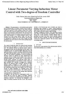
According to (1), by knowing the speed and the b.e.m.f. of a coil, it is possible to obtain the required force acting on the current taking into account the position of the glider. Fig. 4 shows the voltage measured on four contiguous coils by imposing a constant speed to the glider. With the chosen distance between coils, and two PM on the glider, the electromagnetic force is produced by supplying two suitable coils at the same time. The independent control of the current of each coil allows to impose a desired shape to the current reference of the coil. As a consequence, the force profile applied to the glider can be optimised. To illustrate the flexibility of the system, two different strategies are presented here: the simple “constant” current profile and the “quasi constant force” current profile. D. “Constant” current profile This strategy is straigthforward, the current has a constant, positive or negative value according to the sign of the b.e.m.f (fig. 5). As it can be seen, the force profile produced by two adjacent coils has an important ripple superposed to the average value. E. “Quasi constant force” current profile The original idea was to impose a profile of the current equal to the reciprocal profile of the b.e.m.f. In this way, according to (1) and the induced voltage described in Fig. 4
Fig. 8. Whole assembled system
the obtained force profile is theoretically constant. However, in the zone where the voltage is near to zero the required current should be too high, so the current in these ranges should be limited at its maximum allowable value. Actually, to take into account the action of the nearby coils, the current has been shaped with lower values, as it can be seen on Fig. 6a. As already stated, two coils must be energized at each glider position, and we can always identify a “first” (i.e. the closer) and a “second” (i.e. the farther) coil. The current profile in the second coil is symmetrical with respect to the current symmetric axis. Only the current profiles in the “exploited zone” (Fig. 6a) are used. With this strategy, the behaviour of the force is the envelope of the forces that would be generated by each couple of coils, as shown in fig. 6b. IV.
POWER ELECTRONICS AND CONTROL SYSTEM
The whole assembled system is shown in fig. 8. The master board and the four slave boards, together with the corresponding four power boards, are shown. The 24 coils linear motor prototype with two gliders is shown too. A. General structure of the control The control of the system has been entirely designed with DSP processors. The architecture of the system is of MasterSlave type, as shown in Fig. 7. The control structure is made of two nested regulation loops, the external position loop supplying the reference to the internal coil current loops. The master processor manages the position loop. The sampling frequency of the position loop is 8 kHz. Each slave processor manages the current loops of six coils, with a switching frequency of 24 kHz. The current of each individual coil is then separately controlled. The master deal with the measures of the gliders positions, calculates the required forces and sends both information (force and position for each glider) to all the slave processors through an SPI (Serial Peripheral Interface) bus. The communication is unidirectional; the slave processors do not send information back to the master. From the glider position received by the master, each slave is able to evaluate if one or more of its controlled coils must be energized, and from the force reference it can evaluate the
(a)
(b) Fig. 9. Electronics boards: a) Control board, master b) Power board, six coils
current level to be imposed on the coil, according to the offline calculated profile. The master-slave configuration of the control allowed to successfully solve the problem of the passage of the glider from a coil controlled by one slave DSP to a coil controlled by the next slave DSP. B. Control boards (DSP) The control board layout is shown in Fig. 9a. The control boards are based on the Texas Instruments DSP controller TMS320F2812. The complete system is made of five control boards, one for the master processor and four for the slave processors. The master and the slave boards are identical. The connectors for the optic encoder have been mounted on the master card only. Each slave control board is connected to a power board. In order to guarantee a good immunity a galvanic isolation has been chosen for the SPI bus, making use of the Analog Devices ADuM 1400 four-channel digital isolator. C. Power boards The power board layout is shown in fig. 9b. On each board there are six inverters. The converter topology is a half bridge with capacitor middle point. The switching components are MOSFETs (Fairchild Semiconductor FQD12N20, 200 V, 9 A). Each coil is then supplied by a single inverter branch, connected to a symmetric ±25VDC bus. This choice of the power structure has been made in order to minimize the number of power semiconductors to be used on the whole system. The maximum DC voltage is ±
60 V with a current of 2 A. The current measurements are made with shunt resistors and Avago Technologies HCPL 7510 optocouplers. D. Modeling of the system Fig. 10 shows the block diagrams of the two control loops. The current loop (Fig. 10a) includes the PI controller Gci(s), the transfer function of the power converter Gcm(s), the transfer function of the motor coil Gmot(s) and the average force constant KFav. The effects of the b.e.m.f are modeled by the average voltage constant KEav. The position loop (Fig. 8b) includes the position PID controller Gcx(s), the closed loop current transfer function Gi(s), the transfer function of the mechanical part Gmec(s) and an integrator that allows the calculation of the position from the speed. The modeling of the mechanics takes into account the mass of the cart and of the additional mechanical load and the friction (CF). E. Control parameters calculation The chosen current controller is a PI. The integral term has been calculated by compensating the dominant pole of the system, while the proportional term is calculated by imposing as usual a phase margin of 60°. Fig. 11 shows the Bode diagrams of the open loop transfer function of the current. With reference to the form ⎛ s ⋅ Tii + 1 ⎞ ⎟ Gci ( s ) = K p ⋅ ⎜⎜ ⎟ i ⎝ s ⋅ Tii ⎠
we obtained:
Fig. 10. System block diagram: (a) current loop, (b) position loop, (c) mechanics model.
(2)
Fig. 11. Bode plots of the current loop
Ld = 1.22 ms Rs K pi = 5.6
Tii =
Fig. 12 Bode plots of the position loop
(3)
(4) The position controller is a PID. The derivative component compensates for the integral behavior of the system. The controller parameters have been calculated according to the symmetrical criterion [11]. The value of the constants Tix and Tdx shown by eq. 6 is equal to the mechanical time constant of the system. The proportional term is calculated again in the frequency domain, imposing a phase margin of 60°. Fig. 12 shows the Bode diagram of the position open loop transfer function. With reference to the form Gcx ( s ) = K px ⋅
1 + s ⋅ (Tix + Tdx ) + s 2 ⋅ Tix ⋅ Tdx s ⋅ Tix
(5)
m 1.54 = ≅ 77ms CF 20
(6)
we obtained Tix = Tdx = Tmec =
K pi = 25
(7)
F. Simulation Simulations have been performed using Matlab. The model of the motor used for the simulation is the theoretical one, but the actual system saturations due to the maximum voltage and current available have been taken into account. The voltage limitation is ± 25 V and the current limitation is
Fig. 13. Position step of 0.5 m
± 2.5 A. A simulated position step is shown in fig. 13 (together with measurements, see section V). V. TEST RESULTS A. Current loop test The current loop has been tested with a nominal current step response. The simulated and the measured results are shown in Fig. 14, which shows the good agreement between the two. The current loop dynamics allow to impose the current profiles discussed in section I. B. Position loop test, one glider Transition from a coil controlled by one slave DSP to a coil controlled by the next slave DSP can be easily and smoothly achieved. The position regulation has been exaustively tested. Fig. 13 shows the simulated and the measured results with a 0.5 m step. The same behaviour is shown by the two curves. The regulation time is about 400 ms. The position overshoot is lower than 3%. The maximum speed of the system is around 1.4 m/s. C. Position loop test, two gliders The system has been tested with two gliders. In this case four coils, two for each glider, are active at the same time. The test results were successful. VI.
CONCLUSIONS
In this paper an active way linear synchronous motor with multiphase independent supply has been presented. The whole system, motor, power elecronics and control has been built and succesfully tested. In particular, the power and control structure, based on a multi-DSP master-slave approach, has been tested and validated. Main advantages in comparison to the sector concept are the possibilty to impose a suitable current profile on each coil and a simpler management of several glider. Next step will be the investigation on sensorless techniques. The proposed control structure could be also used on other kind of multiphase applications, such as high power multiphase rotating motors for marine applications, of course by completely redesigning and adequating the power section.
(a)
(b) Fig. 14. Current step, (a) simulated, (b) measured
VII.
ACKNOWLEDGMENT
The authors gratefully acknowledge Prof. A. Rotzetta (EIA, Fribourg, Switzerland) for his contribution to the electronics boards, along with Dr. Nicholas Wavre and ETEL SA for the support to the whole project. VIII.
REFERENCES
[1] I. Boldea, S.A. Nasar: “Linear electric actuators and generators,” Cambridge University Press, 1997. [2] J. F. Gieras and Z. J. Piech: “Linear Synchronous Motors, Transportation and Automation Systems,” Boca Raton, FL, CRC Press, 2000. [3] P.-K.Budig: “The application of linear motors,” Power Electronics and Motion Control Conference, 2000. Proceedings. IPEMC 2000. The Third International, Volume 3, 15-18 Aug. 2000 Page(s):1336 - 1341 vol.3 [4] F. Lotti, M. Salmon, G. Vassura, A. Zucchelli: “Selection of linear motors for high-speed packaging machines,” in Proc. IEEE/ASME Int. Conf. Advanced Intelligent Mechatronics, vol. 1, Como, Italy, Jul. 8–12, 2001, pp. 659–664. [5] S. Chevailler, M. Jufer, Y. Perriard, T. Duenser, H. Kocher: “Linear motors for multi mobile systems”, IEEE IAS Industry Applications Conference, 2005, Volume 3, 2-6 Oct. 2005, pp. 2099 – 2106. [6] Y. Kim, M. Watada, H. Dohmeki: “Reduction of the cogging force at the outlet edge of a stationary discontinuous primary linear synchronous motor,” IEEE Trans. Magn., vol. 43, no. 1, pp. 40–45, Jan. 2007. [7] K. Yoshida, H. Takami, and A. Fujii: “Smooth section crossing of controlled-repulsive PM LSM vehicle by DTC method based on new concept of fictitious section,” IEEE Trans. Ind. Electron., vol. 51, no. 4, pp. 821–826, Aug. 2004. [8] M. Leidhold, M. Mutschle: “Speed Sensorless Control of Long-Stator Linear Synchronous-Motor arranged by Multiple Sections,” IEEE transaction on Industrial Electronics, vol. 54, no. 6, December 2007, pp. 3246 3255. [9] R. Benavides, P. Mutschler: “Controlling a system of linear drives,” in Proc. IEEE-PESC, 2005, pp. 1587– 1593.
[10] A. Cassat, B. Kawkabani, Y. Perriard, J.-J. Simond : “Modeling of long stator linear motors - application to the power supply of multi mobile system,” ICEM, 18th International Conference on Electrical Machines, 2008, 6-9 Sept. 2008 ,Vilamoura (P). [11] H. Bühler: “Conception de systèmes automatiques,” Presses polytechniques romandes, 1988. IX.
BIOGRAPHIES
Tazio Beltrami was born in Stabio, Switzerland, in 1986. He received the M.S. degree in electrical engineering from the University of Applied Sciences of Western Switzerland, Yverdon-les-Bains, Switzerland, in 2008. After graduation, he worked as a Researcher in the Institut of Electrical Energy, University of Applied Sciences of Western Switzerland, Yverdonles-Bains, Switzerland, in the power electronics field. His research interests include power electronics for space applications and power quality. Mauro Carpita (M’99) was born in Genova, Italy, in 1959. He received the M.S. degree in electrical engineering in 1985 and the Ph.D. degree in electrical engineering in power electronics in 1989, both from the University of Genova, Genova, Italy. Following graduation, he began his research activity in the corporate research unit of Ansaldo (Genova, Italy) in the field of power electronics for drives and power quality. From 1997 to 1999, he joined Lincoln Electric (Savona, Italy) as a technical office manager, working in the field of power electronics welding machines. From 1999 to 2003, he has been with ABB Ricerca (Milano) and later with ABB Servomotors (Asti, Italy) as senior scientist and power electronics labs manager in the field of servo and very high speed drives. From 1998 to 2001 he has been in charge of the course “Power electronics devices for utility applications” at the University of Cassino, Italy. From 2003 he is Professor of Power Electronics at the University of Applied Sciences of Yverdon-les-Bains, Switzerland. His research interests include power electronics, rotating machinery, and automatic control, particularly in high-power converters and electric propulsion. He is the author or co-author of more than 50 papers in these fields. He is the holder of four industrial patents. Dr. Carpita is an IEEE Member and an EPE Member. Serge Gavin was born in Lausanne, Switzerland, in 1983. He received the M.S. degree in electrical engineering from the University of Applied Sciences of Western Switzerland, Yverdon-les-Bains, Switzerland, in 2005. After graduation, he worked as a Researcher in the Institut of Electrical Energy, University of Applied Sciences of Western Switzerland, Yverdonles-Bains, Switzerland, in the power electronics field. His research interests include power electronics converter for high voltage applications, multilevel converters and DSP applications. David Moser was born in Nyon, Switzerland, in 1980. He received the M.S. degree in electrical engineering from the University of Applied Sciences of Western Switzerland, Yverdon-les-Bains, Switzerland, in 2006. After graduation, he worked as a Researcher in the Institut of Electrical Energy, University of Applied Sciences of Western Switzerland, Yverdonles-Bains, Switzerland, in the power electronics field. His research interests include power electronics converter and DSP applications.