Linear DC Motor. M. Norhisam, H. Ezril, M. Senan, N. Mariun, H. Wakiwaka, M. Nirei. Abstract: Linear motor has gain popularity as linear motion drive in office ...
First International Power and Energy Coference PECon 2006 November 28-29, 2006, Putrajaya, Malaysia
476
Positioning System for Sensor less Linear DC Motor M. Norhisam, H. Ezril, M. Senan, N. Mariun, H. Wakiwaka, M. Nirei Abstract: Linear motor has gain popularity as linear motion drive in office and factory automation which provides an alternative method to conventional rotary motor. Chip mounting is one of linear motor applications especially for Linear DC Motor (LDM). Displacement sensor which is normally used for positioning on the system, made the system expensive. This paper discusses the application of sensor less on positioning system for LDM. A spring is used to determine the position, while the spring displacement which is proportional to the thrust was produced by the motor. The thrust itself can be controlled by controlling the current supplied to the motor. Therefore, the positioning of LDM can be controlled by varying the current value. The approach used in this paper is to control the current is by manipulating various pattern of Pulse Width Modulation (PWM) signal. As a result, the settling time less than 32ms for 10mm positioning has been achieved.
linear motor has been gradually replaced old style conveyer system at assembly lines. Motion control of a motor application are used to control the movement of an object (motor shaft) accurately based on speed, distance, load, inertia or a combination of all these factors. The control algorithms normally executed by a digital controller such as microcontroller or DSP. Additional circuit normally required for signal conditioning and to isolates the digital component from high voltage circuit. For a typical DC motor, techniques used to control speed and positioning are controlling the voltage and current supplied to the motor. This research manipulate Pulse Width Modulation (PWM) signal to control the current supplied to the motor, thus speed and the displacement (position) of linear DC motor can be controlled.
Keywords: Linear DC Motor, spring, current value, Motor Driver, PWM signal!
A. Basic structure ofLinear DC Motor Basic structure of linear dc motor [1] is shown in Fig. 1. It consists of a stator yoke, a moving coil and a couple of permanent magnets with similar pole facing each other. The moving coil is able to move either in forward or reverse direction depends on the polarity of the power supply.
I. INTRODUCTION Linear motor provides direct linear motion without mechanical transmission devices. Unlike conventional rotary motor, the absence of intermediate mechanical transmission devices such as gear, belt, chain and motor coupling eliminates backlash and compliance, reducing friction and increasing motor efficiency. Simple structure of linear motor offer high flexibility to the machine in terms of size and space. Few components in the motor and little lubrication made installation and maintenance becomes easy. There are many application of linear motor and it is various from simple sliding door to a fully controlled CNC machine. The size of the motor are also varies from a small robot end-gripper to the full size of bullet train in Japan. Recent development in manufacturing industry shows that M. Norhisam is with the Department of Electrical and Electronic Engineering Department, Universiti Putra Malaysia, 43400 UPM
Serdang, (e-mail:;
a
H. Ezril is with Faculty of Engineering, International university college of technology, Twintech, Bandar Sri Damansara, KL (email: ezril dXyahoo.com) N. Mariun is with the Department of Electrical and Electronic Engineering Department, Universiti Putra Malaysia, 43400 UPM
Serdang, (e-mail: normannengupm.edum
1-4244-0273-5/06/$20.00 (C)2006 IEEE
II.
BASIC PRINSIPLE OF LINEAR DC MOTOR
Stator y oke
rm anent Magnet
oving
coil
Air gap
Fig. 1 Basic structure of LDM
The basic principle of thrust in linear dc motor is derived from basic iBI laws or known as Ampere's law. Thrust in the moving coil can be expressed as equation (1): Fm =NcIcBglc
(1)
477
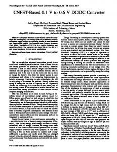
Where, Fm is thrust in (N), N, is number of coil turns in turn, I, is current supplied to the coil in (A), Bg is flux density in the gap in (T) and 4, is length of the coil in gap in (m). The thrust constant of the LDM is depending on the value of Nc, Bg and 4c, and these parameters are fixed when the motor has been designed. Therefore, the force produced by the motor can be controlled by controlling the amount of current supplied to the coil. Assuming
Kf = NcBglc Fm
=
KfIC
0.0 0.0
I
0.5
PWM
(3)
3.5 -
Set Position
(2)
Thus, it implies that the force produced by the motor is proportional to the current supplied. High values of forces will be produced if high values of current are supplied to the coil. Fig. 2 shows the motor thrust characteristic. The thrust constant for LDM is 1.6 N/A.
3.0
MOSFET transistors. The speed of switching is depends on the PWN frequency and the amount of current flowing to the coil depends on PWM duty cycle. The H-Bridge circuit also used to isolate the other electronic components from electrical problem.
1.0 1.5 2.0 2.5 Coil current I (A)
IVoltage I Current
Fig 3 Open loop sensor less motor driver for LDM B. Pulse Width Modulation (PWM)
The controller unit is use to provides PWM signal to H-Bridge unit. PWM is a digital signal used to control analog circuits by repeating series of on and offpulses. The on-time is the time when the DC supply is applied to the load (H-Bridge circuit), and the off-time is the period of time when the supply is switch off. There are 2 important variables for generating PWM signal [6], the frequency and the duty cycle. For PWM, frequency determines how fast the switching turn on and off, while the duty cycle (%D) is the ratio of on as a percentage of total switching time. Fig. 4 shows the PWM signal of different Duty cycle with similar frequency.
3.0
Fig 2 LDM thrust characteristic.
D =10% tD
vh
A. Sensor less Motor Driver
Fig 3 shows the block diagram of open loop sensor less motor driver for LDM. Motor driver is used to control the motion and position of the motor. This electronic circuit consists of a microcontroller and H-Bridge unit. The microcontroller used in this research was designed based on Atmel AVR ATMega8535. The purposes of microcontroller are to perform computational process and provide a proper control signal to the H-Bridge unit. Generally, the H-Bridge circuit is used to control the speed and direction of the motor. The circuit consists of four MOSFET transistors IR640 and two MOSFET drivers IR21 10. PWM signal generated by the microcontroller unit is send to MOSFET driver which will turn on and off the
D =50 % .t
III. LDM SENSORLESS POSITIONING SYSTEM V
D
=800
Fig. 4 PWM signal with different duty cycle IV. CHARACTERISTICS OF SENSORLESS POSITIONING SYSTEM A. Experiment setup for LDMpositioning system In this research, the idea of controlling the speed and the position of linear dc motor is by manipulating various pattern of PWM signal. A little modification is made to the motor by connecting a spring to the motor as shown in Fig. 5. A displacement sensor is also used in the experiment to
478
measure the displacement of the motor. Power supply to the LDM driver has been set at 12V with 2A. Digital oscilloscope 4 Ch (Tektronix TDS2010)
for different duty cycle ranging from 10% to 100% while fig 7 shows the time response of motor displacement for each duty cycle. 25
o o a o]
n
Currentprobe (TCT 06 Al)
20 -
Fig. 5 Experiment setup for LDM positioning system The spring connected to the motor's coil is used to exert the forces produced by the motor. According to Hooke's Law [3], the force of a spring exerts is proportional to the distance it has been displaced from rest.
Fc = -kx
m
d2x dx +c +kx = Fm dt dt
1010 0
-
I
0
20 40 60 80 PWM duty cycle D (%)
100
Fig 6 Motor displacement for different value of PWM duty cycle. The frequency is set at 9 kHz. Motor power supply is set at 12V, 2 Ampere.
(4)
Where Fc is force exerted by spring, k is spring constant, x is distance the spring displaced from rest. Spring constant, k used in the experiment is 88 N/m. A general equation of motion is similar to the damped force oscillation of a mass-spring system [4] [2] and can be described as:
15
25 ,-
20
x 15
E 10 0
(5)
Where Fim is external force (Motor force), m is the mass, c is the damping coefficient (friction) and k is spring constant. Once the external force (motor force) acts on the body (motor's coil), it will produce a motion and displace the body to some distance until it reach the equilibrium point. By increasing the external force fm, displacement x, of the body (motor's coil) is also increased. From (2), the external force (motor force) is proportional to the current supplied to the coil. Therefore, by increasing the current value, the displacement of the motor will also increased. B. Characteristics of sensor less positioning System This section discusses the results obtain from the experiment done as in previous section. The objective of the experiment is to make the motor displace 10mm from initial position. The frequency of PWM signal has been set at 9 kHz. The value of duty cycle then will be used to control the displacement of motor. Power supply for the motor has been set at 12V with 2A current. Fig 6 shows motor displacement
0
0
50
100
150
200
Time t (ms) Fig. 7 Time response of motor displacement for different duty cycle (D 0 o)
Single stage PWM The easiest way to control the position of the motor is by using a single pattern of PWM signal. This approach uses only one value of PWM's duty cycle to energize the coil. Based on motor response in Fig. 6, 14% of the duty cycle had displaced the motor 10mm from initial position. Therefore, for single stage approach, 14% duty cycle has been used to displace the motor 10mm from rest position. Time response for 14% duty cycle is shown in figure 8. Rise time is about 80ms. There are no overshoot and no steady state error.
479
20
D= 25%!
20
/
15
2
-4. '.. ..__7...........w... ._
15
!
1i0
:
2= D
1i0%! D= D514%
a 10
0.
.a
5 11
n
0
50
150 Time I (ms ) 100
200
250
Figure 8: Single stage time response for 5%, 10%, 14%, 20% and 25% duty cycle. Dual stage PWM
Fig. 9 shows dual stage PWM signal. Dual stage approach implemented to improve the rise time of single stage approach. For dual stage approach, two values of duty cycle are used to drive the motor. The first duty cycle is used to reduce the rise time while the second duty cycle is used to maintain the position of the motor at desired position.
was
Based on the time response of different duty cycle ranging from 10% to 100% as shown in Fig 6, 50% duty cycle and above produces almost the same speed and reach 10mm within 32ms. Therefore for dual stage approach, 50% duty cycle was used as first duty cycle for the first 32ms (tl), followed by 14% duty cycle to maintain displacement of m from initial position. Fig. 9 shows the result for dual stage approach. Overshoot appears in the response due to the inertia of the moving coil. By decreasing the period of the first duty cycle, the overshoot is also decreased; decreasing the period of first duty cycle had increased the rise time of the response. AAL
tki
L0
-10 0
100 Time t
20 0
Fig. 10 Dual stage response for different t1 Triple stage PWM
Triple stage approach was used to eliminate the overshoot produced by dual stage approach while maintaining fast rise time. In triple stage approach, three different values of duty cycle were used to energize the coil. The PWM pattern for triple stage approach is shown in Fig. 11. The first duty cycle is used to increase the speed of the motor, thus reduce the rise time as in the dual stage approach. The second duty cycle is used to reduce the inertia effect by sending reverse signal to the coil. The third duty cycle is used to maintain the motor at desired position. Fig. 12 shows the result of triple stage approach. The period for the first duty cycle (50%) has been set at 32ms as in dual stage. The same duty cycle and period are also applied to reverse the signal. The motor displace 10mm and reverse to the initial position before moving forward and maintained at 10mm displacement as shown in Fig. 12. By decreasing the period of the reversed signal (t2), the settling time is also reduced. The best response for triple stage approach was achieved by using 50% duty cycle for 32ms, followed by the reversed 50% duty cycle for 4ms and maintained at 14% duty cycle.
t2~ ~ ~ ~ ~ ~-
u
bJo ct
-4-
---4
0
D= 50%
D= 14%
P-.
t= Oms
Fig. 9 Dual stage PWM signal
300
s)
t Fig.
11
Triple stage PWM signal
480 20
20 15
-,
15
t0 10-
t 10 ct
.t
5
5
0-
0
-100
0
100
200
-100
300
100 200 Time t (ms)
0
Time t (ms)
Fig. 14 Quartet stage response
Fig. 12 Triple stage response Quartet stage PWM In triple stage approach, the reversed signal help to eliminate overshoot, but the motor moves slightly reverse before it maintain at the desired position. In order to remove the reverse movement, quartet stage uses four different duty cycle. The first and second duty cycle follow as triple stage approach. The third duty cycle is added to remove the reverse movement by sending forward signal with the same magnitude as reverse signal. The forth signal is 14% duty cycle to maintain the motor at desired position. Fig. 14 shows the result of quartet stage approach. The best response for quartet stage approach was achieved when using 50% duty cycle for 32ms, followed by reversed 50% duty cycle for 8ms, followed by forward 50% duty cycle for 8ms and finally maintained at 14% duty cycle. The rise time is approximately 32ms with no overshoot and no steady state error.
300
C. Comparison of control approaches Fig 15 shows the best response for every approach used in the experiments. The performance of each response is concluded as in Table 1. For single stage response, the rise time is 80ms. Dual stage approach however provides better rise time compared to single stage approach. The rise time for dual stage approach is 60ms. For triple stage approach, the rise time is 34ms, which is much better than the previous two approaches. However, overshoot of 10% appear in the triple stage response.
Based on responses shown in Fig. 15, quartet stage produce the best response among four approaches used in the experiments. The rise time is about 32ms and no overshoot appears in the response. 20
i 15
u
E
10
c.)
.5
Triple stage
Quartet stage
D
stage
Single stage
bJo ct
-4-
---4
0
0
-50 ..P-.
Fig. 13 Quartet stage PWM Signal
0
50
100
150
Time t (ms) Fig. 15 Performance comparison of four approaches used in the experiment Table 1 Comparison of positioning performance. Item Rise time Settling time Overshoot (ms) (ms) (0 o) 80 80 0 Single stage Dual stage 60 60 0 34 60 10 Triple Stage 0 32 32 Quartet Stage
481
V. CONCLUSION This research is a study of a sensor less system for driving and positioning of LDM. This paper emphasized on the programming approach used to control the position of the LDM. A basic LDM has been constructed for the study and experimenting purposes. The electronic controller used to generates PWM signal was designed based on Atmel Atmega8535 AVR. A motor driver circuit has been constructed by using IR21 10 H-bridge driver and IRF640 MOSFET transistor. Multiple sets of PWM signal patterns have been used to drive the LDM and the response have been studied. As a conclusion, multiple values of PWM duty cycle used to drive the motor produces better response compared to single stage duty cycle.
REFERENCES [1] M. Norhisam, A. Noor Azita, J.I Syed,, N. Mariun, "Trust Density Charateristics of Linear DC Motor", Dept Of Electrical and Electronic Engineering, UPM, Malaysia. [2] D.Roy Choudhury, Modern Control Engineering, PrenticeHall, 2005. [3] Madhujit Mukhopadhyay, Vibration,Dynamics and structural systems, A.A Balkema/Rotterdam/Brookfield, 2000 [4] Ervin Kreyszig, Advance Engineering Mathematics, John Wiley & Son, 1999 [5] Wan Abu Bakar Wan Abas, Mekanik Kejuruteraan Dinamik, Dewan Bahasa Pustaka, 2001 [6] 4QD-TEC: "Electronics Circuits Reference Archive: PWM speed control". URL: http://www.4qd.co.uk/.