A Linear Induction Motor Control System for. Magnetically Levitated Carrier System. Abstract-A new electromagnetic suspension system has been devel- oped ...
102
IEEE TRANSACTIONS ON VEHICULAR TECHNOLOGY, VOL. 38, NO. 2, MAY 1989
A Linear Induction Motor Control System for Magnetically Levitated Carrier System
Abstract-A new electromagnetic suspension system has been developed, which cuts off electric power-collecting devices from a magnetically levitated vehicle. This system makes it possible to transport materials with no mechanical contact at all between the vehicle and ground facilities. A control system for linear induction motors used in the magnetically levitated carrier system is described. The system was developed to transport materials in an environment which must be kept free from even microscopic dust motes and trivial noise. It is one of the applications which make the most of the newly developed electromagnetic levitation system. The linear induction motor control method for positioning a vehicle at the station, and several kinds of switches without any mechanical motion in the ground facilities, are introduced. Furthermore, a supervisory control system for the magnetically levitated carrier system is also introduced.
INTRODUCTION
M
ANY ELECTROMAGNETIC levitation technologies have already been developed and reported [ 11-[6]. However, strictly speaking, almost all the vehicles in these systems are not completely levitated. That is, there are mechanical contacts between the vehicle and ground facilities to supply electric power to the vehicle. This power-collecting device generates a mechanical drag force, which is relatively large in the low vehicle velocity region. Besides, it prevents the system from being maintenance free, which should be one of the distinctive features of a magnetic levitation system. The authors have developed a new magnetic suspension system, which cuts off electric power-collecting devices from conventional electromagnetic suspension systems [7]. This newly developed technology is foreseen as being the material transportation system in such an environment which must be kept free from even microscopic dust motes or trifling noise, for example, in a super clean room in semiconductor manufacturing plants or biochemical plants, hospitals and offices. This paper describes a control system for linear induction motors used in the magnetically levitated carrier system, which is suitable for such applications. In such circumstances, both vehicles and guideways should be compact and light in weight. Therefore, the copper reaction plate is mounted on the vehicle, and the primary core units Manuscript received February 1987; revised April 4, 1989. T. Azukizawa and M. Morishita are with the Toshiba R&D Center, Toshiba Corporation, 4-1, Ukishima-cho, Kawasaki-ku, Kawasaki-city, Kanagawa, 210 Japan. S. Kanda, N. Tamura, and T. Yokoyama are with Fuchu Works, Toshiba Corporation, 1, Toshiba-cho, Fuchu-City, Tokyo 183, Japan. IEEE Log Number 8929442,
with three phase windings are installed at appropriate intervals along the guideway. Thus, linear induction motors applied in this system are classified as short stator, short rotor units. Besides, in this system, the air gap distance between surfaces of the primary core and reaction plate changes according to the weight of the load shipped on the vehicle. Considering these factors, a positioning control method using a microprocessor with position sensors is adopted in the magnetically levitated carrier system. In this system, vehicles are also switched without any mechanical contact, as well as being positioned completely contact free. A NEWELECTROMAGNETIC LEVITATION SYSTEM A newly developed magnetic levitation system has cut off power-collecting devices by using hybrid magnets which are composed of a permanent magnet and control electromagnets. In this system, the control electromagnets were controlled to maintain an air gap length so that the attractive force between the permanent magnet and ferromagnetic guide rails always balanced the total weight of the vehicle and its load shipped on it. That is, the reference value of the air gap distance in the gap control loop was changed according to the weight of the load shipped on the vehicle. Thus, the electric power required to excite the electromagnets to keep the vehicle levitating was significantly minimized. It became possible for onboard secondary batteries to supply energy required to levitate the vehicle for a sufficiently long time for the commercial-based transportation system. Fig. 1 shows a cross-sectional view of the vehicle and guideway for the magnetically levitated carrier system. The guideway, which was suspended from a ceiling or crossbeam of the building, was composed of ferromagnetic guide rails facing the hybrid magnets mounted on the vehicle, auxiliary guide rails for unexpected troubles. Furthermore, linear induction motor primary cores facing the reaction plate attached to the top of the vehicle, inverters and controllers with optical sensors detecting the vehicle position and its cruising velocity were also installed in the guideway. The vehicle was equipped with four hybrid magnets, gap sensors, auxiliary wheels to support the vehicle in case of unexpected troubles and hooks for hanging the loads to be carried. The vehicle was also equipped with control circuits for calculating reference value for electromagnetic coil currents, power amplifiers for exciting the electromagnets, batteries for use as
0018-9545/89/0500-0102$01.00 O 1989 IEEE
103
AZUKIZAWA et al.: LINEAR INDUCTION MOTOR CONTROL SYSTEM
TABLE I
Guideway I
I
w’
SPECIFICATIONS FOR SINGLE-SIDED LINEAR INDUCTION MOTORS IN MAGNETICALLY LEVITATED CARRIER SYSTEM
Purposes Voltage(V) Current ( A ) Frequency( Hz 1 Pole No. Core Size Length (mm) Width (mm) Height (mm) Synchronous
490
295
80
80 50
1 I5 100 50
400 I 00
100
50
Reaction Plate Material Thickness (mm)
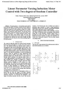
Fig. 1.
Magnetically levitated carrier system: cross-section view.
the power supply, copper reaction plates for linear induction motor. Single-sided linear induction motors were selected to make it possible to switch vehicles without any mechanical movement in the ground facilities. Primary cores were installed in the center of the guideway so that the height of its surface coincided with the height of the lower surface of the ferromagnetic guide rails. This was the mechanism that allowed the vehicle to be switched in any direction by arranging the guide rails to be fed into the desired branch direction. A larger thrust force would be obtained by putting an iron plate on the reverse side of the copper reaction plate. However, it would generate excessive attractive force between a vehicle and primary cores, which would act as a disturbance for the gap control loop when the vehicle passed under the excited primary cores. Therefore, a copper plate without an iron layer on its back was adopted as the reaction plate in this system. It greatly contributed to reduce vehicle weight. LINEAR INDUCTION MOTORS At vehicle velocities under 5 m/s, which is sufficient for a transportation system operating in an environment such as mentioned previously, the aerodynamic drag force and magnetic drag force due to eddy currents in the ferromagnetic guide rails are very small. Therefore, it is not necessary to install a primary core with three phase windings over the whole length of the guideway. It is enough to install short primary core units at an appropriate intervals along the guideway. That is, vehicles are accelerated or decelerated only when they pass the excited primary cores, and they cruise by their inertia between the primary cores. By adopting this construction method, the guideway cost becomes significantly cheaper, and the guideway weight becomes light. Furthermore, to excite primary cores in turns according to the vehicle movement, the power fed to the linear induction motor primary core units becomes small. There were four models of linear induction motors in this system. The first model was for positioning at the station and accelerating or decelerating during the long, straight portion of
Air Gap (mm)
4
4
4
Thrust ( k g )
69
49
02
Mass
(kg)
22
14
70 30 50
5
4
08
the guideway. The second model was for accelerating along the curved guideway. This model had a shorter core than the first one, so that it could be installed in the space between the inner and outer curved guide rails. The third one was for a curved or lateral switch. And the last one was for a rotating switch without any mechanical contact. Specifications for these linear induction motors are indicated in Table I. As these linear induction motor primary cores were very short, vehicles passed these primary cores in a very short time. Therefore, the operation rate for these primary cores was extremely low. Thus, the current densities in the coils in these linear induction motors were selected as 8-10 A per square millimeter. The maximum vehicle velocity of 5-6 m/s is sufficient for use in a transportation system operating in such environment as mentioned previously. Thus, the synchronous velocity for TLM-24 linear induction motors for high speed operation is selected as 5.8 m/s, when excited by 60 Hz. A variable frequency inverter drive system enables a higher maximum vehicle velocity if necessary. CONTACT-FREE POSITIONING CONTROL SYSTEM Though the thrust force characteristics for a short rotor or short stator, single-sided linear induction motor have been estimated analytically [8]-[ lo], these results were obtained under the restriction that either the rotor or the stator was extremely longer than the other. In a magnetically levitated carrier system, the reaction plate length was comparable to the primary core length, as shown in Table I. The air gap length between the reaction plate attached to the vehicle and the surface of the primary cores, changes according to the weight of the load shipped on the vehicle. Therefore, it is very difficult to control the thrust forces of single-sided linear induction motors based on analytical results in this system. Thus, a microprocessor-controlled inverter with position and
104
IEEE TRANSACTIONS ON VEHICULAR TECHNOLOGY, VOL. 38, NO. 2, MAY 1989
Microprocessor
Linear
- Induction
Inverter
- Inter-
- Vehicle
Motor
face
I I
U
I
Position
I I
Velocity Detector
1
vs =vl
I
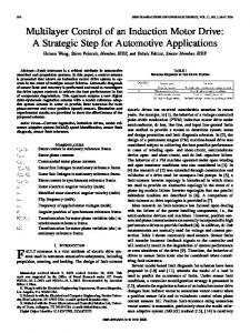
Fig. 2. Control system for linear indwtion motor.
vs L-IOV I
PD1
D
PD2
I- Ipl --I--lp Stripes
Fig. 3.
v
PD3 2-l-Ip3-4
I
I
PD4
Vk-Position
VSilOV
Sensor
I Ve hi c Ie
VD 1 VD 2 VD3 Positional relations between LIM primary core and sensors.
velocity detectors was applied to control the single-sided linear induction motors in the system. A fundamental block-diagram for the control system of the linear induction motor used in the system is shown in Fig. 2. A pulse width modulated sinusoidal voltage inverter was mounted on the guideway to excite three phase windings in the primary core unit. The maximum output frequency for this inverter was 80 Hz. The output voltage to the output frequency ratio was constant in the 3-60 Hz range, while the output voltage was constant over 60 Hz. The output frequency of this inverter was controlled by a microprocessor through a D/A (digital to analog) converter in the interface circuit board. The position sensor set consisted of a light-emitting diode (LED) and a phototransistor. It detected the cover plate of the vehicle. Four position sensors were mounted on the guideway near the primary core, spaced [PI,Ipz, and [P3,respectively, as shown in Fig. 3. Position sensors PD2 and PD3 should be placed in symmetrical positions with regard to the center of the positioned vehicle. Although the space between the two inner position sensors PD2 and PD3 must be just narrower than the length of the detecting plate I C on the vehicle, other spacings, lp1 and lp3,are not restricted, when they are shorter than a half of the detecting plate length IC. The velocity detector was composed of an optical sensor which is an LED and a phototransister set, a sensor head guided by optical fibers, and an F/V (frequency to voltage) converter. Three velocity sensors were mounted on the guideway near the primary core, spaced lvl and lv, with respect to each other, as shown in Fig. 3. The central velocity sensor should be placed near the center of the vehicle stopped at a predetermined position, but it need not be placed very exactly. Spacings lvl and Iv2 should be set a little shorter than the vehicle length I C . These velocity detectors count number of 3-mm wide stripes painted on the cover. The output signal from the F/V converter was introduced to the A/D converters
INVERTER OFF
'USITION,
I
,
c
v
s
I (V12V2)
~
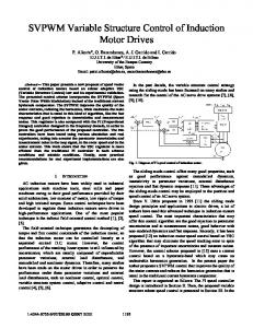
NEXT STEP Fig. 4. Simplified flowchart for linear induction motor positioning control in magnetically levitated carrier system.
in the interface circuit board. A microprocessor was able to detect vehicle velocities faster than 5 m / s . These components for a local linear induction motor controller, shown in Fig. 2, were assembled into a unit, which was mounted in the guideway next to the primary core to be controlled. This construction reduced electric noise which might be induced on longer signal cables, and contributed to make the guideway simpler. A simplified flowchart showing the positioning control for linear induction motors in the magnetically levitated carrier system is shown in Fig. 4. This control flow is applied to the microprocessor when its subsidiary primary core encounters the vehicle to be stopped. First, the microprocessor reads the position detector signals through the interface circuit, and selects which velocity sensor should be used according to the vehicle position. That is, velocity sensor VDI is selected while position sensor PD1 is detecting the vehicle, velocity sensor VD2 is selected while position sensors PD2 and PD3 are detecting the vehicle singly or simultaneously, and VD3is selected while PD4 is detecting the vehicle. The vehicle velocity, which is read from the selected velocity detector, is compared with the preset velocity VO,which is the lowest vehicle velocity to be detected with
105
AZUKIZAWA et al.: LINEAR INDUCTION MOTOR CONTROL SYSTEM
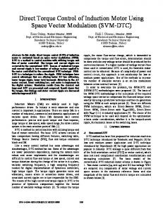
sufficient accuracy, in spite of ripples in the output signals from the F/V converters. When the detected vehicle velocity is faster than Vo, the linear induction motor is driven in the braking operation mode. In this system, the linear induction motor is excited to slip about s = 1.1 during braking operation because the thrust force for a single-sided linear induction motor, with a large air gap and reaction plate without an iron plate on its back, is approximately proportional to slip. When the detected vehicle velocity is less than a preset velocity Vo,the linear induction motor is excited to center the vehicle to the position where position sensors PO2 and PD3 are both detecting the vehicle. The synchronous velocity of the linear induction motor for centering operation is adjusted in two steps. These are: a slower synchronous velocity V2 for precise positioning, while one of the inner two position sensors PO2 and PD3 is detecting the vehicle, and a faster synchronous velocity Vl, while one of the outer position sensors is detecting the vehicle, when the effective length of the reaction plate confronted with the primary core is very short. When inner position sensor PD;?and PD3 are both detecting the vehicle, the inverter is switched off and the position detector is read again after a moment to confirm that the vehicle is stationary. When the vehicle has stopped and both inner position sensors detect the vehicle again, the control moves forward to the next step. Otherwise, the control returns to the start step. As the inverter used in this system had considerable time delay in establishing the required output frequency, the vehicle to be stopped should have decelerated sufficiently by the neighboring primary core unit to the velocity at which vehicles can be stopped within a finite length of a positioning primary core. A primary core unit, with a microcomputer controlled inverter and sensors, can accelerate or decelerate vehicles to any required velocity, as it is possible to detect the vehicle velocity any time the vehicle passes the primary core. Fig. 5 shows an example of output signals from F/V converters for the two velocity detectors VDl and VD2,under positioning control at the station. In this case, the vehicle is decelerated to about 0.2 mls by another primary core unit, located just before the station. Decreasing parts of these two signals represent decelerating vehicle velocity. These data were obtained for the unloaded 8 kg weight vehicle and the 3.2 kg weight loaded vehicle, V, and V2 were 1.34, 0.44 mls, respectively. In both loaded and unloaded cases, the vehicle was well positioned within k O . 5 mm, although the air gap length between the surface of the primary core and the reaction plate changed for these two cases. That is, it became about 4.8 mm for the no load case, and about 3.9 mm for the loaded case. As deceleration during positioning was less than 0.01 G , this system is able to transport a delicate load without any modification.
Fig. 5 .
Velocity detector output signals under positioning control. (a) No load. (b) Loaded.
feature is easily established by arranging ferromagnetic guide rails and primary cores of single-sided linear induction motors in the same horizontal plane. To switch the vehicle in any direction in the horizontal plane, ferromagnetic guide rails were arranged along the loci which four hybrid magnets draw during a switching operation, and small linear induction motor primary cores were installed in a pertinent position to drive the vehicle in both switched and unswitched directions. Fig. 6 introduces three kinds of switches which were adopted in the magnetically levitated carrier system. Their effectiveness has been confirmed as contact free switches by using the test facility. In these figures, only the ferromagnetic guide rails, linear induction motor primary cores, and a carrier with four hybrid magnets are shown for simplification. In the curved switch, as shown in Fig. 6(a), there were three linear induction motor primary cores. The primary core located in the straight guideway A had two operating modes, one was acceleration of the vehicle which was not to be switched, and the other was for adjusting the velocity of the vehicle to be switched, according to velocity detectors which are not shown. A small linear induction motor primary core, located just inside the branch point A 2 ,was excited to generate a traveling magnetic field in the direction as shown in this figure when the vehicle to be switched was passing through. Primary core A 2 was excited slightly in the opposite direction when a vehicle which was not to be switched was passing through. Primary core A 3 ,which was located between curved guide rails, was excited to accelerate vehicles sufficiently to overcome the drag force caused by centrifugal force set up by CONTACT-FREE SWITCH CONTROL SYSTEM the vehicle traversing the curved track. Test results showed The magnetically levitated carrier system as a distinctive that the vehicle which was not to be switched should be feature, that is, the vehicle can be switched with no mechanical accelerated more quickly, compared to a vehicle to be motion at all in both the vehicle and the guide rails. This switched, because the vehicle could pass a straight section
106
IEEEI TRANSACTIONS ON VEHICULAR TECHNOLOGY, VOL. 38, NO. 2, MAY 1989
LIM Primary Core,^
e2
h
B3 8'4 (b)
(C) Fig. 6 . Contact-free switches by single-sided linear induction motors. (a) Curved switch. (b) Lateral switch. (c) Rotational switch.
smoothly as a result of its inertia, in spite of distortion in the shape of guide rails at the switching point. Three small linear induction motor primary cores were used in the lateral switch without any mechanical movement in the ground facility, as shown in Fig. 6(b). The primary core in main line B1 was controlled to slow down the vehicle to be switched. The outer two primary cores in switch portions B2 and B4 were excited to generate a traveling magnetic field in the direction as shown in this figure. Thrust forces by these two primary cores positioned the vehicle to a balanced position, where the hybrid magnets on board stopped at the guide rails of the lateral branches. After position detectors confirmed the vehicle be positioned at the balanced position of the switch, the small central primary core B3 was excited to generate a traveling magnetic field toward the direction of the branch as shown in the figure. Then, the vehicle moves into the branch without any mechanical motion in the ground facilities. When a vehicle which is not to be switched approaches the primary core B 1 ,it is excited to accelerate the vehicle movement, and primary cores B2 and B4are so excited as to accelerate the vehicle, while the central primary core B3
is excited in the opposite direction as shown in the figure. Of course, it is possible to expand branch guide rails toward the opposite side of the branch shown in the figure; that is, a switch like a crossroad is also realized easily. In this case, the central primary core B3 should not be excited when the vehicle is going straight. This lateral switch system was also investigated using the test facility and proved its effectiveness. This lateral switch is foreseen to be used because the space needed in guideways at a switching point is very small, compared with the curved switch shown in the figure. Fig. 6(c) shows a rotational switch system without any mechanical movement in the guideway. There were four small linear induction motor primary cores that were laid out symmetrically to the center of rotation. Two of these primary cores, C2 and C4, were placed parallel to the guide rails in the main line. Another two primary cores, C, and C5, were located parallel to the guide rails in the branch line. A vehicle which was to be switched slowed down by the primary core C1, and was positioned by C2 and C4 to the point in space where four hybrid magnets on board stop at the circled guide rail. After being positioned, the four primary cores were excited to generate a traveling magnetic field in the direction shown in the figure. These four traveling magnetic fields generated a rotating torque in the vehicle. When vehicle movement was detected as having been rotated about 90", the primary core C5was excited in the opposite direction shown in the figure, and primary cores C2 and C4 were switched off. Then, the vehicle moved toward the branch line and was accelerated by primary core C7 in the branch line. Again, the branch guide rails may expand toward the opposite side of the branch shown in the figure. Position sensors, which detect the vehicle positioned and rotated by 90", are placed in the spaces above the guide rails and detect the reaction plate mounted on the vehicle. This completely contact-free rotating switch operating quite efficiently in the test facility. The test facility layout is introduced in Fig. 7. All of the components mentioned above were included. in this test facility. It has been found that all functions needed to drive vehicles without any mechanical contact, which are introduced in this paper, operated quite effective and efficiently. SUPERVISORY CONTROL SYSTEM Fig. 8 shows a blockdiagram of a supervisory control system for a magnetically levitated carrier system. Supervisory control system functions, in the magnetically levitated carrier system, were generally classified into three categories. The controller in the highest ranking category was a host minicomputer, which managed the total flow of materials to be transported. The host minicomputer automatically determined destination for the material to be carried which was set at individual stations, according to the production management system of the entire plant. The master controller in the main line and the block controller in the branch line managed vehicles in their subsidiary lines, according to instructions from the host minicomputer. These middle-ranked controllers tracked every vehicle and determined which vehicle was to carry the material to be transported.
107
AZUKIZAWA et al.: LINEAR INDUCTION MOTOR CONTROL SYSTEM
(
Unlt:mrn 1
Fig. 7 . Test facility layout.
Control for L I M Control
for LIM Control Contro Iler
1
Inverter
__------
-4
Vehicle-
___--_ Station
-------
tj
Fig. 8. Supervisory control system for the magnetically levitated carrier system.
The lowest ranked controllers were the station controllers at the stations, and linear induction motor controllers which were mounted on every primary core. The station controller managed loading and unloading of the materials from the vehicle, and also managed the battery charging system, which charged onboard batteries while the vehicle was loading, unloading, or waiting for the next job at the station. The operating status was always displayed at the master controller. An operator at the station could obtain information about what materials have arrived at that station. He could also instigate a request to transport materials from his station to any other station, using the terminal devices at the station.
CONCLUSION The authors have developed a magnetically levitated carrier system, as shown in Fig. 9, which utilizes the newly developed electromagnetic levitation system. As this new system realized
Fig. 9. Magnetically levitated carrier system.
108
IEEE TRANSACTIONS ON VEHICULAR TECHNOLOGY, VOL. 38, NO. 2, MAY 1989
completely contact-free levitation which has no mechanical contacts (even a power-collecting device), the drive system should control vehicle motion with no mechanical contact. There were specific problems in this system to design drive system using linear motors, that is, air gap between the reaction plate and the primary core surface changes according to the load weight shipped on a vehicle. However, test facility operations have shown that the linear induction motor control system introduced in this paper was effectively and efficiently operated to drive and switched vehicles without any mechanical motions in the ground facilities. This fact indicates that required technologies have been established to transport materials in such environments as locations where even microscopic dust motes or trifling noise cannot be tolerated, such as those represented by a super clean room of less than the ten cleanness class. ACKNOWLEDGMENT The authors thank Mr. H. Koike of Toshiba Fuchu Works, Mr. S. Takamatsu and Dr. K. Asano, both of Toshiba R&D Center, for giving them a chance to present this paper.
Mimpei Morishita was born in Tokyo, Japan, on January 25, 1957. He received the B.S. and M.S. degrees in electrical engineering from Waseda University, Tokyo, in 1980 and 1982, respectively. He then joined Toshiba Corporation, Japan. Since 1980, he has been worhng on the research and development of electromagnetic suspension systems. Currently, he is with the Toshiba R&D Center. Mr. Morishita is a member of the IEE of Japan.
Shuji Kaoda was born in Saitama Prefecture, Japan, on July 5, 1944. He received the B.S. degree in electronic engineering from Nihon Densi Kogakuin College, Japan, in 1968. He joined Toshiba Corporation in 1963, and he has been working on development of electrostatic printing devices, ink jet printing devices and manufacturing automation equipments. Currently, he is a Deputy Manager in Toshiba Fuchu Works.
REFERENCES
[31 141 151
161 171
191 1101
G. Bohn et al., “The electromagnetic suspension system of the magnetic train ‘Transrapid’,” presented at Int. Conf. on MAGLEV Transport ’85, Tokyo, Japan, Sept. 17-19, 1985. M. G. Pollard et al., “Birmingham MAGLEV: Development for the future,’’ presented at Int. Conf. on MAGLEV Transport ’85, Tokyo, Japan, Sept. 17-19, 1985. M. Kitamoto et al., “Evaluation-module/suspensionsystem installed on the HSST-03 vehicle,” presented at Int. Conf. on MAGLEV Transport ’85, Tokyo, Japan, Sept. 17-19, 1985. S. Suzuki et al., “HSST-03 system,” IEEE Trans. Magn., vol. MAG-20, pp. 1675-1677, 1984. B. V. Jayawant, Electromagnetic Levitation and Suspension Techniques. London: Edward Arnold, 1981. V. G. Heiderberg et al., “Die M-Bahn,” ZEV-Glas. Ann. vol. 107, no. 12, Dec. 1983. M. Morishita et al., “A new Maglev system for magnetically levitated carrier system,’’ presented at Int. Conf. on Maglev and Linear Drives, Vancouver, Canada, May 14-16, 1986. S. Nonaka et al., “Design principle of the high speed single-sided linear induction motors for propulsion of magnetically levitated trains,” Electron. Eng. Japan., vol. 101, no. 4, pp. 96-105, JulyAug. 1981. H. Yamazoe, “Analysis and experiments of single sided linear induction motor,” Electron. Eng. Japan, vol. 100, no. 4, pp. 9-18, July-Aug. 1981. A. Mor et al., “Spatial Fourier technique and end effects in the single sided linear induction motor,” Electron. Mach. Electromech., vol. 7, no. I , pp. 47-55, Jan.-Feb., 1982.
Teruo Azukizawa (M’83) was born in Saitama Prefecture, Japan, on February 25, 1946. He received the B.S and M S. degrees in electrical engineering from Waseda University, Tokyo, in 1969 and 1971, respectively. He then joined Toshiba Corporation, Japan Since 1972, he has been working on the research and development of linear motors and magnetic =,uspension systems Currently, he is a Senior Researcher in the Toshiba R&D Center. Mr. Azukizawa is a member of the IEE of Japan.
Noboru Tamura was born in Hokkaido, Japan, on November 15, 1947. He received the B.S. degree in electrical engineering from Hokkaido University, Japan, in 1970. He then joined Toshiba Corporation, Japan. Since 1970, he had been working on designing industrial control equipments, such as paper and film making plant. 1984, he has been working on designing manufacturing automation systems, such as magnetically levitated material transportation system. Currently, he is a Senior Specialist in Toshiba Fuchu Works. Mr. Tamura is a member of the IEE of Japan.
Toyohiko Yokoyama was born in Okayama Prefecture, Japan, on September 7, 1944. He received the B.S. degree in electrical engineering from Okayama University, Japan, in 1967. In 1967, he joined Toshiba Corporation, Tokyo, Japan. From 1967 to 1984, he had been working on computer application engineering for iron and steel industry. Since 1984, he has been engaged in the engineering of factory automation and manufacturing equipments for semiconductor industry. Currently, he is a Manager in the Industrial Automation Equipments Engineering Department, Toshiba Head Office, Tokyo.