An Algorithm-Architecture Co-design Framework for Gridding Reconstruction using FPGAs Chaitali Chakrabarti
Srinidhi Kestur, Kevin Irick, Sungho Park, A. Al Maashri, Vijay Narayanan
School of ECEE, Arizona State University, USA
Dept of Computer Science and Engineering, The Pennsylvania State University, USA
[email protected]
{kesturvy,irick,szp142,asa161,vijay}@cse.psu.edu
ABSTRACT Gridding is a method of interpolating irregularly sampled data on to a uniform grid and is a critical image reconstruction step in several applications which operate on nonCartesian sampled data. In this paper, we present an algorithmarchitecture co-design framework for accelerating gridding using FPGAs. We present a parameterized hardware library for accelerating gridding to support both arbitrary and regular trajectories. We further describe our kernel automation framework which supports several kernel functions through look-up-table (LUT) based Taylor polynomial evaluation. This framework is integrated using an in-house multi-FPGA development platform which provides hardware infrastructure for integrating custom accelerators. Design-space exploration is enabled by an automation flow which allows system generation from an algorithm specification. We further provide several case studies by realizing systems for nonuniform fast Fourier transform (NuFFT) with different parameter sets and porting them on to the BEE3 platform. Results show speedups of more than 16X and 2X over existing CPU and FPGA implementations respectively, and up to 5.5 times higher performance-per-watt over a comparable GPU implementation. Categories and Subject Descriptors: C.3 [Special Purpose And Application-Based Systems]: Signal Processing Systems; B.7.1 [Integrated Circuits]: Types and Design Styles— Algorithms implemented in hardware General Terms: Design, Experimentation, Performance. Keywords: Gridding, Nonuniform fast Fourier transform, BEE3, Taylor polynomial evaluation, Cartesian, Polar.
1. INTRODUCTION Several applications such as computed tomography (CT), magnetic resonance imaging (MRI), synthetic aperture Radar (SAR), geosciences and seismic analysis, require processing of data sampled at non-Cartesian trajectories. In such applications, gridding - which is a method of interpolating data from an arbitrary sampling pattern to a uniform grid - is a critical step in data/image reconstruction[17]. The interpolation is carried out using a windowing function (kernel) that is mutually localized in time and frequency domain. When combined with a fast Fourier transform, it is also referred to as nonuniform fast Fourier transform (NuFFT). The choice of the the sampling trajectory, the size of the data set, the kernel function, the accuracy and performance requirements vary depending on the application. For example - Polar Fourier transform (PFT) which is used in medical imaging applica-
Permission to make digital or hard copies of all or part of this work for personal or classroom use is granted without fee provided that copies are not made or distributed for profit or commercial advantage and that copies bear this notice and the full citation on the first page. To copy otherwise, to republish, to post on servers or to redistribute to lists, requires prior specific permission and/or a fee. DAC 2011, June 5-10, 2011, San Diego, California, USA. Copyright 2011 ACM ACM 978-1-4503-0636-2/11/06 ...$10.00.
tions, is a variant of NuFFT where the sampling trajectory is on a Polar grid[9]. There has been considerable interest in accelerating the NuFFT using general purpose processors[22][6] and GPUs [18][16][19][10]. However, most of these works assume specific sampling trajectories (spiral/radial) or a target application such as MRI. Since, gridding is used in different applications such as CT, MRI, SAR etc under different constraints, a generic architecture is essential for supporting various parameter sets. In this paper, we describe an algorithm-architecture codesign framework for gridding-based reconstruction using FPGAs. We utilize FPGAs since they provide custom acceleration capabilities as well as on-the-fly reconfigurability and hence serve as a suitable platform for design-space exploration. They are also known to provide SWAP (size, weight and power) benefits over general purpose processors. We utilize an in-house multi-FPGA design framework which provides a scalable hardware infrastructure for integrating custom accelerators and an automation flow for rapid system generation and run-time configuration. We augment this framework to accelerate a family of applications involving gridding, by implementing parameterized hardware modules namely - nonuniform data translator (NDT) for gridding on arbitrary trajectories and uniform data translator (UDT) for gridding on regular trajectories. We further describe a kernel automation flow based on look-up-table (LUT) based Taylor-polynomial evaluation to support various kernel functions for gridding. We provide a case-study by generating multi-FPGA systems on the BEE3 platform [5] for various application scenarios such as NuFFT, Polar FT for various kernel function and different parameter sets using our framework and demonstrate higher performance-per-Watt compared to comparable CPU and GPU implementations[18]. We also compare the performance of our system with our prior work on accelerating NuFFT using an FPGA [14] and show speedups for several cases.
2.
RELATED WORK
While FPGAs have been widely adopted for application acceleration[11][14], one aspect in which they typically suffer is ease of programmability. The challenge in obtaining an effective FPGA design includes firstly - the creation of custom HDL IP cores and secondly - the integration of these cores in such a way that the system is functionally valid and provides the necessary performance. In order to address these challenges, some frameworks have been proposed which cater to several variants of an end application. FlexWAFE is a stream processing library with parameterized modules communicating through local and global memory controllers[15] for digital film applications. A stream processor for convolutional neural networks was proposed for synthetic vision applications[8]. Our framework not only supports variants of gridding but also has the ability to assist the designer in tuning the system to improve it’s performance/power/accuracy.
3.
FPGA SYSTEM DESIGN FRAMEWORK
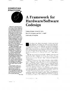
In this section, we briefly describe our in-house framework for multi-FPGA system design. The framework has been designed for integrating multiple cores to aid fast development of complete applications on FPGA platforms. On the hardware side, it provides various standard interfaces, like system bus and DMA controller for plug-n-play user-defined modules. On the software side, it provides a front-end GUI interface which allows the user to provide system specifications, and a back-end synthesis software chain for mapping the desired set of IP blocks onto a target FPGA. The hardware platform of our framework, shown in Fig. 1, consists of a hybrid communication network comprised of a System Local Bus (SLB) and a packet-based on-chip router along with memory controllers, a message-passing interface for inter-FPGA signaling, and other system components. While the SLB serves as the communication backbone within a single FPGA, the router is used to coordinate a secondary channel for both intra- and inter-FPGA communication. The DMA-Manipulate unit handles data movement and packetizing/depacketizing for on-chip and off-chip communications. The Custom Accelerator Module (CAM) is a wrapper for integrating a custom accelerator into the hardware platform. The CAM defines a standard interface between the built-in facilities and an instance of a specific accelerator hardware module. The framework allows the system to be composed of a number of interconnected CAM entities, with each CAM offering custom acceleration to various parts of an algorithm. At the heart of each CAM is an Application Specific Instruction Processor (ASIP) equipped with a hardware Command Fetch unit which facilitates fetching, decoding, and preprocessing of accelerator specific instruction sequences. This ASIP provides the ability for run-time reconfiguration of an accelerator by modifying the instruction/command sequence to be executed. The ASIP processes each command with the help of Command handlers - which are hardware modules that perform instruction specific preprocessing before presenting the command to the accelerator. The framework provides a set of built-in Command Handlers that are useful for many algorithm accelerators. For example - A window fetch handler supports optimized fetching of two dimensional data with programmable column size, number of rows and columns, row and column offset, and inter-row and inter-column strides. Moreover, the command handling capabilities of the CAM can be extended by the inclusion of custom command handlers. These features namely - accelerator specific command sequences and custom handlers - make the framework scalable and flexible for any custom accelerator.
4.
HARDWARE LIBRARY FOR GRIDDING
The gridding interpolation can expressed mathematically as follows: { M −1 ∑ K(ti , sj ) · S(j) if (ti , sj )ϵW T (i) = j=0
f or i = 0, 1, . . . , N − 1 where S is the input array (source), T is the output array (target), K is the kernel function defined on the (source, target) pair (ti , sj ), M and N are the sizes of the input and output arrays respectively and W is the window size. In order to support both arbitrary/nonuniform and regular/uniform trajectories, we have implemented two parameterized hardware modules to accelerate the gridding interpolation • Nonuniform Data Translator (NDT) for arbitrary trajectories • Uniform Data Translator (UDT) for regular trajectories such as Polar or Cartesian
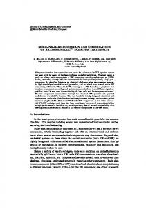
4.1 Nonuniform Data Translator (NDT) A major challenge in handling arbitrarily sampled data is the severe lack of locality which critically affects performance. We address this problem by using a simple Geometric Tiling technique [4][22], to sort the arbitrary samples based on their spatial locality. NDT implements geometric tiling is by a dynamic memory mapping into a linked-list structure where source samples belonging to the same tile are linked together logically as a linked list though they are mapped to noncontiguous addresses. However, each node of the linked list includes a bunch of samples belonging to the same tile, which enables better bandwidth utilization for memory read/write. Tile is the macro-unit of computation. The NDT then fetches a source tile from DRAM by traversing the linked list, generates the target coordinates on-the-fly for the W × W window for each source sample and evaluates the kernel function in the processing element (PE) and writes-back the updated target tile to memory. The NDT assumes the kernel to be a black-box and implements a generic wrapper around it with simple hand-shake signals. This enables plug-and-play of kernel pipelines. Our NDT architecture is shown in Fig 2 and further implementation details can be found in our earlier work [14].
DDR2 Memory DDR2 Memory DDR2 Memory SDRAM
Memory Controller
Embedded Microcontroller
Local On-Chip Memory
Ethernet Interface
System Local Bus Standard Bus Master Interface
Standard Bus Slave Interface
Mailbox DMA and Maniplate
Application Specific Instruction Processor
Datapath Control
Memory Bank 0
Memory Bank 1
Memory Bank 2
Fig. 2. Block diagram of NDT pipeline for 4 PEs
Memory Bank 3
Router
4.2
Custom Accelerator ( Gridding)) ( Gridding Interf-FPGA Interface
Fig. 1. Our framework for FPGA System Design
Uniform Data Translator (UDT)
Since UDT is designed to target regular trajectories, it has the advantage that both the input and output are regular 2D arrays in same/different coordinate systems and hence Geometric Tiling is not required. This saves lot of resources required in handling the linked-list data management and also
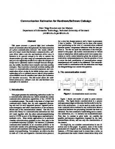
removes the performance bottleneck in reading and writing non-contiguous data. However, the notion of tiling on input and output arrays is still maintained to serve as the macro-unit of computation. To support minimum time-todeployment, we reuse most of the hardware of the NDT. All the hardware used for geometric tiling is disabled and the input and output arrays can be stored in a contiguous memory space. The overall block diagram of the UDT pipeline is shown in Fig 3. The interpolation operation on each tile begins with generation of coordinates for each sample in the output tile, from their respective array indices. A coordinate converter is then used to obtain the equivalent coordinates in the input coordinate system. The coordinate converter is an optional plug-and-play module and is implemented using arithmetic operators and/or using look-up-tables(LUT). Example - For a Cartesian-to-Polar interpolation, the coordinate generator generates polar coordinates and the coordinate converter is computes the equivalent Cartesian coordinate, hence implementing a Polar-to-Cartesian converter. This is followed by the array of PEs to apply the kernel function on the W × W window. However, an accumulation is required over the entire W × W window since all of them correspond to the same output sample. This is implemented by an adder tree to consolidate the results of all the PEs and a floating point accumulator to accumulate the sample updates over time (certain number of cycles). The accumulator is implemented using the dual-stage accumulator architecture[13] for low-latency and minimal stalls. The computed output tile is then written back to the DRAM.
Table 1. Pipeline parameters of various kernel functions generated by the Exploration tool Kernel Gaussian B-spline Exponential
Degree 2 10 2
♯ PEs 4 2 2
LUT depth 1024 16 4096
(BRAMs), one for each column of the LUT, each of depth depth. For every input point x, the index into the LUT is computed first and then this is used to read from all the BRAMs to obtain the coefficients of the Taylor polynomial. The pseudo-code for the Horner’s chiplet is as shown in Fig 4. This computation is performed in a pipelined fashion so that the input rate = output rate = 1 sample per cycle. Computation: index = round( x−LU∆T (0,0) ) c = LU T (index, 0) xminusc = x − c out = LU T (index, degree + 1) f or(j = degree − 1; j >= 0; j = j − 1) out = xminusc ∗ out + LU T (index, j + 1) Fig. 4. Pseudo-code for the Horner’s chiplet The gridding accelerators (NDT and UDT) instantiate a Horner’s chiplet in every PE so that for any specified kernel function, the LUTs can be generated offline and loaded into the BRAMs at run-time. The HDL parameters determines the configuration of the Horner’s chiplet synthesized. This way, the hardware remains the same for any kernel - though changing the LUT entries will realize different kernel functions. This technique provides great flexibility in terms of design-space exploration.
5.2 Design-space exploration
Fig. 3. UDT pipeline with 4 PEs
5. SUPPORT FOR DIFFERENT KERNELS
We have developed an automated design-space exploration tool to optimize the gridding accelerator. As shown in Figure 5, the exploration tool performs an iterative search alongwith the LUT generator to determine the optimal configuration of the kernel - by trading-off the number of parallel PEs and local memory sizes in the accelerator with the depth of the LUTs and the degree of Taylor series expansion - hence exploring the 3-D space of performance-accuracyresource utilization. This flow can be utilized to tune the accuracy or performance of the design by modifying algorithm parameters.
In order to support design-space exploration, we have incorporated a plug-and-play kernel module driven by a lookup-table (LUT) based function evaluation framework. We provide support for a variety of kernel functions such as Gaussian, central B-splines, sinc, Bessel etc. using LUT-based Taylor polynomial evaluation. We provide hardware support for the above technique by implementing a configurable kernel pipeline for Nth degree Taylor polynomial evaluation using Horner’s scheme.
5.1 Kernel Pipeline Generation Many commonly used kernel functions can be evaluated efficiently using Taylor polynomial approximation [7]. We utilize the framework proposed by Deng et. al. [7] for generation of look-up-tables using Taylor polynomial evaluation, which uses the Horner’s scheme for function evaluation. In this work, we augment this LUT-framework by providing hardware support to LUT-based function evaluation and automating the pipeline generation for various kernel functions under specified constraints. We have implemented a hardware pipeline for Nth degree Taylor polynomial evaluation using Horner’s rule and we call this the Horner’s chiplet. The parameters to the Horner’s chiplet are - the degree of Taylor polynomial (degree), sampling interval(δ) and the depth of the LUTs (depth). The pipeline then instantiates degree + 2 on-chip Block RAMs
Fig. 5. Gridding Exploration Tool The kernel functions supported by the LUT-based automation flow are classified into Library kernels and User-defined
kernels as shown below -
Table 2. Systems composed using our Gridding framework and target applications • Library kernels - Gaussian, B-spline, sinc, Bessel, negInput Output Accelerator Application Domain ative exponential, sine, cosine, arctan Arbitrary Cartesian NDT NuFFT SAR, CT Polar Cartesian UDT NuFFT MRI • User-defined kernels - Gabor filter, Gammatone filter Cartesian Polar UDT Polar FT CT The commonly used interpolation kernel functions and trigono- Cartesian Cartesian UDT rescaled FFT DSP metric functions which can be evaluated directly by Taylor polynomial expansion are classified as Library kernels. The MD-DFT IP generator developed by Yu et.al.[20]. The inteKernel automation tool has these functions built-in and can gration of this FFT/IFFT accelerator with our framework is generate optimized LUTs for these functions. Table 1 shows skipped here for brevity. the configuration of the kernel pipelines (degree and depth of Since, the interpolation and Fourier transform are indeLUTs) generated for different kernel functions with similar pendent of each other, it is possible to pipeline these stages. accuracy requirements and the number of PEs that can be This pipeline is at the frame level so that the throughput fit on a Virtex5 FPGA for an NDT implementation. (frame rate) is determined by the stage which has maximum In addition to these, our kernel automation tool supports latency. Since, multiple accelerator modules may not fit on user-defined kernel functions (which can be composed using a single FPGA, a multi-FPGA system would a scalable soluthe library kernels and common mathematical operations). tion. Double buffering is provided on each FPGA to handle In order to support such custom kernels, the kernel automaback-to-back frames. We have developed multi-FPGA systion tool is integrated with a custom compiler which includes tems using the BEE3 platform[5] to realize the above mena parser and a function composition script. The user-defined tioned applications so that each stage is mapped to a different kernel is specified in a file using a MATLAB-like syntax. The FPGA to allow independent operation and customization. compiler parses the file and generates LUTs for the composite On the BEE3, we allocate FPGA 0 to as the gridding acfunctions by using the function composition script. Further celerator and FPGA 1 to be the FFT accelerator. The input details can be found in [21]. frame is loaded into FPGA 0 and any pre-processing such as packetization, format (precision) conversion etc is handled by stream operators. FPGA 0 implements the gridding ac6. SYSTEM INTEGRATION celerator and forwards the result of interpolation to FPGA In this section, we describe the important steps in inte1. FPGA 1 implements the FFT/IFFT accelerator streams grating the gridding accelerators into our development frameout the result frame a another FPGA on the board OR to work to realize an end-system. Firstly, a HDL wrapper that a host machine. An optional deaopdization step (required conforms to the custom accelerator module (CAM) interface in NuFFT) is implemented by a stream operator before forspecification is designed for each gridding accelerator (NDT warding the result frame. We maintain half-duplex commuand UDT). The next and most important step is identifying nication on the inter-FPGA links to maximize throughput of the instructions that the ASIP needs to execute in order to the system. Further, this system can be extended, by making configure and run the accelerator. use of multiple FPGAs for a critical stage like interpolation or mapping some pre-/post- processing algorithms to the un6.1 Command Sequence for the ASIP used FPGAs. This is future work. We discuss a sample command sequence executed by the ASIP to implement the Nonuniform Data Translator (NDT). It includes an initialization command to configure registers in the accelerator (TileInit) and load/store commands for input and output arrays to read/write a tile from DDR memory (LoadTarget, LoadSource and StoreTarget). The hardware support for these commands are provided by command handlers. The LoadTarget and StoreTarget are executed by the built-in window handler since the gridded output array (target) is stored in a contiguous memory space. However, since the arbitrarily sampled input array (source) Fig. 6. A multi-FPGA System for NuFFT is stored in the DDR memory in a linked-list structure, we need to implement a custom handler to support the Load6.3 Automated System Generation Flow Source command. The custom handler includes the logic to traverse the linked-list and fetch a source tile from memory by The automation flow of our framework is shown in Fig. 7. invoking the DMA engine. The custom handler also handles It includes a front-end GUI and a back-end synthesis toolthe TileInit command since this is a customized initialization chain, which can perform rapid system composition from command. algorithm specification. The framework automatically inThe UDT on the other hand does not require such profers control flow, maps CAMs to FPGA resources, instancedures to read from a linked-list structure and hence has a tiates the DMA modules and stream operators, and executes simple custom handler to handle the TileInit command for synthesis scripts necessary to generate bitstreams for each initialization purposes. FPGA in the platform. In addition to hardware, software The command sequence for an NDT includes a executing is generated for the embedded micro-controller (Microblaze) the above commands for each tile in a loop. The software to perform initialization tasks such as configuring routing taintegration with the framework requires the accelerator debles, performing memory allocation, and memory mapping veloper to generate the sequence of commands to be executed for each CAM. The executables for each micro-controller are by the ASIP. The gridding accelerators - NDT and UDT loaded using a JTAG debug interface while the system inineed to execute a constant set of commands for each tile. tialization data is loaded through an Ethernet interface. This software has been developed using C# and integrated into the framework.
6.2 Multi-FPGA mapping on BEE3 Our FPGA platform is BEE3[5], which consists of four Virtex5 LX155T FPGAs with each FPGA connected to up to 16 GB of DDR2 memory. In order to realize end-to-end applications such as NuFFT or Polar FT, the gridding accelerators need to be combined with an FFT accelerator. We utilize the
7.
CASE STUDIES AND RESULTS
In this section, we provide a case study by implementing several end-systems using our framework. Table 2 gives a list of systems generated successfully using our framework along-with possible target applications. For each of the cases listed in the table, several kernel functions from our library and custom kernels mentioned in
The CPU version is an implementation of the open source NFFT library[12] executed on an Intel Xeon dual-core processor running at 2.33 GHz with 4 GB of RAM and running 64 bit Linux OS as reported in [18]. The GPU implementation[18] is for an ATI Firestream 2U graphics card with 1 GB of GDDR3 memory operating on a PC with Intel dual-core processor at 2.13 GHz with 2 GB of RAM running Windows OS. The FPGA version is our previous work [14] and is a single-FPGA implementation of the gridding interpolation on the BEE3 platform operating at 100 MHz. Our FPGA version is a stand-alone two-FPGA system implemented on the BEE3 platform using our framework, with each FPGA operating at 100 MHz.
Fig. 7. The automation flow for system generation Section5, have been successfully generated and validated using our framework. We utilize the trigonometric functions in the library to perform LUT-based coordinate conversion in the UDT. The design parameters that have been validated for both gridding accelerators (NDT and UDT) are • All Library kernels and custom kernels • kernel window size (W) - all integers from 2 to 16 i.e from 2x2 to 16x16 kernel sizes. • image size - up-sampling, down-sampling and same image size for input and output. The case study is split into 4 categories namely - (1) P2C Polar to Cartesian interpolation, (2) C2P - Cartesian to Polar interpolation, (3) N2U - nonuniform to uniform interpolation and (4) C2C - Cartesian to Cartesian interpolation.
7.1 Experimental Setup The algorithm specification - parameters such as input and output data size, arbitrary or known trajectory, kernel function and convolution window - is provided to the front-end GUI of our system. The automated system generation flow is then executed, as shown in Figure 7, to generate the bitstream for the two FPGAs on the BEE3 board. Next, the run-time configuration flow of our tool is executed to generate the configuration for stream operators and the command sequence for each custom accelerator and these are transferred from the host to the BEE3 board through Ethernet. The operating frequency used for each FPGA is 100 MHz. The input data file is loaded into FPGA 0 on the BEE3 board through Ethernet and this begins the computation on the FPGAs. When the result frame is ready, it is sent back to the host through Ethernet.
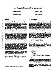
7.2 Results In this section, we provide our test results for several variants generated using our framework and tested on the BEE3 board. Table 3 characterizes test cases and covers cases such as up-sampling, down-sampling, variable kernel window sizes and kernel functions and shows high throughput for each of the variants. It can be seen that the performance deteriorates with increase in input data size, increase in window size and with increase in kernel complexity. Example: Due to higher complexity of the B-spline kernel, lesser number of PEs that can be fit on a device when compared to a Gaussian kernel (Table 1) and hence would be slower, when all other parameters are identical. We also compare the throughput of out multi-FPGA system with existing implementations on CPU, GPU and FPGA.
Fig. 8. Comparison of our NuFFT system on BEE3 with existing CPU[12], GPU[18] and FPGA[14] implementations. The input array sizes are 1282 , 2562 and 5122 with an oversampling factor of 2 per dimension, which makes the output array sizes = 2562 , 5122 and 10242 respectively after gridding. The FFT/IFFT operates on this over-sampled array and provides a result of the same size. The results for each case is the throughput of the entire NuFFT system for a 4×4 Gaussian kernel and is different from the numbers for just the interpolation as compared in [14]. For the CPU and GPU the throughput depends on the entire execution time. However, for our pipelined multi-FPGA system, the FPGA which has higher latency determines the throughput of the system - the gridding accelerator was observed to be the critical stage for most cases. We assume the same while extrapolating the result for our previous FPGA version[14]. In order to normalize the results across all platforms, we use performance-per-Watt (frames-per-sec-per-Watt) as the metric for realistic comparison. The CPU and GPU results are for devices belonging to an older generation and so are both the FPGA versions (Virtex5 FPGA on BEE3 belongs to an older generation and is also one of the smaller devices in it’s family). Hence, a comparison between these platforms is reasonable. Figure 8 shows the comparison for a NuFFT system. Table 4. Relative Performance of our UDT-based NuFFT system compared to existing implementations Input size 128x128 256x256 512x512
CPU[12] 6.756 9 16.71
GPU[18] 0.997 0.762 0.765
FPGA[14] 2.26 2.276 1.54
We make use of the thermal design power (TDP) of the Intel Xeon CPU (65 W)[3] and the AMD Firestream GPU (165 W)[1] as the approximate power consumption of the CPU and GPU platforms. For our multi-FPGA system, we measure the power for each FPGA using Xilinx XPower Analyzer[2] and add them up to obtain the system power (30 W). This compensates for using multiple devices to realize NuFFT for FPGA versions. For our previous FPGA version[14], we measure the power using XPower Analyzer and add the power of the FFT FPGA to obtain the power of a two-FPGA NuFFT system, in order to keep the comparison fair across all platforms (30 W). It must be noted that
Table 3. Throughput of the NuFFT system for various trajectories, data sizes, kernels and window sizes Category
Data Size Input Output
Trajectory Input Output
Accelerator
P2C
128x128
128x128
Polar
Cartesian
UDT
C2P
128x128
128x128
Cartesian
Polar
UDT
N2U
200x168
512x512
Arbitrary
Cartesian
NDT
C2C
512x512
256x256
Cartesian
Cartesian
UDT
across all platforms the power of other system components such as DRAM and peripherals are not included and this is a limitation of the comparison. Figure 8, shows that our NDT-system provides higher performance per-Watt when compared to the existing CPU, GPU and FPGA implementations. The gain w.r.t our previous FPGA version[14] is due to the optimization of tiling parameters using the exploration tool in our system. Since the NDT assumes arbitrary trajectories, it suffers due to low memory-bandwidth utilization due to linked-list data storage. However, our UDT-system makes use of the trajectory information (radial/polar) and organizes data in a contiguous memory space. This leads to better memory-bandwidth utilization and hence it provides much higher throughput when compared to the NDT-system. For the same data sizes, the UDT-system is faster than the NDT-system by 36.5%, 38.6% and 53.9% respectively for input sizes of 1282 , 2562 and 5122 , which shows that using a regular (gridded) trajectory can help improve the throughput of the NuFFT system. Table 4 provides the ratio of throughput of our UDT-based NuFFT system over that of existing NuFFT implementations for radial trajectories. It shows that our mult-FPGA UDTsystem provides a speedup ranging from 6.7X to 16.7 X over the CPU[12] version and between 2.2X to 1.5X over our previous FPGA version[14]. But, our FPGA implementations are still slower compared to the GPU version[18] as shown in Table 4. These results show that our gridding framework can provide a high degree of composability without sacrificing performance, which in essence highlights the advantage of using FPGAs for algorithm-architecture co-design. The above results also show that the performance of the accelerators scale linearly with data size for both our NDT and UDT systems. This framework can be used by an end user to determine the optimal algorithm and architecture specifications for the desired application.
8. CONCLUSION We have presented an algorithm-architecture co-design framework for accelerating gridding using FPGAs. It includes FPGA accelerators for gridding on arbitrary trajectories (NDT) and regular trajectories (UDT) along-with a kernel automation flow which uses look-up-table based Taylor series evaluation to support a variety of kernel functions such as Gaussian, B-spline and Bessel along-with user-defined kernels. This framework has been integrated into our multi-FPGA development platform to realize two-FPGA systems for several variants of NuFFT and Polar FT. These systems have been validated on the BEE3 platform and experimental results show that our framework provides consistent high performance for various trajectories, problemsizes and kernel functions. We demonstrate speedups of up to more than 16X and 2X over existing CPU and FPGA implementations respectively, and up to 5.5 times higher performanceper-watt over an existing GPU implementation.
Acknowledgment This work was supported in part by DARPA DESA program and NSF Awards 0916887 and 0903432. The authors
Kernel
Window
Throughput in fps
Gaussian B-spline exponential Gaussian B-spline exponential Gaussian B-spline Sinc Gaussian B-spline exponential
7 2 9 7 2 9 8 12 4 7 2 9
361 764 135 364 791 136 33 25 36 65 69 34
acknowledge inputs from Dr. Xiaobai Sun and Dr. Nikos Pitsianis of Duke University during the course of this work.
9.
REFERENCES
[1] “AMD Firestream.” [Online]. Available: http://en.wikipedia.org/wiki/AMD_FireStream [2] “Xilinx Xpower analyzer.” [Online]. Available: http://www.xilinx.com/products/design_tools/logic_design/ verification/xpower_an.htm [3] “Intel Xeon 3000 series.” [Online]. Available: http://www.intel.com/Assets/en_US/PDF/datasheet/314915.pdf [4] G. Chen et al. Geometric Tiling for reducing power consumption in structured matrix operations. In IEEE International SOC Conference, pages 113–114, Sept. 2006. [5] J. Davis, C. Thacker, and C. Chang. BEE3: Revitalizing Computer Architecture Research. MSR Technical report, 2009. [6] N. Debroy, N. Pitsianis, and X. Sun. Accelerating Nonuniform fast Fourier transform via reduction in memory access latency. In Proc. of SPIE, volume 7074, 2008. [7] L. Deng, C. Chakrabarti, N. Pitsianis, and X. Sun. Automated optimization of look-up table implementation for function evaluation on FPGAs. In Proc. of SPIE, volume 7444, 2009. [8] C. Farabet et. al. Hardware accelerated Convolutional Neural Networks for synthetic vision systems. ISCAS: Intl. Symp. on Circuits and Systems, pages 257 –260, May. 2010. [9] M. Fenn, S. Kunis, and D. Potts. On the computation of the Polar FFT. Applied and Computational Harmonic Analysis, 22(2):257 – 263, 2007. [10] A. Gregerson. Implementing fast MRI Gridding on GPUs via CUDA. Nvidia Tech. Rep. on Medical Imaging using CUDA, 2008. [11] S. Hadjitheophanous et. al. Towards Hardware Stereoscopic 3D Reconstruction a real-time FPGA computation of the disparity map. In Design, Automation Test in Europe Conference Exhibition (DATE), 2010, pages 1743 –1748, Mar. 2010. [12] J. Keiner, S. Kunis, and D. Potts. NFFT 3.0 - Tutorial. 2007. [13] S. Kestur, J. D. Davis, and O. Williams. BLAS Comparison on FPGA, CPU and GPU. IEEE Comp. Soc. Annual Symposium on VLSI, 0:288–293, 2010. [14] S. Kestur, S. Park, K. M. Irick, and V. Narayanan. Accelerating the Nonuniform fast Fourier transform using FPGAs. Field-Programmable Custom Computing Machines, IEEE Symp. on, 0:19–26, 2010. [15] A. d. C. Lucas, S. Heithecker, and R. Ernst. FlexWAFE - A high-end real-time stream processing library for FPGAs. In DAC ’07: Proceedings of the 44th annual Design Automation Conference, pages 916–921, New York, NY, USA, 2007. ACM. [16] T. Schiwietz, T. Chang, P. Speier, and R. Westermann. MR Image Reconstruction using the GPU. In Proc. of SPIE, volume 6142, page 61423T, 2006. [17] H. Schomberg and J. Timmer. The Gridding method for image reconstruction by Fourier transformation. IEEE Transactions on Medical Imaging, 14(3):596–607, Sep 1995. [18] T. Sorensen, T. Schaeffter, K. Noe, and M. Hansen. Accelerating the Nonequispaced fast Fourier transform on commodity graphics hardware. IEEE Tran. on Medical Imaging, 27(4), April 2008. [19] S. S. Stone et. al. Accelerating advanced MRI Reconstructions on GPUs. J. Parallel Distrib. Comput., 68(10):1307–1318, 2008. [20] C.-L. Yu, C. Chakrabarti, S. Park, and V. Narayanan. Bandwidth-intensive FPGA architecture for multi-dimensional DFT. In Acoustics Speech and Signal Processing (ICASSP), 2010 IEEE Intl. Conf. on, pages 1486 –1489, 2010. [21] Y. Zhang et. al. A special-purpose compiler for look-up table and code generation for function evaluation. In Design, Automation Test in Europe Conference Exhibition (DATE), 2010, pages 1130 –1135, 2010. [22] Y. Zhang et. al.. Exploring parallelization strategies for NuFFT data translation. In Proc. of the ACM Intl. Conf. on Embedded software, pages 187–196. ACM, 2009.