Space Codesign: A SystemC Framework for Fast Exploration of Hardware/Software Systems Luc Filion, Marc-A. Cantin, Laurent Moss, Guy Bois
El Mostapha Aboulhamid
Microelectronics Research Group Ecole Polytechnique Montreal, Canada {filion, cantin, moss, bois}@grm.polymtl.ca
Department of Computers and Operational Research University of Montreal Canada
[email protected]
Abstract—Electronic System Level has brought new abstractions for designing systems, which most designers are not familiar with. The Space Codesign™ SystemC design framework allows designers to easily model hardware/software-based systems, starting from a high level model and refining down to the chip. We propose a rapid system prototyping toolset that permits co-monitoring of specifications, effortless platform exploration for hardware/software partitioning and an automated co-synthesis for rapid FPGA implementation. We demonstrate the methodology by implementing the guiding system of a land rover application. More precisely, we focus on the architecture exploration effort by looking at the partitioning aspects using an IBM CoreConnect OPB bus cycle accurate model, and a MicroBlaze ISS. We collect different mapping results to guide the implementation down to a Xilinx Virtex-II Pro FPGA. Results prove that first working at the system level significantly helps in targeting an efficient hardware/software solution.
I.
INTRODUCTION
Technological innovations have undeniable effects on circuit design complexity; more complex components, including on-chip processors, are integrated, and there are growing customer needs in a narrowing time-to-market era. These issues lead us to the necessity of rethinking how engineers design these circuits. One proposed solution, Electronic System Level (ESL) [1][2], relieves the design pressure by raising the level of abstraction for system modeling, which handles both hardware and software component specifications and captures constraints. ESL offers tremendous possibilities for: •
creating and designing simulation platforms containing processors and coprocessors, communication channels, memories and peripherals, at different levels of abstraction;
•
creating and verifying functional application models;
•
exploring different mappings of a functional application onto a specified architectural platform, to validate specification constraints;
This project is funded by Univalor and by the National Sciences and Engineering Research Council of Canada.
•
refining to lower abstraction levels (e.g. RTL describing pins, events and delta cycles, cycle true timing) and real implementation behaviors, mainly for verification purposes.
ESL brings new possibilities for system design features that positively influence the early phases of the system design flow. Transaction Level Modeling (TLM) [3], a major subset of ESL, mostly insists on the abstraction of the communications between processes in order to accelerate simulations and to provide a reliable analysis of possible system performances. Transactions can be described at different levels of abstraction, from high-level message passing schemes down to typical bus-oriented cycle-by-cycle transactions. Different optimizations are possible depending on the desired simulation accuracy. ESL offers to capture specifications in various ways, based on different in-house designed simulators, graphical tools or programming languages, such as C/C++, SystemC, SystemVerilog or others, or a mix of these solutions. Well known TLM platforms already exist. For instance, the SystemC OSCI TLM package [4], proposes to use layers to classify the different possible abstractions of TLM. Also, SystemC OCP [5] was one of the first works in the field and. Finally, GreenBus [6], which objective is to offer an open source standard interconnect model. Specific needs can also be filled with custom implementations as well: as an example, [7] used SystemC for interfacing an ARM Instruction Set Simulator (ISS) in a SoC implementation. Depending on the level of abstraction selected, simulations will perform better than typical Register Transfer Level (RTL), as shown in [8] and [9]. As said by these authors, many optimizations are possible to increase performance up to a factor of 100, but all affect the accuracy of the simulations, one way or another. Once the ESL design of the application is done, a technique for migrating it to a chip is required. Professional synthesis tools exist but are limited and not open to everyone’s budget. A general recoding phase is required to create hardware blocks, software embedded code, interfaces
and wrappers. Platform-based design is an interesting compromise to avoid having too much to recode and to meet time-to-market constraints. Another rapid prototyping solution is [10], which mixes a set of different tools for simulating and exporting a DSP-based MP3 decoder application with an Atmel processor. This brings interesting results though the methodology is closely coupled to the architecture they use. In this paper, we will look at the value of the Space Codesign toolset for investigating different hardware/software partitions at a bus cycle accurate level, using Space Codesign Simtek, which allows the simulation of a bus cycle accurate version of the specification. We have developed a base platform including the IBM CoreConnect OPB Bus, a library of IP and wrappers and the Xilinx MicroBlaze Instruction Set Simulator (ISS) to emulate a true implementation of a physical platform. All details on bus performances, communication and computation times can be gathered for system performance evaluation using our comonitoring engine. Once all simulations are terminated, an automated co-synthesis process can be used to move down to Xilinx Virtex-II family FPGA. Our technology and development environment will be explained in section II. We used this environment to develop a land rover case study, described in section III and depicted in Figure 1. Details of the simulation and FPGA implementations are given in section IV, while results are discussed in section V. II.
THE SPACE CODESIGN™ TECHNOLOGY
The Space Codesign technology integrates interesting features of electronic system design and simulation, such as drag and drop Hw/Sw partitioning, Hw/Sw co-monitoring and extensive embedded software support with abstracted RTOS complexity. With Space Codesign, the use of the SystemC language is simplified to offer software designers a transparent solution to the lack of software support in SystemC [13]. A simplified application programming interface (API) and a fast communication manager handle all platform communications.
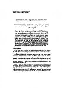
these features in an intuitive design framework. This work originated from SPACE, a platform oriented towards embedded software design, as presented in [12] [13]. Since this publication and as described in this paper, several additions were brought into the SPACE platform, for instance, different instruction set simulators, a bus cycle accurate communication model as well as support for a high abstraction level for software simulations. Moreover, a complete set of tools, including a graphical user interface and co-monitoring were integrated. A. Elix The Space Codesign Elix technology, sometimes described as Programmer’s View [17], contains tools for early stages of the design flow and mainly serves for model or application validation and fast architecture exploration. With Elix, one can, in a straightforward but specialized SystemC environment, create an untimed or timed functional model of the application to implement. Communication between SystemC modules (tasks, threads, user modules, or processes, as preferred) is based on message-passing rendezvous. Using a shared memory to exchange data is also possible. Simple methods are available for communications with modules, or devices (typically slave components) which removes the usual complexity of system-on-chip communication protocols. Channel communications can be untimed or timed according to a user-customized or predefined bus model delay scheme (such as IBM CoreConnect PLB/OPB and ARM AMBA). All simulations bring preliminary results about system performance results and expected hardware/software behavior, as the RTOS and a set of RT tasks are getting integrated into the simulation model. A processor simulator is run as a SystemC module and executes software code on the host machine, for faster results than with bus cycle accurate models. Regardless of the mapping of a specific module, hardware or software, a proper routing of messages is performed by the communication manager. These preliminary results are used to guide lower abstraction design analysis, using Simtek.
The development environment (see Figure 2) integrates Memory
Positioning System
Peripherals
Architecture Component Library
Serial Link
Space Codesign ELIX
U
F
T
space codesign
T
F
Guiding System
Hardware Component
Communication Manager B
IP Component Library
Camera
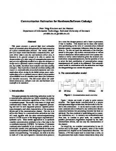
Figure 1. Picture of the land rover revealing its main systems
RTOS
ISS
C
A
Software Task
Software Simulator
Software Task
Space Codesign SIMTEK
Figure 2. The Space Codesign™ Technology
B. Simtek The Space Codesign Simtek technology can simulate a bus cycle accurate replica of a real architecture and its behaviors, including transactions over a specific bus protocol, hardware wrappers to encapsulate custom IPs, a collection of user-accessible platform-specific IP devices, such as memories, timers, controllers and I/Os, as well as instruction set simulators for cycle-accurate software execution. This abstraction produces results that can be analyzed, debugged and monitored. The communication interface of Simtek is the same as Elix’s simplifying the refinement of the specifications. At this stage, users may want to include behavioral timing annotations to better simulate the execution time of the hardware user modules. In fact, annotations can be added at anytime in the design flow: they are simply ignored in an untimed environment. They are also ignored if the module is mapped into software, because of the cycle-accurate execution of software. C. SpaceStudio SpaceStudio is an Eclipse-based development environment [14] for Elix and Simtek. The major advantage for using Eclipse for Electronic Design Automation is that it simplifies third-party tool integration. SpaceStudio (Figure 3) lets designers browse through architecture and component libraries to create a parameterized Elix or Simtek systems. Architectural exploration lets users discover different system configurations (e.g. processors and buses, code mapping on hardware or software, hardware coprocessors, etc.) typically not considered when working at the Register Transfer Level (RTL), because the work implied to experiment with such possibilities is enormous. With the help of SpaceStudio, one can drag and drop SystemC blocks into a hardware-software architecture of its own. Once blocks are mapped by the user, the final architecture and mapping can generate SystemC code and be executed/debugged or cross-debugged. GNUbased debuggers are available for the hardware platform, for SystemC hardware blocks, and for embedded software. Hardware/software co-debugging offers a better interaction with the user and the application being designed, when
searching to understand bugs or problems. System parameter setting is abstracted, kept simple and is centralized in a configuration manager window accessible through wizards. Nearly all platform connections are automatically generated, letting the user focusing on custom connections. This environment permits to rapidly explore hardware/software systems, analyze results, fine tune mapping, regenerate and recompile. D. Co-monitoring SpaceStudio integrates real time co-monitoring tools to maximize programmers’ efficiency. The co-monitoring engine monitors and analyzes the performance of the system. The instrumentation of the platform models and API allows for the collection of metrics on the execution time of hardware user modules and on channel/bus, memory and processor usage. Also, a non-intrusive instrumentation of instruction set simulators monitors RTOS context switches and calls to communication functions. This powers the collection of metrics on the execution time of software user modules and on communications between all user modules, no matter whether the communications are between hardware modules, between software modules or are crossing the hardware/software partition. This co-monitoring is transparent to user code and is automatically adjusted each time a user module is moved from hardware to software (or vice-versa). The collected metrics can be accessed through an API or viewed through a GUI featuring statistical plots, global heatmaps or Gantt charts. For complete technical information about the comonitoring features, please refer to [19]. E. Exporting to FPGA To physically implement Hw/Sw partitioned solutions, we extend the Space Codesign technology to the implementation level. At this stage, hardware (e.g.: muxes, ALUs, decoders, memories) is described in terms of register transfers executed every clock cycle (i.e. the RTL), and software is a sequence of instructions including user target code linked with the RTOS. The transformation from a transactional level (Elix, Simtek) to an implementation level is referred to as hardware/software co-synthesis. It is considered one of the most challenging tasks in embedded design involving system-on-chips. For the case of an implementation based on the Xilinx Virtex II-Pro FPGA, an implementation layer is already provided by the EDK (Embedded Development Kit) from Xilinx. EDK is an application for designing embedded programmable systems based on the Virtex II-Pro. This pre-configured kit includes all the tools and IP required for designing the implementation level of a hardware/software system. Therefore, the Space Codesign technology performs a 3-step automated co-synthesis process between Simtek and EDK: •
Figure 3. The SpaceStudio Development Environment
Software generation is completely automatic. The user software modules/tasks and the RTOS are compiled for the embedded processor. As a first
step, the μC/OS-II RTOS [15] has been selected. μC/OS-II offers all the advantages of a micro-kernel: task preemption, a priority based task scheduler and an interrupt system. As explained in [13], the SystemC function calls are mapped to µC/OS-II equivalents. •
•
The Space Codesign approach is based on IP-reuse. IP are packaged for reuse at different levels of abstraction in the design cycle, such as the functional (SystemC transactional) level and the RTL (VHDL). IP can come from within a company or from thirdparty vendors. Hardware synthesis of user processes can be accomplished with behavioral synthesis tools that transform timed functional models into fully timed RTL models. This synthesis is not performed by the Space Codesign technology, but by external FPGA/IC development tools, such as Forte Designs Cynthesizer [16]. Communications synthesis is also processed. IBM CoreConnect wrappers are required to connect IP to a channel (for the transactional level) and to a bus (for RTL). As RTL IP wrappers called IPIF (Xilinx Intellectual Property InterFace) can be automatically generated using the Xilinx Import Peripheral Wizard, a corresponding timed functional SystemC library of IPIF is reproduced for simulation. Also, a hardware/software communication manager is generated, which provide access to the message passing.
Ultimately, SpaceStudio reads the system configuration created by the user and generates all the required input files for EDK. III.
A LAND ROVER CASE STUDY
As a case study, the guiding system of a rover simulator has been implemented. This system is composed of 5 submodules which can independently be partitioned and mapped to explore, simulate and analyze the performance of different design possibilities. Figure 1 shows a 3D-model of the rover itself. A. Environment Specifications The world the rover evolves in is a virtual world. For sake of simplicity and simulation, we describe this world as an NxN array in which the rover moves. The rover’s location in this array is denoted as Nx and Ny. Also, the rover has an angle ω that characterizes its direction in this world (0 being East, 45° being N-E, and so on). The rover’s mission is to follow a trail traced on the ground, and to never leave this trail. The rover is equipped with a front frame camera that scans the soil; taking pictures of the trail at different moments in time. The rover has a Pulse Width Modulator (PWM)-style engine installed on each front wheel as a forward motion mechanism. The rover can move with a maximal speed Vmax, which is modulated by
the pulse of the left L and right R engines. Once again, for sake of simplicity, we set V = ½(R+L)•Vmax, the speed of the rover at anytime. The rover is controlled by two systems communicating through a RS232 serial link: •
a positioning system that fires camera snapshots and calculates the position Nx and Ny and the angle ω of the rover in the virtual world, within a period of 500 to 1000 ms depending on the operations to accomplish. RS232 transmissions take 0.6ms per byte sent. This system is a fixed test bench which cannot be changed.
•
a guiding system that analyzes the camera images to establish the new direction the rover should take to follow the trail. This system is implemented using the Space Codesign technology. Also, in regards to this new direction, the guiding system calculates the new L and R pulses to apply to the positioning system, and sends it these new pulses.
The execution loops indefinitely. B. Rover Specifications As a case study, the guiding system of a land rover was implemented in SpaceStudio to demonstrate the value-added of the Space Codesign technology and toolset. The guiding system is split into 5 different modules described into Table I. It could have been separated even more or differently or it could be implemented in a complex manner to represent more closely a real guiding system, the purpose here is primarily to demonstrate the methodology. TABLE I. Module Name UART (U) Image Analyzer (I) Angle Calculator (L) Engine Controller (C)
Filter (F) Object Detector (O)
DESCRIPTION OF THE ROVER’S GUIDING SYSTEM Description RS232 UART receiving an 8x8 pixel array from the positioning system’s camera and sending out engine power coefficients and nearby object detection status. Hw/Sw module collecting data from UART, analyzing the image to determine the rover’s direction (ω). Hw/Sw module converting the direction taken ω into an angle α the rover should take in regards with the trail. Hw/Sw module determining, based on current and new direction, as well as previous engine coefficients, the new coefficients to apply to the left and right engines. Reduces speed by a factor 2 when undesired objects are nearby. Hw/Sw module correcting pixels received from the camera. Simply corrects the data to threshold values (e.g. on 8 bits, value 0xFD becomes 0xFF). Hw/Sw module observing the image coming in the guiding system and searching for objects (trees and rocks). Will notify the Engine Controller when such objects are detected.
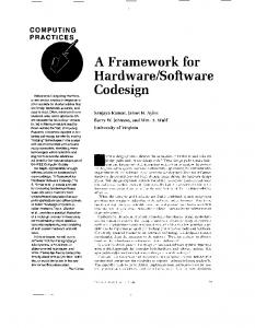
As shown in Figure 4, a UART receives the image information taken from the positioning system. For our purposes, this image is an 8x8 pixel frame: each pixel is a byte representing a soil area crossed or not by the trail. The received image is first read by the Image Analyzer (I), which
Engine ω Controller
32-bit Object Detection Status after 64 PIX
32 bit (α)
Angle Calculator
header / L and R / footer header / Object Status / footer
32 bit (ε)
Object Detector
1 PIX
header / 64 PIX / footer
Image Analyzer
1 PIX
UART
1 PIX
Filter
from/to the positioning system
Figure 4. Rover’s Guiding System Specifications
redirect it to a filter that flattens the pixel values. Then, the analyzer calculates, based on the rover’s direction, the new direction ε the rover should be taking. This value is sent to an Angle Calculator which transforms this ε factor into an angle α. The Angle Calculator can be implemented as a custom look-up table, or more sophisticatedly as a CORDIClike IP, depending on the precision needed. Then, an Engine Controller takes α and based on the current speed V, and direction ω, calculates the new L and R pulses to be applied to the engines. In the meantime, an Object Detector will receive the pixels and search for interfering objects nearby the trail. Information about the presence of objects will be sent to the Engine Controller, which will generate a reduced speed as these objects are getting closer. The positioning system is implemented in a Windows process. The world of the rover itself is plotted as an OpenGL scene. Four threads cover the functionality, one for RS232 communications, one for emulating the camera sweeping the trail, one for calculating the position of the rover based on engine L and R values and a last one for rendering the 3D world. IV.
architecture, and ensures the transparency of exploration, while moving code blocks from hardware to software, and vice-versa. The code contains computation timing annotations in order to model and evaluate the hardware computation time. As previously said, these annotations are ignored for modules partitioned in software. The positioning system uses the last value given by the guiding system to move the rover, as long as a newer value is not provided. This causes an undesirable effect on the rover’s behavior, as this may cause it to be in motion for a too long time, relying on expired data, which can simply lead the rover out of its track. Our experiments have demonstrated that when the guiding system responds in more than 1000ms, the rover cannot properly handle sharp curves, or tend to oscillate in its path. This value is considered a hard constraint in our design. B. FPGA Implementation The target hardware platform is the Xilinx Multimedia board [18]. The board includes a Virtex-II XC2V2000FF896 FPGA, five memory banks of 512x32 bits each directly accessible from the pin out of the FPGA, two clock sources and several I/O interfaces. For our application, the whole system is implemented in the FPGA and clocked with the 27MHz frequency source. The RS232 port is set at 57600 baud and is used for the communications between the positioning and guiding systems. The JTAG interface allows downloading the bitstream to configure the FPGA. The XC2V2000 FPGA is composed of 10752 slices, elementary logic unit combined together to perform the desired system functionality. The MicroBlaze soft-processor IP and several IP provided by Xilinx, such as the timer, the UART Lite, the interrupt controller, the external memory controller and the OPB bus are implemented within these slices, as depicted in Figure 5. The remaining slices are free
IMPLEMENTATION DETAILS OF THE GUIDING SYSTEM
Our goal is to implement different hardware/software configurations of the land rover’s guiding system. All software partition code will be compiled on µC/OS-II with our SystemC to OS conversion mechanism.
MicroBlaze Processor
Timer
Sw Tasks and RTOS
Interface
Interface
Module
Module
OPB Bus
Interface
Messages intended for software-mapped modules (tasks) are sent to the communication manager which is connected to the bus that fires an interrupt to the processor when a new message comes in. The processor then collects the message. This implementation removes the need for shared memory
Interrupt Controller
Module
A. Simulation Implementation The UART is considered as a device in the system, and thus, it is fixed into the hardware partition. All other modules can move from hardware to software, independently. Moreover, the Xilinx UART-Lite IP has a 16-byte buffer. A UART was used instead of a TCP/IP link for the somewhat low data rate of the communications. Nevertheless, the method is scalable to any rate/type of communications.
Hw/Sw Comm. Manager
SDRAM Controller
FPGA Limit External Memory Banks
On Chip Data Memory Segment
UART Lite
FPGA Limit RS232
Figure 5. Architecture generated for FPGA, after simulation
to implement user modules. The MicroBlaze program to execute is stored in the external memory banks. This increases the cycle latency required to execute an operation to 14 cycles. V.
RESULTS
Simulation results are taken from an IBM IntelliStation M Pro, with dual core P4 clocked at 2.80GHz, with 2GB of RAM. Windows XP Professional 2002-SP2 is installed. A. Partitioning Capabilities With the use of SpaceStudio, we have been able to quickly explore the different hardware/software partitions exposed in Table III. While 32 partitions are theoretically available, not all of them are worth exploring for different reasons. An all-hardware partition (No.1) and all-software solution (No.7) are worth testing as they represent the opposite sides of the spectrum of solutions. Five solutions in between were explored. Also, we tend to focus the exploration on the Image Analyzer (I) module, since it has the main role in this simulation: it polls the UART for new data, propagates the information to surrounding modules and computes some data as well. The expectation would be that this module should be in hardware, although its presence as a lone module in the software partition can bring interesting numbers on the processor capabilities. B. Simulation Results for Simtek Using Simtek, a Xilinx MicroBlaze ISS connected to a CoreConnect OPB bus model and peripherals were instantiated. Memory accesses are set to 14 cycles, to reproduce FPGA external SDRAM latency. The clock frequency is set of 27 MHz. The co-monitoring engine can separately evaluate the time hardware and software modules spent on computation and on communication. The results of Table II show that the Filter (F) and Image Analyzer (I) have a much better comparative performance when partitioned in hardware rather than software, because a lot of operations can be parallelized. However, performance of software modules may contradict these early assumptions. TABLE II. Module Acronym Ca F I L O
the required cycles for simulating one frame (that is one loop of the Figure 4 model). Not surprisingly, placing more modules in software increases the overall simulation time, as more sequential operations are executed. The point here is to focus on an acceptable solution that meets performance constraints and needs. TABLE III. No 1 2 3 4 5 6 7
Simulation with Simtek – Raw Computation SW latency (Mcycles) 39 3.405 320 11.543 388 18.066 10 0.208 35 5.672 a. Module Acronym Letters are listed in Table I
The architecture exploration will allow to map blocks onto the processor or to connect them directly on the shared OPB bus. Table III shows the proposed partitions along with
HW Partition CFILOa CFLO FIO IF IO I ∅
SW Partition ∅ I CL CLO CFL CFLO CFILO
Millions of Cycles 0.184 11.778 20.268 22.188 24.008 29.080 38.520
a. Module Acronym Letters are listed in Table I
The following bullets discuss about the different partitions shown in Table III. •
Solution No.1 (all hardware) shows fast bus transactions: reading 16 pixels from the UART takes 3µs, which complies with the input data rate constraint.
•
Solution No.2 explores the Image Analyzer (I) module in software, alone. As can be seen, this module requires a large amount of processing.
•
Solution No.3 explores small complexity modules into software. Since many transactions stream outside of the processor, requiring many context switches, the cycle count is higher than what could have been expected.
•
Attention is brought to solution No.4, which has Image Analyzer (I) in hardware and Object Detector (O) in software. This solution causes the Image Analyzer to send messages (i.e. triggers interrupts) to the processor at a rate it cannot handle, unless we deliberately insert a proper delay between every single communication, which we did. Nevertheless, only 10% (~2M cycles) differs from the previous solution.
•
In solutions No.5 to No.7, modules are switched progressively from the hardware partition to the software partition, causing the system to require more cycles to execute (and more time to simulate, though the performance remains constant). While solution No.5 is good, solutions No.6 and No.7 cannot be considered, as their response comes after 1000ms, i.e. more than 27Mcycles. Indeed, the comonitoring of solution No.7 indicates that 100ms delays are introduced between some UART accesses, a situation that does not comply with the 0.6ms/byte requirement; data are overwritten into the
SIMULATION CYCLES PER MODULE / ONE FRAME HW latency (cycles)
SYSTEM PARTITIONS SIMULATED / ONE FRAME
UART. Figure 6, obtained from the co-monitoring engine, shows the intensity of data exchanged between the Image Analyzer (I) and the UART: inter-peaks zeros are wait states because of context switches. C. Results for FPGA Physical Implementation Table IV presents the processing time and area required for each user VHDL module. It shows that taking time measurements of hardware blocks or software tasks running on FPGA rather than in simulation is laborious and brings distorted numbers. Furthermore, Table IV presents the area needed by a MicroBlaze package, including the MicroBlaze processor itself and all its supporting components, i.e. a timer, an interrupt controller, an external memory controller and the communication manager. When at least one module is mapped into software, the whole MicroBlaze package is inserted in the final system, increasing the total area. TABLE IV.
FPGA LATENCIES AND AREAS PER MODULE / ONE FRAME FPGA Implementation
Module
HW raw computation latency (cycles)
HW communication latency (Mcycles)
SW total latency (Mcycles)
Area when on bus (slices)
C F I L O MicroBlaze
39 320 388 10 35 N/A
0.318 2.628 2.854 0.114 3.704 N/A
3.285 12.519 17.955 0.193 6.115 N/A
1245 1193 1567 1145 1173 1929
From Table IV, it can be observed that most of the computation time is spent in the Image Analyzer (I) and the Filter (F) modules, which agrees with Table II. Hardware raw computation times can be obtained by implementing a counter into each module. Another technique was tried, in order to include the time for communications, but it brought some difficulties. For peeking at a hardware block in execution, we mapped all other modules into software and the Xilinx timer access function was used to get the current tick count before and after the hardware block ran. The method required to fire an interrupt, which caused many software context switches that significantly affected the results: in this example, a context switch processing takes about 57,000 cycles. In any case, this gives a rough estimate of the hardware communication times. As for software latency, this timer technique is totally applicable, because only it affects the results by a couple hundred cycles per timer access. Because all modules were mapped into software, no undesired context switching occurred. A difference of about 8% is observed between simulation and FPGA execution. Finally, areas are all alike and rejection of one module or another based on area is not a key factor for this application. However, placing more modules in software frees area, as only one MicroBlaze package is required.
Figure 6. One frame data exchange. Horizontal axis is the total time of simulation while vertical cumulates communication times between UART and SW-partitioned Image Analyzer.
Table V takes back the mapping configurations explored in simulation. The table shows the time needed to process one frame and the required FPGA resources to implement the seven considered configurations. In general, higher the number of modules mapped into hardware is, less time is required to process one frame, and higher is the FPGA resources utilization. Nevertheless, configuration No.2 has the highest hardware cost since the number of slices to implement the Image Analyzer module (I) (1567 slices) is less than the requirement to implement a MicroBlaze and all its supporting components (1929 slices). TABLE V. No 1 2 3 4 5 6 7
HW Partition CFILO CFLO FIO IF IO I ∅
SYSTEM PARTITIONS FPGA IMPLEMENTED / ONE FRAME SW Partition ∅ I CL CLO CFL CFLO CFILO
Total Latency (Mcycles) 0.318 9.828 18.198 23.139 26.757 31.509 35.127
Total Area (slices (%)) 6390 (59.4%) 6685 (62.2%) 5929 (55.1%) 4756 (44.2%) 4736 (44.0%) 3563 (33.1%) 1929 (17.9%)
In this case study, all user modules can be mapped in hardware (refer to Table V, No.1). However, in such applications, mapping all modules in hardware may need FPGA resources larger than it can afford. It is then important to determine which user module has the least impact on the pure performances once mapped into software. On the other hand, mapping all user modules in software may not meet performance criteria for some applications. With SpaceStudio, it is easy to determine which module(s) need to be implemented in hardware. For example in our case study, it can be observed that is more appropriate to map the Filter (F) in hardware than the Object Detector (O) (refer to configurations No.4 and No.5). Once mapped in hardware, the Filter module (F) brings a reduction of 3.6M cycles compared with the Object Detector (O) with only 20 slices more, which is a time reduction of 13.5% with an 0.2% increase of hardware resources. Solution No.5 respects
the 27M cycles for 1 single frame and has minimal area cost, therefore, it represents a fair choice for final implementation. Finally, a comparison between the simulation cycles of Simtek and the observed results of the implementation on FPGA show, for simulating a whole frame, an average difference of about 10%, which provides a fairly good estimation, considering the short time spent to explore architectures in simulation (about 2 weeks) versus the time spent trying the same directly on the FPGA (about 6 weeks). VI.
FUTURE WORK AND CONCLUSION
The Space Codesign framework has shown that it is worthwhile and efficient starting designs from TLM simulations in SystemC to explore different partition mappings and solutions rather than directly starting implementation at the RTL level or on FPGA. Our comonitoring engine helps in making these decisions by providing summarized or detailed statistics about the simulations. Design space exploration usually leads designers to take enlightened implementation decisions. The Space Codesign technology offers a pleasant environment to effortlessly explore hardware/software partitions, by using drag and drop partitioning from the development environment SpaceStudio. Future work will include demonstration of the scalability of the technique by developing systems with data-intensive applications and heterogeneous multi-processor solutions. Also, we could provide an area estimation tool with Elix and Simtek. In shorter terms we intend providing more detailed results for software simulations. Also, we will extend the partitioning results to the Elix technology and improve the hardware platform timing annotations. ACKNOWLEDGMENT The authors cheerfully thank Sébastien Fontaine who fervently helped for presenting the results, and also the project team, always hardworking: Benoit Pilote, Jérôme Chevalier, Maxime De Nanclas, Ahmed Faiz and Cédric Migliorini. REFERENCES [1]
[2]
V. Perrier “A look inside electronic system level (ESL) design”, EEdesign.com. March 2004. Online @ http://www.embedded.com/ showArticle.jhtml?articleID=18402916 (last visited September 2006). K. Keutzer, S. Malik, A. R. Newton, J. M. Rabaey, A. SangiovanniVincentelli. “System-Level Design: Orthogonalization of Concerns and Platform-Based Design.” IEEE Transactions on Computer-Aided
[3] [4] [5]
[6]
[7] [8]
[9]
[10]
[11]
[12]
[13]
[14] [15] [16] [17] [18] [19]
Design and Integrated Circuits and Systems. Vol. 19, No. 12, December 2000. pp 1523-1543. L. Cai L., D. Gajski “Transaction Level Modeling: An Overview” CODES. Oct. 2003. A. Rose, S. Swan, J. Pierce, J.-M. Fernandez. “Transaction Level Modeling in SystemC” Draft 1. http://www.systemc.org. A. Haverinen, M. Leclercq, N. Weyrich, D. Wingard. “SystemC based SoC Communication Modeling for the OCP Protocol” Whitepaper. 2002. http://www.ocp-ip.org . W. Klingauf, R. Guenzel, O. Bringmann, P. Parfuntseu, M. Burton. “GreenBus – A Generic Interconnect Fabric for Transaction Level Modelling”. Proceedings of the 43rd annual conference on Design automation. DAC 2006, San Francisco, USA, pp 905-910. S. Pasricha. “Transaction Level Modeling of SoC with SystemC 2.0”. Pasricha - Synopsys User Group Conference, 2002. T. Rissa, A. Donlin, W. Luk. “Evaluation of SystemC Modelling of Reconfigurable Embedded Systems”. Proceedings of the Design, Automation and Test in Europe Conference and Exhibition. DATE 2005. Munich, Germany. M. Caldari, M. Conti, M. Coppola, S. Curaba, L. Pieralisi, C. Turchetti. “Transaction-Level Models for AMBA Bus Architecture Using SystemC 2.0”. Proceedings of the Design,Automation and Test in Europe Conference and Exhibition. DATE 2003. J. Bieger, S. A. Huss, M. Jung, S. Klaus, T. Steininger. “Rapid Prototyping for Configurable System-on-a-Chip Platforms: A Simulation Based Approach”. Proceedings of the 17th International Conference on International Conference on VLSI Design (VLSID 2004). pp 577- 582. R. Goering “System-level design coming for software” EETimes Print Front September 2006. (last visited September 2006). http://www.eetimes.com/issue/fp/showArticle.jhtml?articleID=19250 1051 O. Benny, M. Rondonneau, J. Chevalier, G. Bois, E. M. Aboulhamid, and F.-R. Boyer, "SoC Software Refinement Approach for a SystemC Platform," Proc. DVCon 2004, Design & Verification Conference & Exhibition, San Jose, CA, March, 2004, pp. 7 pages. J. Chevalier, M. de Nanclas, L. Filion, O. Benny, M. Rondonneau, G. Bois, E.M. Aboulhamid. “A SystemC Refinement Methodology for Embedded Software”. Design and Test of Computers. March/April 2006 (Vol. 23, No. 2 ) pp. 148-158. Eclipse – an open development platform. http://www.eclipse.org/ Labrosse J. J. “Microc/OS II: The Real-Time Kernel”. 2nd Ed. CMP Books. 2002. 605 pages Forte Design Systems. Cynthesizer 3.0. http://www.forteds.com/highleveldesign/index.asp A. Donlin “Transaction Level Modeling: Flows and Use Models”. CODES+ISSS’04, September 2004. Xilinx Inc. Multimedia Board. http://www.xilinx.com/products/boards/multimedia/ L. Moss, M. de Nanclas, L. Filion, S. Fontaine, G. Bois, E.M. Aboulhamid. “Seamless Hardware/Software Performance CoMonitoring in a Codesign Simulation Environment with RTOS Support”. Design, Automation and Test in Europe Conference and Exhibition (DATE’07), 6 pages. “In Press”.