software development project may need to manage different versions of the system model ... class diagram comparison and offer the new approach on a subject. ..... [9] Harmon, P, Wolf, C. The State of Business Process. Management 2014 ...
ICSEA 2015 : The Tenth International Conference on Software Engineering Advances
An Approach to Compare UML Class Diagrams Based on Semantical Features of Their Elements Oksana Nikiforova, Konstantins Gusarovs, Ludmila Kozacenko, Dace Ahilcenoka, Dainis Ungurs Faculty of Computer Science and Information Technology Riga Technical University Riga, Latvia {oksana.nikiforova, konstantins.gusarovs, ludmila.kozacenko, dace.ahilcenoka, dainis.ungurs}@rtu.lv Abstract —Models are widely used in software engineering, where the Unified Modelling Language (UML) class diagrams are the top notation to present the core system structure and serves as the main artefact for analysis, design and implementation of the software system. As far as the UML class diagram is created at the different levels of abstraction, fluently modified and used to present different aspects of the system, the software development project may need to manage different versions of the system model presented in that notation. Therefore, it is very important to have an ability to compare different versions of the UML class diagram created for the same system to avoid duplicates, missings and contradictions in the whole system model. In this paper an approach to do such a comparison is being described and tested on a simple example in comparison with some other similar methods. We analyze some of the existing methods and algorithms used for the UML class diagram comparison and offer the new approach on a subject. The approach offered in this paper is based on the evaluation of semantical features of the UML class diagram elements. Keywords – semi-automatic diagram comparison; conformity verification; UML class diagram.
I.
INTRODUCTION
Nowadays, system development starts with a modeling of a problem domain and then of a software domain. The benefit of using the models is that it helps to solve the complexity of systems by showing only required information and representing it in a graphical manner comprehensible to a human. Since modeling is used from the early software development phases, the system engineers can have a large amount of the model’s versions representing the system from the different aspects, in different development stages and versions. In order to evaluate the differences between these model versions, one needs to compare them. These differences allow detecting the incomplete functionality, errors or lack of correspondence. For example, when it is necessary to find out if the model specified in documentation complies with the actual system model, which can be generated automatically from the code. In addition, the comparison of the model versions can be used to analyze the differences between the implemented systems and systems under development, thus identifying the reusable components [1]. One more task where model comparison is of high importance is evaluation of model transformation itself.
Copyright (c) IARIA, 2015.
ISBN: 978-1-61208-438-1
During the software development, the models can be created manually [2], generated from the code [3] or transformed from the other models, e.g., using the transformation approaches presented in [4]-[6]. The model comparison can be used to evaluate the models obtained automatically (generated from the code or via transformation) so that the model generation or transformation method can be validated [7][8]. In this case, a formal approach to the model comparison can serve to evaluate the method proposed and used for automatic generation of some diagram or model transformation. The manual model comparison is a time consuming and complicated task. Therefore, the automatic comparison is preferred. Commonly, different graphical notations are used to describe the system or its part in different levels of abstraction. There are many notations that can be used to model system [9]. It can delay an evolution of the comparison methods used for the model conformity verification, because we would need many comparison methods specific to the certain modeling language. Still, it is possible to try to introduce the method for evaluation of the most popular modeling language. One of these notations is the UML, which is recognized as an industry standard proposed by the Object Management Group [10]. The UML is designed to model and visualize the system from the different point of views, such as the system structure and behavior. The most widely used UML diagram is the class diagram, therefore the main focus of this paper is turned to the UML class diagrams and their comparison abilities. The goal of this paper is to propose an approach for the comparison of the UML class diagrams adoptable also for the other modeling languages, which have the similar infrastructure as UML. The rest of the paper is structured as follows. The second section describes related work on existing model comparison methods and techniques. The third section explains the comparison approach offered by the authors. The proposed approach is demonstrated on an abstract example in the fourth section, where the defined calculations are applied to compare two class diagrams containing all the possible features to show the essence of the approach. The conclusions are made in the fifth section. II.
RELATED WORK
In order to cover the state of the art in the existing methods for UML class diagram comparison, the authors conducted a research using online libraries, such as IEEE,
147
ICSEA 2015 : The Tenth International Conference on Software Engineering Advances
EBSCO and Springer Link. Several methods exist in the area and approaches proposed differ in the results obtained from an UML-model comparison process (e.g [1][11]-[13]). Analyzing those methods we have searched for the ones that are providing the numerical metrics that describe model differences in order to compare those to our proposed approach. As a result two similar methods were selected for evaluation. The first method similar to proposed by the authors is described by Mojeeb Al-Rhman Al-Khiaty and Moataz Ahmed [1]. The method is based upon several similarity metrics described as follows: Shallow Lexical Name Similarity Metric (NS) – describes the difference between two semantically similar class names. Attribute Similarity Metric (ASim) – describes the difference between two sets of class attributes. Operations’ Similarity Metric (OSim) – describes the difference between two sets of operations (methods). Internal Similarity Metric (IS) – utilizes two previously defined ASim and OSim metrics in order to estimate the difference between two classes. Neighborhood Similarity Metric (NHS) – describes the difference of class neighborhoods (i.e., related classes) using special relation type comparison table. All metrics defined above are being used to produce a similarity score for pairs of elements in the compared class diagrams. The second method described in this paper is proposed by D. H. Qiu, H. Li, and J. L. Sun [11]. The authors of this paper propose not to compare class names while estimating the difference between two class models since it may result in a rather big impact to the comparison results. Similarly to [1], this method uses attribute and operation sets to define difference between compared class structure, however, relation similarity estimation is different – focusing on three types of class relations defined by the authors: Inheritance – which includes both inheritance and realization. Method coupling – when class A uses methods of class B that is commonly referred as a dependency. Data coupling – when class A uses publicly available data of class B, as well as cases of aggregation and composition. As a result, a single number describing two class diagram similarity is obtained. III.
PROPOSED COMPARISON METHOD
In order to successfully compare two different UML class diagrams, it is necessary to take into account its elements, relations between them, as well as semantical information of those. Since the UML class diagrams are usually produced by the human system analysts, it is possible that two elements that are equal by their semantics have different names, which makes the naive approach not applicable. The authors state that the UML class diagram comparison should also be done by a human (however, it is possible to introduce some kind of
Copyright (c) IARIA, 2015.
ISBN: 978-1-61208-438-1
automation) after the semantically equal element pairs are identified. The proposed method compares the following of the UML class diagram elements [3]: Classes (and interfaces). Class attributes. Methods. Relations between elements. For each of those elements the following comparison algorithm is defined: 1. Pair the elements from two diagrams according to their semantical meaning. This step of the algorithm requires human involvement. 2. Calculate distance between the elements of each pair. 3. Add the calculated distance to a model difference vector that is used to estimate the final difference. After these steps are done, a vector containing distances between appropriate element pairs is constructed, and its length is being estimated to receive the resulting difference. The distances between the classes and interfaces are calculated using Table I. TABLE I.
CLASS AND INTERFACE DISTANCES
Criteria In both models semantically equal elements with same names are present In both models semantically equal elements are present, however, their names differ One of the model doesn’t contain semantically equal class from another model
Distance 0 0.5 1
In order to calculate the distances between the class attributes, it is necessary to construct the temporary vector shown in formula 1 and estimate its length (described in details in Table II). (1) TABLE II.
Element a
ELEMENTS OF COMPARISON VECTOR FOR CLASS ATTRIBUTES
s
Criteria Difference between access modifiers of appropriate class attributes Static modifier flag
n
Name difference
t
Attribute difference
type
Value 0 for the same, 1 for different
0 if both attributes share the same static modifier, 1 otherwise 0 for the same attribute names, 1 for different 0 for the same type, 1 for different
In case one of the attributes is present only in one of the compared class diagrams (or when the enclosing class is not present), all the elements of attribute difference vector are set
148
ICSEA 2015 : The Tenth International Conference on Software Engineering Advances
to 1. After the construction of the vector, its length is being calculated providing distance value between attributes. The distance calculation between the class methods also requires the construction of temporary vector (formula 2) and its length estimation (described in details in Table III):
After the comparison of the identified element pairs, set of distances between those is received. This set of values is then converted into n-dimension model difference vector, where n is a number of the identified element pairs. The final model difference estimation is equal to the length of the model difference vector and is represented by a single number.
(2) TABLE III.
TABLE IV.
ELEMENTS OF COMPARISON VECTOR FOR CLASS METHODS
Element o
Criteria Owning difference
a s
Difference between access modifiers Static modifier flag
n
Name difference
p
Difference between method arguments
r
Difference between return type
class
Value If a method is defined in a semantically equal classes (interfaces) – 0, 1 otherwise 0 for the same, 1 for different 0 if both methods share the same static modifier, 1 otherwise 0 for the same method names, 1 for different 0.2 for each mismatching attribute type, 0.5 for missing argument (see explanation below) 0 when return type is semantically equal, 1 otherwise.
The difference between the method arguments is calculated basing on the types of arguments. In order to calculate this difference, the arguments of the compared methods are paired by their semantical meaning, and then for the each pair the types of the arguments are being compared. If the types mismatch, 0.2 is being added to the difference. In case when the argument is present only in one of the compared methods, the difference is increased by 0.5 thus giving the formula 3. (3) Where: at – number of the method arguments with mismatching types. am – number of the cases when the method argument is present only in the one of compared UML class diagrams. The argument order is not being taken into account, since the argument pairing by their semantical meaning is performed before the actual difference calculation. The relation comparison is also done using the difference vector shown in formula 4 that is described as follows with the detailed explanation given in the Table IV. (4)
Copyright (c) IARIA, 2015.
ISBN: 978-1-61208-438-1
Element s
RELATION COMPARISON VECTOR ELEMENTS
y
Criteria Relation source difference – denotes if relation is outgoing from the semantically equal class in both models Relation target difference – denotes if relation is incoming into the semantically equal class in both models Relation type difference
m
Multiplicity difference
t
Value 0 for the same class, 1 for different
0 for the same class, 1 for different
0 if both relations are of the same type, 1 otherwise 0 if relations have the same multiplicity, 1 otherwise
In all the cases above, when the n-dimensional vector length is mentioned, it is calculated by the following formula 5 (Euclidian distance).
(5)
Thus, the final output of the proposed UML class diagram comparison method is the number which defines the distance between the diagrams that are compared. The larger is the resulting number, the more differences are noted. Such information is useful when developing model transformations with the target of the UML class diagram or code – thus generated model/code can be compared to the ones produced by a human in order to define the quality of transformation. The shorter is the distance from the generated class diagram to the etalon, the higher is a quality of the defined transformation. It is also possible to use the model difference vector in order to detect changes when working with several versions of the same UML class diagram. In such case each element of this vector determines the amount of changes for each of the UML class diagram elements that are being compared. It is also possible to apply different weights to the different elements of the model difference vector however there is no universal solution for the weighting in this case.
149
ICSEA 2015 : The Tenth International Conference on Software Engineering Advances
IV.
APROBATION OF THE METHOD
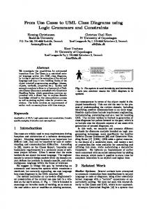
In order to test the proposed UML class diagram comparison method, three simple UML class diagrams were created. The diagrams contain 2 classes: Point and Line, and describe the abstract geometrical domain. The class Line consists of two points – the start and the end. The first class diagram is shown in Figure 1 and is used as a reference diagram in the comparison. It means that two other diagrams are compared vice versa of this.
methods Point.distance() and the Line.length() respectively. Also, the arguments of the method Point.distanceFrom()are different in the same way as in the diagram in Figure 2.
Figure 3. Class model with different return type (Diagram 3).
Figure 1. Reference UML class model (Diagram 1).
The second class diagram shown in Figure 2 is different from the first one in two aspects: 1) the class name –Point is renamed to Coordinates 2) the difference in arguments of the method Coordinates.distanceFrom().
A. Comparison of Diagram 1 and Diagram 2 Comparison of the UML class diagrams using the approach offered in this paper requires the identification of the element pairs and calculation of the distance between them. In this paper the accessor and mutator methods are being omitted since the distance between them is equal to 0 due to equality of the names, access modifiers, return types and signatures. The details in comparison of the element pairs and the distance are shown in Table V. The estimation of the model difference vector for those two models gives the final model difference equal to 1.5811 (formula 6). (6)
B. Comparison of Diagram 1 and Diagram 3 The elements of the diagram difference vector for the UML class diagrams 2 and 3 as well, as appropriate diagram element pairs (those that are responsible for these element values) are shown in Table VI. The estimation of the diagram difference vector for those two models gives the final model difference equal to 2.0616 (formula 7).
Figure 2. Class model with renamed class (Diagram 2).
(7)
The third diagram is shown in Figure 3, while it shares the same class names it has different return types for methods that are used to calculate distance between two points – the
Copyright (c) IARIA, 2015.
ISBN: 978-1-61208-438-1
150
ICSEA 2015 : The Tenth International Conference on Software Engineering Advances
TABLE V.
ELEMENT PAIR COMPARISON FOR DIAGRAM 1 AND DIAGRAM 2
Diagram 1 Element
Diagram 2 Element
Point Point.x Point.y Point.distance() Point.distanceFrom() Line Line.start Line.end Line.length() Aggregation (Line -> Point) TABLE VI.
0
Diagram 3 Element
Distance
Point Point.x Point.y Point.distance() Point.distanceFrom() Line Line.start Line.end Line.length() Aggregation (Line -> Point)
C. Result Analysis The analysis of the results achieved proves to be as expected: Diagram 1 and Diagram 2 are actually less different then Diagram 1 and Diagram 3 despite the fact that in Diagram 2 the class Point has the different name. This is due to the class Point/Coordinates itself is semantically the same in both Diagrams 1 and 2, i.e., with the same attributes and methods. Therefore, the impact on the class difference is much slighter. Such results seem to be relevant in case of studying the output of the human-produced class diagrams that are commonly used in the first stages of a software development process. Since the human system analysts may (and usually will) use different names for the similar concepts when modeling the problem domain class, the name difference should affect comparison results in a slightly lower way than the structural difference of compared models. In comparison to the proposed approach method described by Mojeeb Al-Rhman Al-Khiaty and Moataz Ahmed [1] tends to define more differences between models in example case – due to use of Longest Common Subsequence (LCS) algorithm when comparing the names of the model elements. Exact numbers aren’t provided in the paper due to different scales of the numbers. D. H. Qiu’s, H. Li’s, and J. L. Sun’s method [11] was also compared to the proposed one. In this case name differences aren’t taken into account thus method shows less differences
Copyright (c) IARIA, 2015.
0.5
ELEMENT PAIR COMPARISON FOR MODELS 1 AND DIAGRAM 3
Diagram 1 Element Point Point.x Point.y Point.distance() Point.distanceFrom() Line Line.start Line.end Line.length() Aggregation (Line -> Point)
Distance
Coordinates Coordinates.x Coordinates.y Coordinates.distance() Coordinates.distanceFrom() Line Line.start Line.end Line.length() Aggregation (Line -> Coordinates)
ISBN: 978-1-61208-438-1
0
0
between compared class models – only ones that are result of inner structure mismatch. Thus we can conclude that proposed method is somewhere between those two eliminating the drawbacks of former. V.
CONCLUSION
One of the recent trends used in the iterative software development is a model presenting the system at the different levels of abstraction. As the system model is created at the different stages of the system development and in the different manner – manually or generating from some text information or other model, there is a need to evaluate the current version of some diagram and compare it to the other diagrams created at the previous stages of the project or in the different way of the modelling. The most widely used notation in the modern software development projects is the UML, and its class diagram is applicable at the different abstraction levels of the software system development. Therefore, the most important task of the comparison of two models is exactly the UML class diagram comparison and evaluation. An effort to find a suitable approach to compare two UML class diagrams in advanced scientific databases gave the authors very pure results. Namely, there are a very few methods how to compare the UML class diagrams and they don’t provide a valuable result.
151
ICSEA 2015 : The Tenth International Conference on Software Engineering Advances
The authors of this paper are working on the development of the model transformation method for the generation of the UML class diagram from the so-called two-hemisphere model [5]. There is a need to compare the received UML class diagram with the diagram created manually during the software development process to approve the quality of the transformation offered. This is one more reason to turn the attention to searching for existing approach to the UML diagram comparison or inventing a new one. The comparison approach offered in this paper is based on the semantical features of the elements presented in the UML class diagram and takes into consideration the structural facilities of the diagram as they are more essential than, e.g., the name differences. The essence of the approach is based on the identification of the semantically same or similar pairs of the diagram elements and further evaluation of the distance between them. The comparison approach offered in this paper is applied to the several examples to compare the class diagrams created in the different manner, but, due to the length limitations of the paper, only the abstract example is demonstrated here. The application of the comparison approach to the evaluation of the transformations defined by the two-hemisphere modeldriven approach is stated as a direction for the future research.
[7]
[8]
[9]
[10]
[11]
[12]
[13]
Kriouile A., Gadi T., Balouki Y. IM to PIM Transformation: A criteria Based Evaluation. International Journal of Computer Technology & Applications. 2013, vol.4, no.4, pp.616-625. Lano K., Kolahdouz-Rahimi S., Poernomo I. Comparative Evaluation of Model Transformation Specification Approaches. International Journal of Software and Informatics. 2012, vol.6, no.2, pp. 233-269. Harmon, P, Wolf, C. The State of Business Process Management 2014 [online]. BPTrends, 2014 [viewed 19 April 2014]. Available from: http://www.bptrends.com/bpt/wpcontent/uploads/BPTrends-State-of-BPM-Survey-Report.pdf Unified Modeling Language: superstructure v.2.2, OMG. Available: http://www.omg.org/spec/UML/2.2/Superstructure [retrieved: August, 2014]. Qiu, D.H.; Li, H.; Sun, J.L., "Measuring software similarity based on structure and property of class diagram," Advanced Computational Intelligence (ICACI), 2013 Sixth International Conference on , vol., no., pp.75,80, 19-21 Oct. 2013 Maoz, S.; Ringert, J.O.; Rumpe, B., "CDDiff: Semantic Differencing for Class Diagrams", ECOOP 2011 – ObjectOriented Programming, 25th European Conference, Lancaster, Uk, pp.230-254, 25-29 July, 2011. Uhrig S., "Matching class diagrams: with estimated costs towards the exact solution?.", 2008 international workshop on Comparison and versioning of software models (CVSM '08), pp. 7-12, ACM, New York, NY, USA, 2008.
ACKNOWLEDGMENT The research presented in the paper is supported by the Latvian Council of Science, No. 342/2012 "Development of Models and Methods Based on Distributed Artificial Intelligence, Knowledge Management and Advanced Web Technologies". REFERENCES [1]
[2]
[3]
[4]
[5]
[6]
Al-Khiaty, M.A.-R.; Ahmed, M., "Similarity assessment of UML class diagrams using simulated annealing," Software Engineering and Service Science (ICSESS), 2014 5th IEEE International Conference on , vol., no., pp.19,23, 27-29 June 2014 Sharifi H.R., Mohsenzadeh M., Hashemi S.M. CIM to PIM Transformation: An Analytical Survey. International Journal of Computer Technology & Applications. 2012, vol.3, no.2, pp.791-796. ISSN: 2229-6093. Brambilla M., Cabot J., Wimmer M. Model-Driven Software Engineering in Practice. 1edition. USA: Morgan & Claypool Publishers, 2012. Al-Jamini H., Ahmed M. Transition from Analysis to Software Design: A Review and New Perspective. The Proceeding of International Conference on Soft Computing and Software Engineering. 2013, vol.3, no.3, pp. 169-176. Nikiforova, O., Gusarovs, K., Gorbiks, O., Pavlova N. BrainTool A Tool for Generation of the UML Class Diagrams. In: Proceedings of the Seventh International Conference on Software Engineering Advances : The Seventh International Conference on Software Engineering Advances (ICSEA 2012), Lisbon, Portugal, 18-23 Novemer, 2012. Lisbon: IARIA, 2012, 60-69.lpp. Rodriguez-Dominguez, C., Ruiz-Lopez, T., Benghazi, K., Noguera, M., u.c. A Model-Driven Approach for the Development of Middleware In: Technologies for Ubiquitous Systems. 9th International Conference on Intelligent Environments (IE), Athens, Greece, 16-17 July, 2013. IEEE, 2013, pp.16-23.
Copyright (c) IARIA, 2015.
ISBN: 978-1-61208-438-1
152