the attention on software tools named KAE (Knowledge Aided Engineering) ... application domain (Shah 1994, Shah 1995) and the feature technology has matured to the point ..... bills of materials, NC programs and offers for sale. ... in the production of furniture) using the Concept Modeller development shell by Wisdom.
An Approach to Implement Feature−Based Applications using Knowledge Aided Engineering Technology F. MANDORLI 1, C. RIZZI 2, L. SUSCA 2, U. CUGINI 2 1 Department of Mechanical Engineering, University of Ancona, Via Brecce Bianche I−60131, Ancona, Italy 2 Department of Industrial Engineering, University of Parma, Viale delle Scienze 43100, Parma, Italy Key words: Knowledge Aided Engineering, Feature Technology Abstract:
1.
Concurrent Engineering methodology and process analysis and modelling showed the importance of tools that allow the designers to evaluate, from the beginning, different aspects of product definition. 3D CAD systems, simulation tools and virtual prototyping technologies can support the designer during her/his decision−making activity but, in order to provide an effective support, they must be tailored to the needs of the design process of each specific product. During last years, different types of tools appeared on the market to support this tailoring activity and to promote the development of product−dependent applications. In this paper, we have focused the attention on software tools named KAE (Knowledge Aided Engineering) development shells. Applications implemented by using this type of tools can support experts during the decision making process to evaluate alternative solutions. They provide a kernel for the integration of different technologies, and represent a basic step for the development of the product design. In this paper we present a brief overview of the architecture of a typical KAE application and we provide a survey of the most significant systems that we have developed, within different application domain, taking advantage of the KAE technology.
INTRODUCTION
The development of ideas and design conceptualisation involve creativity, expertise (Cross, 1998); at the same time, to reduce design cycle time and improve product values, the designer must be able to identify the best design solution as soon as possible, i.e., the right design the first time. A crucial issue in decision−making process is the possibility to design and evaluate alternative solutions in a short time. The problem to compute and verify alternative design solutions is a traditional engineering problem that involves routine jobs and manual computation and often requires an enormous waste of time (Vernadat, 1996). In this scenario, simulation can play a significant role by providing simplified (either physical or mathematical) models the designer can use to validate his/her assumptions. The motivation for the development of an automatic decision support system is to eliminate routing jobs and perform, as much as possible, automatic computation during the evaluation of alternative design solutions. This will speed up the decision process and will give to the designer time to develop new ideas and improve the product. A key aspect in the development of such a kind of systems is the amount and the quality of controls incorporated into the system, i.e., in an ideal situation, the user should be able to interact with the system in order to generate alternative design solutions, and the system should give feedback about the qualitative and/or quantitative evaluation of each solution.
In order to provide such functionality, the system must incorporate all the significant knowledge about the problem under inspection. This objective can only be reached through the formalisation of related know−how and consequent acquisition and mapping of knowledge into appropriate computerised models and functions. A possible methodology to deal with the problem of knowledge representation within design support systems is based on the concept of feature. The concept of feature provides the basis to formalise and represent the different types of knowledge involved in the designer’s decision−making activity. In fact, features have been widely used to represent complex structures containing shape as well as functional and technological information of a specific application domain (Shah 1994, Shah 1995) and the feature technology has matured to the point that most of the today available CAD systems claim to be feature−based. Although feature−based systems have improved the modelling capability of CAD systems, the problem to define general procedures able to guarantee the control of the coherence between function and shape (i.e., the feature semantic) is still an open issue (Bidarra 2000, Gao 2000, Mandorli 1997). Better results on model control can be achieved when the general purpose approach is substituted by a domain−dependent approach, i.e., instead of using a general purpose shape− based system, we move to a function−based system, tailored on a specific product and incorporating the users’ knowledge related to the different phases of the product design process. In this case, the problem to tailor a generic system to the needs of a specific application domain is strictly related to the definition of an appropriate set of features and to the implementation of suitable functionality to manage and control the feature model. Several approaches based on different technologies and with different level of complexity, are today available to face this problem. In this paper we present three different applications we have developed by using a feature− based approach supported by the Knowledge Aided Engineering (KAE) technology. The intent is to summarise our experience and to underline advantages and drawbacks related to the adopted technology, with reference to the identification of class of design problems that can benefit from the proposed approach.
2.
TECHNOLOGY TO DEVELOP TAILORED APPLICATIONS
Different IT tools can be used to implement customised applications. First consideration when selecting the most appropriate development tool is the needed balance between the amount of control that will be incorporated into the system and the development effort. Remarks about the effort and skill required to develop a tailored application is particularly significant if we consider the lost of information that may occur when the domain expert has to interact with the IT expert that will develop the application. This drawback could be avoided if the domain expert can develop, test and finally use the application. In the following we summarise the approaches to the development of tailored applications, based on different technologies, and we give an assessment about the control/development− effort balance (See Table 1). •
CAD Feature Libraries: most of the commercially available feature−based CAD systems allow the users to create libraries of feature templates. The feature template is generated by defining its shape and main geometric parameters. The user can interactively define new features and store them in a feature library for a future use. The control of the correct use of the feature template during the definition of a new model is left to the user. 2
•
CAD Development Kit: most of the commercially available CAD systems provide a software development kit. The developer to implement control algorithms that will navigate the data structure in order to check the model consistency can use this kit. The developed algorithms become available as new commands in the system interface and the user can recall them when required.
•
Software Components: several software components are available on the market as software libraries to provide specialised services for geometric modelling, dimensional constraints management, visualisation, etc.. The developer can take advantage from the algorithms present into the libraries to develop its own application.
•
KAE Development shell: the user can develop his own application by using a development environment that provides functionality to handle a hierarchical product model structure including shape representations, dimensions, assembly rules, access to external data bases, etc.
Table 1: assessment of the balance between development effort and model control Development Effort CAD Feature Library
CAD Development Kit
The user interactively defines the features. Features with multiple shape representations must be modelled as separated features.
The developer takes benefit from CAD system data structures and algorithms to implement additional control commands. Software The developer must define appropriated data structures and fully Components implement the system by taking advantages from the services provided by the software libraries. KAE The developer must define the product model in terms of parts, subparts, Development Shell part properties, and parts relationships.
Control
Delegated to the feature parameters. The correct use of the feature is left to the user. The user from the CAD system interface fires the new developed control command. The developer has to implement the controls that will perform automatic check or will be available for the final user. When a model property is changed, the developed application automatically re−computes the model on the basis of the controls inserted into the model in form of part properties.
The CAD feature library approach does not require a real implementation effort; however, the features defined in such a way can just represent shapes and related dimensioning parameters, but they fails in the possibility to manage validation rules and other complex functionality to control the correct behaviour of the feature model. The CAD Development kit and Software Components approaches allow implementing better control procedures but they require the developer to have a significant skill in both programming languages and geometric modelling technology. KAE development shell represents the compromise among the above−mentioned approaches. The developer can take benefit from the flexibility of the high level programming language provided by the tool to define a product model containing all the different types of required knowledge. This approach requires a limited experience in programming and 3
geometric modelling technology. In next chapter we will describe with more details the characteristics of a KAE development shell and the methodology to implement an application.
3.
KAE DEVELOPMENT SHELL
3.1 Methodology to develop KAE Applications KAE development shells are based on generative technology. Within the development environment, the domain expert can create and test generative product models. Once the model has been completely defined, a graphical user interface for the application has to be developed in order to let the end−user interact with the generative product model (Rosenfeld, 1995; Moulianitis, 1999; Ognjanovic, 1996). The generative product model is a hierarchical structure made by parts and subparts. Part properties and relationships have to be defined by the domain expert in order to incorporate design specifications, design intent, engineering and manufacturability rules, and enterprise− wide best practices. The generative product model takes, as input, the design specifications, applies relevant procedures, and generates automatically a product design. When the design specifications change, the KAE shell automatically updates the product model, and generates new design version by directly deriving all the outputs. By means of the user interface, the end−user can change the design specifications and execute the generative model over and over again to rapidly evaluate alternative design solutions, taking advantage from the automation of several routine operations, such as the following ones: • • • • • • • •
Generating geometric models from functional specifications; Calculating engineering and geometry properties; Choosing a configuration of product components; Enforcing compliance to standards and best practices; Verifying product manufacturability; Determining the theoretical performance or behaviour of the product; Exporting the product geometry and model information to external engineering analysis programs; Generating information such as bills of materials, cost reports, manufacturing instructions and CAD−format data.
• Components of a KAE Development Shell The main components of a KAE development shell include: • •
The interpreter of the generative design language used to define product models; The dependencies manager to trace product model changes and drive the model re− generation; • Geometry modelling tools to create rule−based definitions of surface and solid models; • Graphical interfaces to interact and test the generative product models; • Data integration tools for linking to other software products. The core of a KAE shell is the interpreter of the generative design language and the dependencies manager that drives the model re−generation when model inputs change. 4
Regardless syntactical aspects, the generative design languages provided by the different commercially available KAE development shells are based on high−level Object Oriented languages with multiple inheritances integrated with functionality to represent part−subpart relationships. Each part of the generative product model is defined as an object having a name and a set of property/expression couples representing respectively the name and the value of the property. The property value is an expression (i.e., any valid sentence of the language). New objects can inherit properties and property values from basic objects or from previously defined object. Sets of basic objects are supplied with the shell in order to provide basic functionality. These objects can be roughly grouped into following categories: objects to handle series of identical objects, objects implementing methods to access external databases, objects implementing calls to the integrated geometric modeller, and objects to handle input/output functionality. By using a particular part−composition property, the objects can be organised into a tree structure in order to form the generative product model. The language provides a special syntax that can be used in any expression to make reference to an object property. This feature, together with a dependencies manager, allows the developer to build parametric models: when a property is evaluated by computing its expression, if the expression contains references to other properties, the dependency manager automatically and recursively evaluates all the properties which are referred to. While defining mechanical product models, shape is a significant part of the information that must be used to represent product components. In this case, the developer can benefit from the geometric objects provided by the KAE shell. Once a new object inherits from a basic geometry object, it inherits all the methods that are needed to render the object and the properties that are needed to represent the basic parameters of the object shape. Basic geometry objects can be combined to form more complicated shapes. Using expressions referring to other properties of the model can parameterise the dimensions of the geometric objects. When the product model has to represent an assembly, a further need is the possibility to position a model component with respect to another one. This can be done by means of positioning property defined within the geometric objects. A suitable syntax allows to define positioning constraints such as: align, mate, angle, centred at, coincident, concentric, match vectors, parallel, perpendicular, tangent, etc.
4.
EXAMPLES OF DEVELOPED KAE APPLICATIONS
In the following three different applications developed by using a feature−based approach supported by the Knowledge Aided Engineering (KAE) technology are presented.
4.1 Automatic Generation of Wire Harness Design and Schematics The application described in this section is an automatic system to support design and comparative evaluation of different wire harness architectures. The application simulates the traditional design process and still leaves a fundamental role to the designer who makes the choices. Wire harness design is an evolutionary process, which transfers the logical model of required electric functionality from the abstract domain of functions and logical nets to the physical domain of connectors and cables. 5
The logical model is given in terms of circuit diagrams where all required functionality are represented together with all the logical connections among them. While designing wire harness for automotive industries, the decision process of how to map the logical model into a physical model is basically constrained by the vehicle layout, materials, manufacturing techniques, and economics. Depending on how functionality are grouped into connectors and uses, the mapping process can lead to solutions having different wires length, type and even number. The developed application is based on a product model structure made by a set of features organised into four main subparts representing the four logical class of information to be managed: the entire set of circuit diagrams that are part of the project, represented in terms of electrical symbols and logical nets; the whole set of cabling, grouped by regions, represented in terms of tubes and components; the set of automatically generated wire harness schematics represented in terms of components and wires; the vehicle layout, represented in terms of different vehicle regions (engine, dashboard, door, etc.) and the set of tubes connecting different regions. During a typical working session, the system takes as input a set of files, representing circuit diagrams, generated by an electrical 2D CAD system. An interactive session is then required where the user, supported by a graphical environment, must specify the connector and tubes location. Starting from such information the system generates a wire for each logical net that is part of one of the diagram. The components to be connected by the wire are evaluated by looking at the correspondence between logical symbols and physical components. A graphical representation of the wire harness is then provided (see Fig. 1) together with information about wires length and type, evaluated by looking at the tubes path the wire must follow to connect the components. By changing the connector location and/or the tubes the user can generate and evaluate alternative solutions. The application has been developed in collaboration with CRF (Italian Research Centre with participation of Fiat S.p.A.) and IVECO (the Italian leading company for truck production). The application has been realised using the ICAD development shell by KTI Inc. (Di Lecce 1997).
6
Figure 1. Example of Automatically Generate Wire Harness
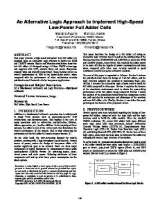
4.2 Weights Distribution Analysis of IRL Cars The application described in this section is an automatic system that allows the designer to automatically compute and evaluate mass properties of Indy Racing League (IRL) cars. During the design process, car components are sized in order to optimise the weight/strength balance with respect to the overall constraints imposed by the IRL technical specifications. Car mass distribution is then derived from the dimensioning of the car sub− assemblies. However, mass distribution is a fundamental parameter, which must be taken into account during design because of its contribution to car performance. The designer tries to improve car performance starting from the idea of a new car configuration. In this stage, the designer is guided by the perspective of achieving some particular advantages that s/he can foresee relying on personal expertise. Possible alternative solutions are evaluated in order to define the strategy of the following steps. A detailed analysis of the solution selected allows the designer to evaluate his/her original idea, giving a feedback of results on the hypothesis The developed application is based on a car model made by a set of features organised into a product model structure containing all car sub−systems (e.g., suspension and chassis). Different part−subpart relationships define the tree model and link an object (e.g., suspension) to its components (e.g., wishbones and wheel). Starting from a set of predefined independent parameters (design variables), the system automatically generates the car model configuration, including geometric models used to evaluate all properties related to derived dimension, position, mass, etc. During a typical working session, the user interacts with the graphic user interface (see Fig. 2) to edit independent design parameters and generate alternative car configurations. The user evaluates different car configurations by looking at the system outputs, which consist in numeric data (mass, centre of mass of both the car and its sub−systems) and graphic elements (car and sub−systems 3D representation). 7
The application has been developed in collaboration with Dallara (Italian leading company in the production of racing cars) using the Selling Point development shell by Oracle Corporation (Susca 1999). Main Window Graphic Area
Back System Window Toolbar
Tree Structure
Assembly Weight Parameters
Message Bar
Figure 2. User Interface of the Weights Distribution Analysis System
4.3 Cupboard Configuration The application described in this section is an automatic system for cupboard configuration that drives the user to the definition of valid configurations and automatically generates bills of materials, NC programs and offers for sale. Furniture configuration is traditionally performed by selecting and composing standard components (wall, shelf, back, drawer, door, etc.) from a catalogue. Due to assembly and manufacturing constraints, only a subset of all the possible configurations is allowed. The control about the validity of a configuration is usually left to the experience of the expert, usually sales assistant. If a configuration error occurs during the selling, this is usually detected during the assembly of the furniture. The error produces the need to reconsider the configuration and then to make corrections on the bill of material, with a consequent changes on the final price. This situation will delay the delivery and the final assembly of the furniture and will cause the customer disappointment. The risk to make a mistake during the configuration process rises when the customer asks for the modifications of standard components in order to meet constraints imposed by the furniture location (room dimensions, steps on the floor, etc.). The developed application is based on a cupboard model made by a set of features organised in two main subparts representing the internal and external components of the cupboard. The external part of the cupboard has a predictable structure made by a sequence of aggregated components and then it can be automatically generated starting from a set of independent parameters, such as the number of cupboard aggregates and the dimensions of each aggregate (see Fig. 3). 8
Armadio Parete
Terminale
Struttura Centrale
Vano
Base
Schienale
Parete
Angolare
Spalla
Struttura Centrale
Struttura Centrale
Spalla
Anta
Coperchio
Figure 3. Model Structure of the Cupboard Exterior
Conversely, the cupboard interior is dressed by interactively selecting a variable number and type of components that can be assembled on the basis of specific assembly constraints. In order to manage this situation, the subpart structure representing the cupboard interior has been enriched with a logical feature (called bay) that simulates the internal available space. The bay feature behaves as follows: when a new component is candidate to be inserted in the space available in the interior model structure, the bay feature checks the compatibility between the selected component and the selected location. This can be done thanks to the knowledge the bay feature has about the type of components surrounding the available space and the assembly constraints. Once the selected component has been verified and accepted, it is inserted in the interior model structure together with two new bay features, resulting from the split of the original one (see Fig. 4). Vano Vano
Ripiano Vano Estrattore
Vano Spalla
Vano Servetto
Figure 4. Model Structure of the Cupboard Interior
During a typical working session, the user first interacts with the graphic user interface to generate the cupboard external structure by providing independent parameters, such as number and dimensions of the cupboard aggregates (see Fig. 5 left). Then s/he starts to dress the cupboard interior by selecting internal components (see Fig. 5 right). Once the configuration process is completed, the user can ask the system to automatically generate bill of material, NC programs for the components that requires additional manufacturing, and sale offer. The application has been developed in collaboration with Molteni (Italian leading company in the production of furniture) using the Concept Modeller development shell by Wisdom Systems (Mandorli 1995).
9
Figure 5. User Interface of the Cupboard Configuration System (for exterior and interior definition)
5.
CONCLUSIONS
The paper describes three different applications developed with the support of KAE technology. Several distinctions can be noticed among these applications, regarding geometric aspects, product structure, product definition and evaluation process. In particular, for the wires application the geometry representation required to support the evaluation process is mainly 2D (automatic generation, representation and positioning on a plane of a huge number of wires), while both for racing car and cupboard application it is 3D. The IRL car application 10
requires the evaluation of mass and centre of mass properties of the car 3D model, the cupboard application requires reasoning about the adjacency relationships and the dimensions of the 3D objects that build−up the cupboard model. Regarding the product structure and structure definition process, the product model for the racing car application is purely generative (the car structure is automatically generated by the system on the basis of user inputs), while the wire and the cupboard applications require an hybrid approach where a part of the product model is automatically generated and another part is interactively defined by the user: the truck cabling for the wire application and the interior definition for the cupboard application. Nevertheless, a significant common point can be identified among all of the three developed applications: the design process is known and stable and the product structure is predictable. This is the premise for a successful application of KAE technology that is based on the exact identification of the design process for a particular product family and on its organisation into a prototype, which is characterised, by the same rules and procedures that are traditionally used by the designer during her/his activity. The most critical issue of a KAE application is the analysis of the design/manufacturing process, that must lead to the identification of the independent design parameters (later used to generate alternative design solutions), the constraints each solution must satisfy, and the criteria that will support, or automatically perform, the evaluation of the generated solutions. The correct analysis of the design problem and its mapping into an appropriate product model can lead to the development of a system able to perform all the repetitive tasks of the design process and to automatically verify/ensure that generated solutions are acceptable, saving a lot of the designer’s time. A significant side−effect of the development of a KAE application is that the implemented product model serves as a centralised repository for engineering information and expertise, that can be eventually re−used for education/training of junior engineers.
ACKNOWLEDGMENTS This work is dedicated to our friend Lorenzo.
REFERENCES Bidarra, R., and Bronsvoort, W. F., (2000), Semantic Feature Modelling, Computer−Aided Design, Elsevier Science Ltd., N. 32, pp. 201 − 225. Cross, N. (1998). Expertise in Engineering Design. Research in Engineering Design, Vol. 10, pp. 141 − 149. Di Lecce, B., Tagliabo’, F., Mandorli, F., Accornero, B., and Strata, A. (1997), A Knowledge−Based tool for automatic generation of wire harness design and schematics, in Proceedings of 6th European Conference, Lightweight and Small Cars, the Answer to Future Needs, Vol. 2, pp. 987 − 998. Gao, S., Chen, Z., and Peng, Q., (2000), Feature Validity Maintaining Based−on Local Feature Recognition, In CD−ROM Proceedings of the 2000 ASME International Computers and Information in Engineering Conference, ASME. Mandorli, F., (1995), Sistemi per lo sviluppo di applicazioni KAE: un esempio nel settore degli armadi componibili, In IX Convegno Nazionale Associazione Nazionale Disegno di Macchine (ADM ’95), pp. 171− 180.
11
Mandorli, F., Cugini, U., Otto, H.E., and Kimura, F., (1997). Modeling with self Validation Features, in Proceedings of ACM/IEEE Symposium on Solid Modeling and Applications ’97, pp. 88−96. Moulianitis, V. C., Dentsoras, & A.J., Aspragathos, N.A. (1999). A Knowledge−Based System for the Conceptual Design of Grippers for Handling Fabrics. Artificial Intelligence for Engineering Design, Analysis and Manufacturing (AIEDAM), Vol. 13, No. 1, pp. 13−27. Ognjnovic (1996). Decisions in Gear Train Transmission Design. Research in Engineering Design,Vol. 8,pp. 178 − 187. Rosenfeld, L.W., (1995), Solid Modeling and Knowledge−Based Engineering, Handbook of Solid Modeling, Eds. Donald E. LaCourse, McGraw−Hill Inc. Shah J.J. and Mäntylä, M. (1995), Parametric and Feature−Based CAD/CAM: Concepts, Techniques, Applications, John Wiley & Sons, New York, NY. Shah, J.J., Mäntylä, M. and Nau, D. (1994), Introduction to Feature Based Manufacturing, Advances in feature based manufacturing, Elsevier Science B.V. Susca, L., Mandorli, F., Rizzi, C., and Cugini, U. (2000), A Racing car design using knowledge aided engineering, Artificial Intelligence for Engineering Design, Analysis and Manufacturing (AIEDAM), Vol. 14, No. 3, pp. 235 − 249. Vernadat F.B. (1996). Enterprise Modeling And Integration − Principles and Applications. Chapman and Hall.
12