tooCool(boolean,[param(float(t))]), turnOn(boolean,[ ])]). The dynamic part of the thermostat system model is declaratively written as follows. state diag(thermostat ...
Electronic Notes in Theoretical Computer Science 95 (2004) 111–129 www.elsevier.com/locate/entcs
VeriAgent: an Approach to Integrating UML and Formal Verification Tools 1 E. Motaa , E. Clarkeb, A. Groceb , W. Oliveiraa, M. Falc˜aoa and J. Kandaa a Universidade Federal do Amazonas, Departamento de Ciˆ encia da Computa¸c˜ ao, Av. Gen. Rodrigo Oct´ avio Jord˜ ao Ramos, 3000 – 69077-000 Manaus, AM 2 b
Carnegie Mellon University, Computer Science Department, 5000 Forbes Avenue, Pittsburgh PA 15213-3891 3
Abstract The mathematical notations of Formal Verification Tools (FVTs) do not prevent us from wrongly defining the behavior of systems, any more than modern CASE tools do. With software rapidly growing in size and complexity, graphical specifications in languages like UML need to be formally verified, before the implementation phase, in order to guarantee the development of more reliable systems. While the enterprise of integrating CASE and FVTs has had reasonable success with the translation of simple diagrams to model checkers’ notations, there has been few progress regarding the fundamental aspects an interface should have to fully integrate them. In this work we present an interface for joining both technologies as a reliable solution to bridging this gap. Keywords: Verification Tool, Verification Agent, Transformation.
1
Introduction
The mathematical notations of formal verification tools do not prevent us from wrongly defining the behavior of systems, any more than UML-based 1 2 3
Work partially supported by CNPq/MCT-EsVIA Project, grant 550730/01-0. mailto:{edjard,woliveira,marcia,jkanda}@ufam.edu.br mailto:{emc,agroce}@cs.cmu.edu
1571-0661 © 2004 Published by Elsevier B.V. Open access under CC BY-NC-ND license. doi:10.1016/j.entcs.2004.04.008
112
E. Mota et al. / Electronic Notes in Theoretical Computer Science 95 (2004) 111–129
CASE tools do. 4 However, the languages used to build models in the former have precise semantics which allow us to find errors by means of automatic verification algorithms, e.g. model checking, which is not the case in the latter. CASE tools are considered to be user-friendly because of their graphical representation and their “capability” to provide free textual information to describe constraints not captured either by diagrams or constraint languages (for instance OCL). Thus, CASE tools lack the necessary apparatus to perform (semi-)automatic processing over models. With software rapidly growing in size and complexity, graphical specifications in languages like UML need to be formally verified, before the implementation phase, in order to guarantee the development of more reliable systems. A few years ago, the formal verification community began investigating mechanisms to integrate such graphical specifications with verification tools. While this approach achieved reasonable success on the translation of simple diagrams to model checkers’ input notations, the results of verification were not well integrated back into the CASE tools’ process. Interpreting the results of verification is still highly human-dependent, and the intensive use of these tools in software development is yet to be achieved. We claim that a protocol interface joining both technologies can be a more reliable solution to bridging this gap. First, it would avoid the introduction of further notational overhead on either side. Second, we would be able to implement algorithms for reasoning about the relationships between high level specifications and verification results. Finally, such a protocol could also be used for guiding the verification result’s explanation with an AI agent “flavor”. This way of bridging the gap allows a convenient marriage between the operations that map to models on both sides. This representation allows a “pre-processing” of system development models in such a way that when they are translated into formal specifications we can retain their original semantics. This means that the results of verification can be better mapped into causal explanations on the model. The rest of this paper is organized as follows. In Section 2 we outline the fundamental ideas that motivated our research, and also the features a protocol interface should have in terms of language for intermediate representation and functionalities. Section 3 presents an implementation of such a protocol at the representation level. Section 4 describes an experimental result of an actual implementation of our approach for SMV translation, and and make a brief analysis pointing out the way to turn back the verification result in 4
In this text we use the term CASE to mean the modern Computer Aided Software Engineering tools based on UML graphical notation, although it originally was used to describe tools to support the development of structured programming methods
E. Mota et al. / Electronic Notes in Theoretical Computer Science 95 (2004) 111–129
113
terms of error analysis. In Section 5 we describe our efforts in relation to other research in this area. Finally, in Section 6 we address some remaining open questions.
2
An AI Perspective for Integration
In this section we present the motivation of this work and the Artificial Intelligence (AI) perspective to integrating Formal Methods (FMs) and UML tools for system development. 2.1 The Reasons for an “Intelligent” Intermediate Level One of the main purposes of Software Engineering (SE) is to enable developers to build systems that operate reliably despite their complexity. The formal methods community has developed many tools to help achieve this goal. The mathematical nature of such tools has not contributed to their adoption in the daily activity of software development. This may be because, in the past, software applications did not require rigorous definitions, as they were mostly focused on information systems. In order to handle complex information CASE tools were developed, and they evolved to the point of being semi-formal as is the case with many object-oriented tools such as those based on the Unified Modeling Language (UML). UML CASE tools provide functionality for obtaining better abstraction with encapsulation capabilities, and offer a variety of mechanisms for defining the structure and behavior of systems. These mechanisms are not, however, sufficient for precise analysis as required for new market demands with respect to reliability. Such tools could aid in the development of safety critical systems if they were combined with formal methods to achieve this precision. According to Clarke et al. [3], in order to join these approaches in an attractive way some fundamental concepts should be developed and new tools should satisfy some criteria. These criteria are not necessarily related to formal methods. The current state of CASE technology does not embody three of these criteria, namely composition: the combination of methods, specifications, models, theories, and proofs. abstraction: the identification of levels of abstraction (possibly), taking the features of application domains into account. reuse of models and theories: the use of parameterized models and theories, avoiding the need to start from scratch each time a new application is tackled.
114
E. Mota et al. / Electronic Notes in Theoretical Computer Science 95 (2004) 111–129
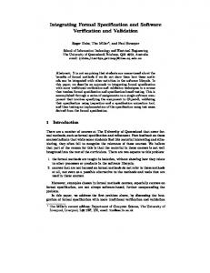
One might argue that these concepts are used in some way at both the semi-formal specification and formal verification levels. Unfortunately, the notations and therefore the embodiments of the concepts are very different. Even worse, if the notations do “match” it does not imply the combination is correct, as Clarke also pointed out [3]. Scientific advances and technological developments in both areas have reached a point that trying to embody the features of one (FMs) into another (CASE tools), would be similar to building an “all purpose development tool.” In order to join these disparate worlds it is necessary to introduce, on each side, translation mechanisms and interpretation methods in order to deal with the feedback from verification tools. This can be problematic for the following (not exhaustive) reasons. (i) UML itself is a miscellany of graphical language notations, and it seems unproductive to make a verification tool support all diagrams. However, if any one is chosen, there could be application domains where the others would be more relevant. (ii) Direct mapping of UML diagrams into a formal notation may bring semantical correspondence problems (depicted in Figure 1), such as: • the loss of the original UML model at the verification level • the difficulty to mapping back the result of verification onto the original model. S3
S1
Semantical Correspondence?
S4 S2
S5
S6
MODULE main VAR state : {S1,S2,S3} ... AG(state=s1 −> EF (state = s6)) MODULE S3(e) VAR state : {S$,S5,S6} next(state) = case state=s1 : {s3,s2} esac ...
Fig. 1. Problems with semantical correspondence between UML and formal notation.
(iii) Large scale software development deals with huge flows of information across model diagrams, team notes, etc. To manually map all of this to a verification model would be unproductive, as the time a product has to reach the market is small compared to the time necessary for training dozens of developers in using formal verification tools. A single solution to all of these problems seems to be a nearly impossible target. The concepts associated with their union, however, point to the crystallization of a computational entity suitable to mediate the integration of both CASE and formal verification tools. The concept of a protocol has allowed better management of huge flows of information across computer net-
E. Mota et al. / Electronic Notes in Theoretical Computer Science 95 (2004) 111–129
115
works and the Internet. In the same way, an interface (or protocol) layer between CASE and formal verifications tools would be more likely to succeed in scaling than either one alone. The methodology we used to analyse the requirements for such a layer is based on the concept of intelligent agent from Artificial Intelligence [17], and we claim it is justified for the following reasons. •
Automatic translation, alone, from models in UML to models for verification is useless without tools for managing this translation and applying it to handle complex systems. For instance, cause analysis of errors in such systems is still basically done by specialists with no automatic support at all.
•
There is lot of knowledge in between both worlds not associated to algorithmic verification or high level modeling per se. For example, synthesis is not meant to be only simple translation or cross-execution. It could also be used to search for a similar model (or parts of one), which has already been verified and simply give back previous verification results.
•
The “computational skill”, or in AI jargon reasoning mechanism, necessary to find common patterns between a new model of a system and old ones requires a representation approach able to capture common features using structural language elements as much general as possible. In this way, we may reify dynamic behaviour into “static relations” or snapshots of the system’s behaviour.
•
For very large systems the more a development tool is able to find out patterns previously verified, the stronger will be confidence in the composition of them.
These features are usually named as synthesis, compositional reasoning, and error explanation, and are all important aspects associated to verification presently lacking in automatic verification tools. The emphasis of our solution is that a layer to join both worlds must have some way of knowing, out of many possible interpretations (executions or inferences) of a model it could draw, which ones it should actually draw. In other words, which ones are rationally better (computationally less expensive) than others. 2.2 A First-Order Language Layer The first aspect of an interface protocol for data exchange is the language for representing the information it is supposed to process. As we are dealing with two different kinds of notation this common language must be as general as possible in terms of structural representation of information. First-Order
116
E. Mota et al. / Electronic Notes in Theoretical Computer Science 95 (2004) 111–129
Logic (FOL) is most suitable for the following reasons. •
FOL is “computationally universal” in that any problem with a computational solution can be described in it. Moreover, such descriptions can be reduced to Horn clauses for logic programs: a set of axioms and rules defining relationships among objects.
•
There are many efficient inference engines for handling first-order expressions or logic programs. These expressions are, by definition, well-structured elements allowing us to create abstractions to represent any computational model.
•
FOL can be used to fiber other logical representation languages [8], and so we may perform, among other tasks, synthesis across UML models and formal verification notation.
•
The strong relation between syntax and semantics of FOL representation may produce a side-effect on the discipline of using graphical tools. The reason is that while we may keep the original functionalities of a graphical tool, we may warn developers not to “abuse” the graphical freedom of design. Provided the discipline is followed, we should be able to better identify patterns of specification and their relations to patterns of verification models.
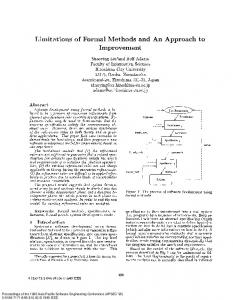
Another interesting advantage of using FOL is that the recent demands for model exchange across enterprise applications brought about the XML Metadata Interchange (XMI) [16]. Any valid XML description is associated to a Domain Object Model (DOM). As DOM descriptions are easily mapped into first-order expressions, all modern UML-based CASE tools which export to XMI can be used in our architecture (see Section 4 for an example). Figure 2 depicts the idea of the sort of integration we are proposing. We map a system model UML statechart represented, for example, in XMI, into its first-order representation [7]. A First-Order Specification Model (FOSM) representation can be used as a knowledge base for reasoning about structural properties of the model and consistency checking. Other applications are possible including synthesis (as depicted at the flat level of Figure 2). This is used, for example, in transforming a FOSM description into a First-Order Verification Model (FOVM) which represents the target verification notation, which is then easy to translate directly into the formal verification tool’s input notation. A FOVM is derived from a FOSM by means of transformation rules when requested. At first glance it might seem strange to T-encode computational models of verification methods when they offer suitable notation to represent reactive (embedded) systems, and also T-encode inference mechanisms
E. Mota et al. / Electronic Notes in Theoretical Computer Science 95 (2004) 111–129 S3
S1
S4 S2 S5
S6
117
MODULE main VAR state : {S1,S2,S3} ... AG(state=s1 −> EF (state = s6)) MODULE S3(e) VAR state : {S$,S5,S6} next(state) = case state=s1 : {s3,s2} esac ...
XMI −> FOL First−Order Representation level
FOSM
state_diag(c, [s1], [flat(s1),flat(s2),flat(s3)], [trans(s1,...,s2), trans(s1,...,s3), ...]) state_diag(s3,[s4]...)
Synthesis
module(id(main), var([scalar(state,[s1,s2,s3]), instance(s3_child,module(id(S3), [e]))]), [... assign(next(state),case( ..)])
FOVM
Fig. 2. The interface layer to join UML tools and formal verification.
for proving properties about them. In most of these problems a finite state machine (FSM) 5 is sufficient to represent the system behavior. Along with FOSM and FOVM, the reprerentation level should also have ways of representing the results of verification in first-order notation. This information we call First-Order Verification Result (FOVR). To this triple we name pattern of verification. Our proposition is that a VeriAgent needs a representation for patterns of verification in order to perform meta-reasoning about problem descriptions and represent knowledge about verification. These patterns need not be represented in the original computational model notation of formal methods. 2.3 The Inferences or Functionalities Layer This layer is an open set of reasoning mechanisms to actually manipulate FOSM, FOVM and FOVR. Such mechanisms or functionalities are not directly associated with formal verification methods. It is open because we allow the introduction of new mechanisms to extend the functionalities of a VeriAgent. Some of these functionalities have been developed in the last ten years or so, and others have never been realized. Our non-exhaustive list includes: Synthesis to transform XMI notation into FOSM, and also to map (reduce, compose, fiber, etc.) first-order representations into one another. Property extraction to generate interesting properties, candidates for verification, as logical formulas. Formal Code Generation to allow the translation of FOSM notation into formal language notation. For instance, NuSMV for Model Checking. Choice of tools to allow developers and experts to pick a suitable verification tool given a new system specification model. This task certainly needs 5
FSM or one of its well known extensions, e.g.Fair Transition Systems [14].
118
E. Mota et al. / Electronic Notes in Theoretical Computer Science 95 (2004) 111–129
to interact with synthesis. Verification Results to reason about patterns of specification and their relation to patterns of verification associated with the history of solutions to errors previously found. Error Explanation to choose the appropriate means for explaining the errors found, and to aid in debugging the model and specification. Compositional Reasoning to exploit the organization of systems as interacting components and to isolate components already verified from those with potential errors. Historical Reasoning to keep track of which aspects of system development have been formalized and verified. This is actually the third layer to store patterns of reasoning about the verification of certain models (possibly associated with specific application domains). This knowledge base depends on the first-order representation. To carry out the tasks listed above we propose a Verification Agent (VeriAgent henceforth) as a computational component used to combine Formal Methods and modern modeling languages, e.g. UML. This agent is composed of three layers or components as depicted in Figure 3. The system’s developer interacts with the Graphical Services interface, for example UML. After defining a new model she/he aks the VeriAgent to check for systems’ correctness. The model is then translated into a FOSM representation, and the user is requested to choose, from a list of generated properties, some he/she wants to check. The agent may perform synthesis and generate a FOVM model. The agent searches for a pattern of system’s verification that matches these two models, by using some kind of semantical unification as done in [15] for temporal reasoning. If some some is found, then the agent simply retrieves it and give back to the developer the corresponding FOVR, otherwise it breakes the original model and apply the same procedure to each submodel. If it fails then it will call the verification tool passing as arguments the property and the FOVM submodels into the appropriate notation for the chosen tool. The module named Verification Guide is not in the core of the VeriAgent, because it is a kind of interface which can be present in any of the approaches listed in the figure. This module presents the outcomes of the reasoning module (mainly for error explanation and causal analysis) to the developer in a suitably helpful way. This can often probably be accomplished by extending the graphical tool interface with the necessary features for that purpose.
E. Mota et al. / Electronic Notes in Theoretical Computer Science 95 (2004) 111–129
Graphical Services UML Model
First Order Representation
FOSM
119
Verification Tools FOVR
SMV
FOVM
BMC Reasoning Mechanisms
Verification Guide
Diagram Natural Language etc.
Synthesis, Semantical Unification, Compositional, Historical Reasoming Error Explanation, Causal Reasoning History of Verification
Patterns of Verification "Knowledge" about Compositional Reasoning
JPF
SPIN
etc.
Fig. 3. The VeriAgent architecture.
3
A VeriAgent Implementation
3.1 LogUML: a FOSM Based on Logic Programming The purpose of FORL is not to execute a FOSM, FOVM or FOVR in standard computational logic fashion, but rather to use well known logical inference engines to reason about patterns of both worlds and also about the results of verification. Thus, this layer is composed of three model theories represented as sets of well-formed structured expressions in first-order logic (FOL). At this level we use the T-encode Hilbert style of representation [18] to deal with those relations that, in their original computational model, would represent relations, concurrent processes, etc. In our case we are dealing with UML diagrams—in this work just statecharts. The logical form we use as an example is a subset of the Logic Programming (LP) [13] language. Apart from having a strong relation between syntax and semantics, LP has a powerful meta-language mechanism for prototyping of any other notation we want to propose or extend LP itself. We shall use Prolog despite the fact that it is based on standard first order logic language, and so we have no structure for representing concurrency in a suitable way. However, we are still able to map “states of concurrency” into structured terms of our object language notation. This means that relations or even processes specification can be reified into terms. For the purpose of this paper we shall concentrate only on the representational aspects of UML statecharts and its counterpart in a formal verification framework. For lack of space, not all of these concepts will be shown here in this work. In what follows we define a Logic for Unifying Modeling Language,
120
E. Mota et al. / Electronic Notes in Theoretical Computer Science 95 (2004) 111–129
or simply LogUML. 3.2 Vocabulary The idea is basically to extend the usual set of symbols as follows. variables Lv is extended with the finite set Vuml of LogUML variables. constants Lc is extended with the finite sets Cuml for names of classes, Snames for names of states, Dnames ⊆ (Cuml ∪ Snames ) for names of diagrams, and S= , S� = , SA , S� A for flat, super flat, advanced and superadvanced states, respectively. Npar for names of parameters, and Natt for attributes names, Noper for names of operations and Nτ for names of valid LogUML set types. Euml is a finite set of special functions for representing elements of the LogUML language. For the purpose of this work we shall consider the following subset of it: {operations/1, param/1, attributes/1, f lat/1, super/1} ∪ Aadv ∪ Tuml ∪ Pτ , where • Aadv is a set of functions, each one corresponding to an activity for UML advanced states, • Tuml is the set {trans/5, event/1,cond/1, action/1} • Pτ is the set of unary function-types {t1 (x1 ), . . . , tn (xn )}, and each xi ∈ Npar ∪ Natt , and ti ∈ Nτ . We add the special predicates class/3 and state diag/4 into the set of predicates LP . Logical Symbols are the usual ones in standard Logic Programming. 3.3 Classes of Expressions The classes of expressions we want to represent should reflect the elements of an UML specification into the elements of LogUML language. For this work the definition of a LogUML description of a system constitutes the specification of its structure and of its behaviour. A structure of a class represents its interface with the environment and so it should embody the class name, its attributes and operations. The behavior is captured through a diagram which embodies states and transitions. In what follows we shall formalize these concepts and get into a more detailed definition of each one. attribute is a term of the form attrib(X) and X ∈ Pτ parameter is a term of the form param(X) and X ∈ Pτ operation is set of terms in the form ti (T, P ars), where ti ∈ Noper , T ∈ Pτ ,
E. Mota et al. / Electronic Notes in Theoretical Computer Science 95 (2004) 111–129
121
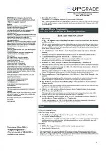
and P ars ⊆ Npar ; state is an element of the set Ds = S= ∪ S� = ∪ SA ∪ S� A , where elements of S= are of the form f lat(s), S� = are of the form superf lat(s), SA are of the form advanced(s, la), S� A are of the form superadvanced(s, la), and s ∈ Snames , and la ⊆ Aadv . transition is a term of the form trans(s1 , event(E), cond(C), action(A), s2 ), where s1 , s2 ∈ S, E is a list of events, C is a “boolean condition” and A is a list of actions. Actions can have conditions to be activated, for which we use T-encode [18], to encode the implication (X → Y) with the function impl(X, Y ). class is an association of a class name C, attributes A and operations O, written class(C, attributes(A), operations(O)). state diagram is an association of Diagram name, a set of initial states, a set of states, and a set of transitions, written as state diag(D, Is, S, T ), where D ∈ Dnames , Is ⊂ Snames , S ⊆ Ds , T ⊆ Tuml LogUML class is a term of the form class(C, A, O), where C is the name of the class, A is a set of attributes and O is a set of operations. 3.4 An Example of Mapping UML into LogUML Figure 4 shows a simple UML model for a thermostat. This model was defined using the ArgoUML 6 tool which exports diagrams to XMI by using a plugin added into ArgoUML called PLogAr, generating a LogUML code. tooCool(t)
Heating
Idle
atTemp(t)
shutDown tooHot(t)
activating
atTemp(t)
[ready]/turnon
tooCool(t)
Cooling tooHot(t)
active
Fig. 4. Thermostat Statechart Model
The translation from UML statechart into LogUML is not so difficult and 6 ArgoUML is a Copyright of Tigris Open Source Community which promotes Open Source Software Engineering.
122
E. Mota et al. / Electronic Notes in Theoretical Computer Science 95 (2004) 111–129
for this example is actually very simple, since we have defined the UML elements as recursive first-order terms with a finite computation on the translation. This example above is written in LogUML as follows. For the static pat of the model we shall interpret the thermostat as a single unbreakable class, but it could be different. So we have the following class model definition. class(thermostat, attributes([f loat(t)]), operations[ready(boolean,[ ]), shutDown(boolean,[ ]), atT emp(boolean, [param(f loat(t))]), tooHot(boolean, [param(f loat(t))]), tooCool(boolean, [param(f loat(t))]), turnOn(boolean,[ ])]). The dynamic part of the thermostat system model is declaratively written as follows. state diag(thermostat, initialstates([idle]), [f lat(idle), f lat(cooling), superf lat(heating)], [trans(initial, event( ), cond( ), action( ), idle), trans(idle, event(shutDown), cond( ), action( ), f inal), trans(idle, event(tooHot), cond( ), action( ), cooling), trans(idle, event(tooCool), cond( ), action( ), heating), trans(cooling, event(tooCool), cond( ), action( ), heating), trans(cooling, event(atT emp), cond( ), action( ), idle), trans(heating, event(tooHot), cond( ), action( ), cooling), trans(heating, event(atT emp), cond( ), action( ), idle)]). state diag(heating, initialstates([activating]), [f lat(activating), f lat(active)], [trans(activating, event(ready), cond( ), action(turnOn), active), trans(initial, event(tooCool), cond( ), action( ), activating)]).
E. Mota et al. / Electronic Notes in Theoretical Computer Science 95 (2004) 111–129
4
123
Mapping UML to SMV
In this section we describe the experimental result of an actual implementation of a VeriAgent tool. A detailed description of the tool, using ArgoUML is available [7]. The purpose here is to present part of the behaviour of an implementation of VeriAgent. Note that during the translation from XMI to LogUML the pseudo-states initial and final, are introduced for completeness reasons. This notation does not need to be shown to the developer as it is used as intermediate data for other purposes (see Section 3). Synthesis is called within the ArgoUML environment, and is performed by a Logic Program which implements the translation chosen by the modeler. Such translations are seen, from the VeriAgent perspective, as first-order interpretations. Here, we map UML to Nu-SMV’s input notation using the following translation assumption. 4.1 An SMV Interpretation of UML Statecharts From the (object-oriented) programming level perspective, event, action and condition have the same semantics, i.e. they are just methods. What each one does and returns as a result will differentiate one from another. As there is no meaning for a transition with only a (guard) condition [5] and no event associated we do not consider that case. Thus we simply add scalar variables to each state to represent the states of the statechart. Due to space restrictions this paper only considers events and states. There is also one type of module variable (with possibly more than one instance). We shall use only ASSIGN expressions in SMV to represent the transitions to change these variables. This gives us the following, informal, mapping rule: Every statechart D represented by predicate state diag(D, I, S, T ), where S is the set {s1 ,. . . ,sk } of states, T is the set of transitions, and E is the set {e1 ,. . . ,en } of events which trigger transitions in T, is translated into MODULE D; VAR state : {s1 ,...,sk }; event : {e1 ,...,en }; si child : Si(event); INIT init(state) := initial init(event) := default ASSIGN next(event) := E; next(state):= next(state) := case ... state = si & e :
sj ; ...
124
E. Mota et al. / Electronic Notes in Theoretical Computer Science 95 (2004) 111–129
esac; MODULE Si(e); ... where every line of a next(state) case expression is associated with a transition trans(si , event(e), cond(c), action(a), sj ) in the state diagram. Note that here we ignore conditions and actions as explained above. Our mapping observes some basic principles. First, statecharts at level zero are mapped to “MODULE main”, and superstates are modules called by the module that it sees events rise from. In the translation schema above D can call main, and all its sub-machines are modules. The hierarchy is derived by simply creating a child variable in every module which has a superstate. 4.2 The Thermostat Example Using the rules established in the previous section the thermostat diagram is translated from LogUML into the following SMV code. First the main diagram is translated as the main module. Note that an abstraction is made for every super state and a child submodule is declared as a variable. MODULE main VAR state : {heating,cooling,idle,final,initial}; event : {default, atTemp, tooCool, tooHot, shutDown}; heating_child : Heating(event); ASSIGN init(state) := initial; init(event) := default; next(state) := case state = initial & event = default : idle; state = heating & event = tooHot : cooling; state = heating & event = atTemp : idle; state = cooling & event = tooCool : heating; state = cooling & event = atTemp : idle; state = idle & event = shutDown : final; state = idle & event = tooHot : cooling; state = idle & event = tooCool : heating; 1 : state; esac; next(event) := {default, atTemp, tooCool, tooHot, shutDown}; The recursive nature of the logical notation allow us to translate any subdiagram or super state as a separated module. The superstate heating of the thermostate becomes a module Heating, and the child variable of the main module is a type of Heating module.
E. Mota et al. / Electronic Notes in Theoretical Computer Science 95 (2004) 111–129
125
MODULE Heating(event) VAR state : {initial,active,activating}; ASSIGN init(state) := initial; next(state) := case state = initial & event = tooCool : activating; state = activating : active; 1 : state; esac; Note that we do not derive properties to be verified. In our tool the user still has to enter the Computational Tree Logic (CTL) formula or Linear Temporal Logic formula to be checked. Suppose we want to prove the following safety property “the thermostat will never stay in the active state when the temperature is too high.” This is represented in CTL as follows: SPEC AG ((state = heating & event = tooHot) -> AX (! heating_child.state = active)) Verification and Analysis After translating the original model into LogUML and then into SMV, we are able to model check the translation (which has the same name as the model with the extension “.smv”). We used the NuSMV [1] model checker and ran the verification as follows, where the option int runs an interactive mode of NuSMV, and the command check spec verify all specifications given: [mozart@smv-examples]nusmv -int thermostat2.smv *** This is NuSMV 2.1.2 (compiled 2002-11-22 12:00:00) NuSMV > go NuSMV > check_spec -- specification AG ((state = heating & event = tooHot) -> AX (!heating_child.state = active)) is false -- as demonstrated by the following execution sequence -> State 1.1 State 1.2 State 1.3 State 1.4