May 17, 2003 - Intrusion Detection Systems (IDS) have been developed to solve the problem of detecting the attacks on several network systems.
An Architectural Framework for Distributed Intrusion Detection using Smart Agents V. Chatzigiannakis, G. Androulidakis, M. Grammatikou, B. Maglaris Network Management & Optimal Design Lab (NETMODE), ECE Department – National Technical University of Athens (NTUA) 9 Iroon Polytechniou str. Zografou, Athens, Greece Tel.: +30 210 7721450 Fax: +30 210 7721452 {vhatzi, gandr, mary, maglaris}@netmode.ntua.gr Keywords:Distributed Intrusion Detection, Smart Agents, Central Management, Rate Limiting, IDMEF data model
Abstract Intrusion Detection Systems (IDS) have been developed to solve the problem of detecting the attacks on several network systems. In small-scale networks a single IDS is sufficient to detect attacks but this is inadequate in large-scale networks, where the number of packets across the network is enormous. In this paper, we present an Architectural Framework considering the large-scale network environment. We designed and implemented a Distributed Intrusion Detection system that relies on Smart Agents which monitor network traffic and report intrusion alerts to a central management node. Distribution is handled through the introduction of multiple sensors and the use of Smart Agents who are responsible for reporting and rate limiting of messages. Finally, we extended the IDMEF (Intrusion Detection Message Exchange Format) data model to support digital signatures and to strengthen the authentication of the system.
1. Introduction An Intrusion Detection System (IDS) has been traditionally categorized according to the way it collects data and the detection method used on the data collected [1]. If the data processed originates from one or more hosts, then the IDS is called host-based. This methodology is mostly based on examining system logs and has become obsolete. However, if the IDS monitors a network of interconnected hosts for malicious traffic it is called network-based. Networkbased intrusion detection systems are more efficient because of their ability to combine network traffic data with audit data from individual hosts. The second categorization divides IDS into anomaly detection and misuse detection systems. Anomaly detection systems monitor the system and try to decide whether its behavior is normal or not. This is achieved by keeping user group and host profiles.
Usually a group profile is determined by the kind of programs used, the current time and duration of the user session. A host profile is determined by checking resources such as cpu and memory usage, the number of processes and users logged in. Such systems have to be continuously updated and adapted to changes in system and host behavior. Misuse detection systems on the other hand search for known attack signatures. A signature is a trail of a known attack. For example, it may be a specific series of bits in the header of an IP packet. Such systems resemble in their function to anti-virus programs. A weakness of this architecture is that they have to be updated on day to day basis, by downloading new attack signatures. Besides these classic approaches to the problem of Intrusion detection, there exists one more category: the Distributed Intrusion Detection Systems. These systems have recently started to evolve, because of the expansion of large-scaled networks. Traffic monitoring in such networks has been usually done in the past by installing sensors on the border routers or by using software provided by the router, like Cisco Netflow [2]. Nowadays, this schema seems obsolete, because of the burst in network capacity. It is impossible for an IDS to monitor a gigabit link without experiencing packet loss, no matter the hardware used. So, instead of using one central IDS, one should install a distributed system of sensors spread in the network to be monitored. However distributed systems introduce new barriers to be surpassed. First, the various sensors must share a common protocol for communicating with each other. Second, their intercommunication has to be secure; the data sent to the administrator must not be compromised. Moreover, a large number of sensors drives to an inefficient management. An additional problem is the extra traffic produced in the network. This problem may become more intense in case of a denial of service attack towards one of the subnetworks monitored. The alert messages from the
sensors that detected the attack could be large enough to result in extra flooding of the network. Finally, another problem is the correct placement of the IDS. This is a matter of great consideration and depends on the network topology and special characteristics such as the number of routers and especially border routers, the bandwidth of the links connecting routers and switches and the number of hosts.
2. Architecture 2.1. Setting our goal The main goal in our design is the intrusion detection in large-scaled networks. To address the problems discussed previously, we propose the construction of a cooperation framework between Intrusion Detection Agents. We install one or more Agents in every LAN of the network with the capability of reporting detected security events to a central message collection system. Every system is installed on a designated host. If a system is attacked and disabled, another host takes its place. This scheme is efficient because of its ability to combine information from many sources. The management of this distributed system consists of one or more central IDS nodes.
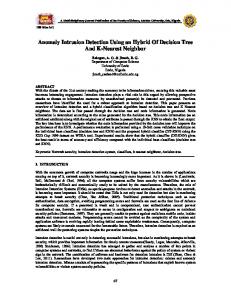
concerning network monitoring and simultaneously listens for new directions from the central IDS node. This is to be further analyzed in section 2.5. Figure 1 sketches the outline of the agent architecture we implemented. The Agent implementation consists of three tiers. In the lower tier, the Agent conducts network monitoring. This is done by a sensor which sniffs network traffic and searches for known signatures of attacks in IP packets. When a packet matches a known signature a signal is sent to the second tier. The second tier consists of a processor which buffers the description of the attack and decides whether an alert should be sent to the central node. This decision is based on the number of packets matched in a certain time threshold. This is very important because we achieve alert rate limiting. In case of a DoS attack the number of packets matched would be enormous. So, the lack of rate limiting of messages sent would result in a new DoS attack targeting the central node. The last tier is an output unit for the Agent. Its primary function is to transmit multicast alert messages defined by the previous level. The output unit also sends periodic messages reporting about the Agent’s state of operation.
2.3. System’s intercommunication
2.2. Agent Architecture Each node of our architectural framework is a smart Agent. The Agent performs a series of operations INTERNET
To Central IDS Node Router or Switch
Messages sent
Central IDS Node
LAN IDS Agent
OUTPUT IDS Agent
Messages to be sent (fragment of detected attacks)
AGENT
RATE LIMITER
LAN
IDS Agent
LAN
IDS Agent
LAN Router or Switch
LAN
Attacks detected LAN
NETWORK MONITOR
Packet sniffing
IDS Agent
DOS attack flow Multicast alert message
Figure 2. Network Architectural concept
Figure 1. Agent Implementation tiers
Figure 2 presents the system’s intercommunication which is achieved through multicast messages. There are two main reasons for choosing multicast. The first reason is that in the case of a denial of service attack on the network TCP traffic is almost impossible to pass through a flooded link. Consider a LAN experiencing a DoS attack. If the LAN’s intrusion detection system tried to communicate with the central node using TCP through the LAN’s upstream link, the connection would probably fail to be established. Although the packets transmitted by the IDS would reach their destination, the ACK packets would likely be dropped. The other reason for choosing such a schema is portability, ease of use and the possibility of using more than one central node for collecting messages. While the main node reports the site administrator about the security events detected by the various sensors, the secondary node passively and obscurely listens to the messages sent and is ready to take over in case of hardware failure or a DoS attack targeting the primary system. Moreover, it is desirable to use more than one IDS in every sub-network. This way we achieve load balancing in detection. The wide variety of known attacks usually results in a great load for a signature based IDS. To solve this problem, every system may focus in a narrow range of attacks so as be more efficient. The messages sent by the Agents to the central node are based on IDMEF (Intrusion Detection Message Exchange Format) [3]. It is a draft of the IETF working group which researches intrusion detection. IDMEF is an XML Document Type Definition for the exchange of messages between Intrusion Detection Systems. It supports two kinds of messages: Alerts and Heartbeats. Heartbeats are periodic messages. They mainly inform the central node that the system sending the message is operational. Besides that, they carry general information about the Agent. Alerts carry information about detected attacks.
2.4. Rate limiting The Agent stores each security alert A for a defined period of time TA. For every different case of attack, that is, source IP and port(s), target IP and port(s) and known signature, the Agent uses a unique alert identification. If λ is the number of alerts of type A sent from the first to the second level, the receive rate in the second level is:
rec A = λ TA
(1)
m = n rec A (2), then µ = ⎡λ m ⎤ (3) is the
So if
number of messages to be sent at the end of the timeslot TA. Rate limiting is achieved independently for different kinds of attacks. The transmit rate tranA is a fragment of the receive rate recA, as shown in the formula below.
tran A =
1 ⋅ rec A m
(4)
Figure 3 below shows the decrease in network traffic and presents the ratio λ/µ which is dynamic and depends on the denominator. Rate Lim it diagram for n=2 40
30
µ
20
10
0 0
10
20
λ
30
40 w ithout rate limit w ith rate limit
Figure 3. Rate Limit Diagram
2.5. Central IDS node The central IDS node does not monitor the network like the other nodes. Its purpose of existence is the control and fine tuning of the Agents, the gathering and storage of messages, and the notification of the administrator when necessary. The central IDS node acts like a manager for the Agents. This is done via a Graphical User Interface (GUI) that displays the graph of nodes. Each node represents an Agent and reveals the state of its operation. Through this GUI one can check the alert messages produced in every node, keep the system updated by downloading new known signatures and manage the policy of the message transmission rate
limiting. The latter is done by setting the duration of timeslots T and the parameter n of formula (2). What is critical for the optimal operation of our distributed system is the correct placement of the one or more central IDS nodes in the network. As shown in Figure 2 they should be installed as near the border router(s) as possible.
2.6. Security considerations Sending multicast messages introduces three main security flaws. First, the central node has to be certain that the sender of the message is really the one who claims to be in the IDMEF message. Second, the message received may pass through an insecure link, so we have to rest sure that it is not altered. Finally, the last problem to be addressed is the possible replication of the message by an eavesdropper. In order to solve these problems we should use secure multicast, but the solutions that they have been proposed in this area until now are not mature. Instead, we used public key cryptography embedded in the IDMEF messages. We propose an extended IDMEF DTD which includes a digital signature of the message. This way the receiver can verify the integrity and authentication of the message by using the public key of the sender, stored in its database. The threat of replicated messages is solved by the timestamp carried in a special tag of the IDMEF DTD called “Creation time”. Multiple alerts that have the same creation time are rejected.
3. Implementation 3.1. Agent Implementation We implemented the Agent in two different programs. The first is the daemon that listens for new instructions from the central IDS node. Communication between the latter and the Agents is done via secure TCP connections (SSL). Snort [4] has been chosen as the IDS sensor’s software for our system. Snort is a libpcap-based [5] software that can be used as a sniffer, packet logger or network intrusion detection system. In our case, we used Snort as a network intrusion detection tool. Snort belongs to the category of misuse intrusion detection systems. The detection of malicious packets is based on known attack signatures. Snort is able to detect a plenty of attacks such as DoS/DDoS attacks, Portscans, HTTP, DNS, SMTP, IMAP, POP3 attacks and Virus/Worm attacks. The alert mechanism of Snort has various ways of reporting detected attacks such as
in a user specified alert file, in another process using Unix Domain Sockets, sending notification in network management stations with the use of SNMP traps, even with winpopup messages in Microsoft Windows Workstations using samba. A new output plug-in has been constructed for Snort which is capable of using the IDMEF data model to send alerts from the sensor to the central IDS nodes. This plug-in limits the rate of alert messages before sending them. ruletype send-idmef { type alert output alert_fast: /var/log/snort/alert output alert_idmef: address=224.0.0.9 port=6789 ttl=1 analyzerid=sensor1 key=/home/gandr/snort/keys/key.pem dtd=/home/gandr/snort/idmef-message.dtd interval=300 T=5000 n=2 }
Figure 4. Our rule type A new rule type, called “send-idmef”, has been created in the Snort configuration file. The exact actions that take place when a rule of such type is triggered are shown in Figure 4. Firstly, we enable the fast alert output plug-in which writes a single line with the alert information in a local file. Secondly, we enable the new output plug-in, so that the alert message is sent to the central IDS nodes using IP multicast. There are nine parameters for the IDS sensor configuration in order to setup this plug-in in the Snort: (1) the IP multicast address to which the message is going to be sent, (2) the IP multicast port, (3) the value of the Time-To-Live field of the IP header which depends on the distance of the IDS sensor from the central IDS nodes, (4) the name by which the sensor will be known in the Distributed Intrusion Detection System, (5) the private key of the sensor that will be used to sign the IDMEF messages, (6) the XML Document Type Definition (DTD) of the IDMEF data model that will be used to validate the XML messages the sensor produces, (7) the interval (measured in sec) between the transmission of the Heartbeat messages, (8) the time interval T (measured in msec) between the transmission of Alert messages and (9) finally the parameter n of formula (2) which defines the rate of message transmission limiting. The plug-in constructs a linked list of alerts during the timeslot T. The linked list is empty at the beginning of every timeslot and gets populated with the arrival of new alerts. Every node of this list describes an alert type and contains these attributes: alert id, source IP and port(s), target IP and port(s), signature and number of iteration. For every new type of alert a new node is
constructed. If this type of alert already exists in the list, then the iteration number is increased by one. At the end of the timeslot, formula (3) is applied on the number of iterations λ. The result µ is the number of messages to be sent. After all that, the list is destroyed and the system enters the new timeslot. For the implementation of the IDMEF messages, both for the Alert and Heartbeat, we used the libidmef library [6], which is based in libxml2 library [7]. Analyzer, Source, Target, CreateTime and Classification information of the attack are the elements that constitute the Alert type IDMEF message. For the construction of the Heartbeat message, which is used to inform the central IDS nodes that the particular IDS sensor is working properly, the plug-in creates a new process. This process is responsible for monitoring the state of the Snort process. It checks periodically if the Snort process is running normally and if so, it sends a Heartbeat message to the central IDS nodes. If either process dies, then so does the other, leading to the termination of the Heartbeat message transmission. As we mentioned before, in order to prevent central IDS nodes from receiving forged IDMEF messages, we extended the IDMEF data model to support digital signatures. For each IDMEF message, a digital signature is produced. Both the IDMEF message and its signature are wrapped in a new single SignedIDMEF message which is sent to the central IDS nodes. The signature is implemented using the MD5 algorithm [8] to produce the digest of the IDMEF message and the RSA algorithm [9] to encrypt the message digest with the use of the private RSA key. For the key pair generation we used the openssl [10] command line utility. We created one pair of RSA keys for each IDS sensor to ensure that in the case a sensor gets compromised, we could still trust the signed messages coming from the other sensors. Each private key is stored in a particular IDS sensor, while all public keys are stored in the central IDS nodes.
3.2. Central IDS node implementation Each central IDS node is equipped with an application similar to HP Openview [11], written in Java language. This application is responsible for receiving signed IDMEF messages, verifying their signature and storing the information they contain in a database. Moreover, through secure TCP connection one can manage the Agents. The application protocol used is proprietary and is still under consideration.
eleni.netmode.ece.ntua.gr 147.102.13.11 2003-05-17T12:39:08Z 219.94.88.197 1264 147.102.13.1 23 SCAN SYN FIN http://www.whitehats.com/info/IDS198 509c9cbbd0a321d30040e2b47133d5d2ea8060ba821 85b43656399aa4fa2cf18d232ddd51dad167c1b3f2a7b3 c3ae22adfeeb28f602fe2a9fd6df7f2f40979777aa3af0 3b123565b2125f9349e7e98dc0098b9e278d46ec457054 f71bab7dc6e80af445868f0f34a25780439b9f68536270 643342e809c629fb74867f86f4de5
Figure 5. A sample Alert message Figure 5 illustrates an Alert message that was sent from one of our IDS sensors. In this message, the host with IP addresses 219.94.88.197 sent a probe towards port 23 of our host with IP address 147.102.13.1 with the SYN+FIN flags set in the TCP header. This packet was probably part of a port scanning session.
4. Counter DDoS Entities Our distributed Intrusion Detection System may be optionally linked with the Distributed Cooperative Framework against DDoS attacks [12]. In that distributed framework which is an inter-domain message management system, partners who trust one
another, each deploy a local software Entity. Every Entity gathers intrusion alerts from the IDS placed in its own domain and exchange security information with the other Entities. When a DoS attack occurs, every Entity positioned through the attack path automatically takes appropriate measures for the confrontation of the attack. This is done by setting filters in the border routers of the domain, thus rate limiting the flows of the attack. This framework uses IDMEF messages transmitted via multicast messages for the intercommunication between Entities and between Entities and the local IDS. Additionally, these messages support the extended DTD we proposed in this paper. So, if one fine tunes the Agents for detecting DDoS attacks and combines these two frameworks it could be developed a powerful counter DDoS tool.
5. Related Work Over the past years many Distributed Intrusion Detection Systems have been developed. These schemes were a result of research on methods of aggregating data generated by individual intrusion detection systems placed across large-scale networks. The GrIDS (Graph Based Intrusion Detection System) [13] which is developed at the University of California, Davis is a hierarchical graph-based IDS capable of doing distributed data collection and analysis in large networks. Data source modules running at hosts across the network report information to graph engines resulting in building a graph representation of network activity. Data sources can be either network sniffers or an IDS that works on a single host. The EMERALD project [14] which is developed at the Computer Science Laboratory at SRI International proposes a distributed intrusion detection scheme that besides the act of detecting attacks has also the ability to automatically respond to them. EMERALD works both as an anomaly detection system, using the profiler engine to perform statistical profile-based anomaly detection and a misuse detection system, using the signature engine which employs a rule-coding scheme. Response to suspected attacks is done with the use of the resolver which is an expert system that implements the response policy based on the intrusion reports produced by the profiler and signature engines. The AAFID (Autonomous Agents For Intrusion Detection) architecture [15] developed at the Purdue University is a distributed intrusion detection system that consists of multiple independent entities, called autonomous Agents. These Agents perform a
very specific function or more complex activities and can be added and removed dynamically from the system, without having to restart the whole IDS system. The Indra (Intrusion Detection and Rapid Action) scheme [16] proposes a distributed and reactive intrusion detection system based on individual daemons running at hosts across the network. These daemons distribute the intrusion attempt information that each one gathers, among all other daemons forming a trusted network. The communication between the daemons is achieved through a cryptographic mechanism that provides support for sending encrypted and digitally signed messages. The reaction to suspected intrusion attempts is implemented through controlled access to resources. Most close to our work is the Snortnet project [17]. Snortnet consists of sensors, proxy daemons and a central monitoring console. Sensors are distributed among the network nodes and are responsible for detecting intrusion attempts. Each proxy daemon collects data from a group of sensors and passes them to the central monitoring console. Although Snortnet uses Snort as a network sensor, this approach differs from our work as it uses unicast (TCP connections), optionally encrypted (SSL connections), for the transmission of alert messages. Another major difference is the use of the IAP protocol [18] with a proprietary data structure for the description of attack information contrary to our work that uses IDMEF messages.
6. Future Work Although the current prototype is operational, there are still things to be tested and examined. We intend to use the NTUA campus as a test bed for our framework. NTUA has a class B network with almost 150 active LANs and 5000 active hosts. Its size makes it ideal for our experiments. We specifically want to observe the system’s behavior under extreme circumstances (a DDoS attack) and for different values for the parameters T and n in Formulas (1) and (2) respectively. Moreover, the problem of key distribution has to be solved. In the current version the administrator has to manually create and install a private key in every Agent and the corresponding public key in the central IDS nodes. Different solutions such as secure multicast or PKI are yet to be considered and implemented. Finally, we want to extend the Agent’s network monitoring capabilities with anomaly detection. This could be achieved by creating a preprocessor for snort. In particular we are
interested in detecting DDoS attacks by anomaly detection.
7. Conclusions We presented a Distributed Intrusion Detection System for a large scale network environment. The framework implements a distributed scheme via a scalable and secure distributed architecture that provides efficient and transparent control to the central monitoring system. The system we outlined relies on smart Agents that monitor the network and report security alerts to central IDS nodes via multicast messages. Their cleverness derives from the fact that they filter message transmission according to the rate of the alerts, so they do not produce much extra network traffic. We used multicast as the transmission protocol of alert messages because under extreme circumstances multicast messages should pass easier through flooded links. We managed the messages not be modified or replicated by using digital signatures and timestamps. The system provides ease of management as almost all administrative operations can be conducted centrally. The proposed architecture was developed as a pilot implementation aiming to evaluate the efficiency of our design. Finally, we plan to validate this architecture and produce quantitative results via experiments on the NTUA campus.
8. References [1] Biswanath Mukherjee, Todd L. Heberlein, and Karl N.
[2]
[3]
[4] [5] [6] [7] [8] [9]
[10] [11] [12]
Levitt, “Network Intrusion Detection”, IEEE Network, May/June 1994 Cisco Netflow, http://www.cisco.com/warp/public/732/Tech/nmp/netfl ow/index.shtml D.Curry and H. Debar, “Intrusion Detection Message Exchange Format Data Model and Extensible Markup Language (XML) Document Type Definition”, Internet Draft, November 2002. Snort project - http://www.snort.org Libpcap library – http://www.tcpdump.org Libidmef library http://www.silicondefense.com/idwg/libidmef/ Libxml2 library – http://www.xmlsoft.org R.Rivest, “The MD5 Message-Digest Algorithm”, RFC 1321, Apr 1992 R.L.Rivest, A.Shamir and L.M.Adleman, “A Method for Obtaining Digital Signatures and Public-Key Cryptosystems”, Communications of the ACM, Feb 1978 Openssl project - http://www.openssl.org Hewlett-Packard Openview – http://www.openview.hp.com G.Koutepas, F.Stamatelopoulos, V.Hatzigiannakis and B.Maglaris, “Design and Operational Characteristics of
[13]
[14]
[15]
[16]
[17]
[18]
a Distributed Cooperative Infrastructure against DDoS Attacks”, Procceedings of the 2nd European Conference on Information Warfare and Security, UK, June 2003. Stuart Staniford-Chen, R. Crawford, M. Dilger, J. Frank, J. Hoagland, K. Levitt, D. Zerkle. GrIDS: A Graph-Based Intrusion Detection System for Large Networks. Proceedings of the 19th National Information Systems Security Conference, 1996. Phillip A. Porras and Peter G. Neumann. EMERALD: Event Monitoring Enabling Responses to Anomalous Live Disturbances. In 1997 National Information Systems Security Conference, October 1997. Jai Sundar Balasubramaniyan, Jose Omar FarciaFernandez, David Isacoff, Eugene Spafford, and Diego Zamboni. An Architecture for Intrusion Detection using Autonomous Agents. Technical report 98/05, Purdue University, 1998. Q. Zhang and R. Janakiraman, “Indra: A Distributed Approach to Network Intrusion Detection and Prevention”, Washington University Technical Report # WUCS-01-30, 2001. Yarochkin Fyodor, “SNORTNET – A Distributed Intrusion Detection System”, Kyrgyz Russian Slavin University, Bishkek, Kyrgyzstan, June 2000. D. Gupta, T. Buchheim, B. Feinstein, G. Matthews, R. Pollock, “IAP: Intrusion Alert Protocol”, Internet Draft, March 2001.